I recently bought a Video Genie II computer off eBay. Now to get it all running smoothly, and try out some enhancements.
First off, a slightly disappointing result from my first (peripheral) soldering project:
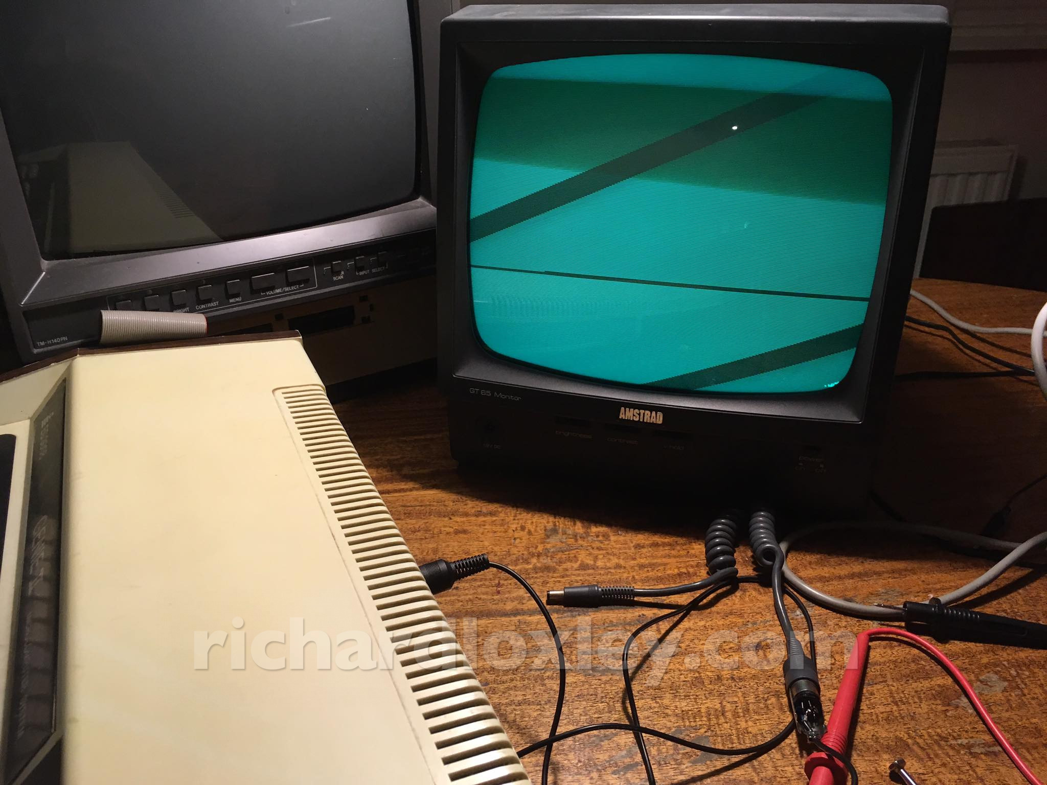
I was trying to get the Video Genie to work with an Amstrad green screen (GT65) monitor. I reckoned they’d be a good match (plus I’m not sure I can get my forthcoming frame buffer converter to work with the composite video signal from the Video Genie).
But after soldering up a phono to 6-pin DIN lead, the picture just rolls, as if it isn’t getting a sync signal.
Sure enough, the GT65 pin out doesn’t specify video, it specifies *luminance*, with a separate sync pin. It expects a pure luminance signal, with a composite sync delivered separately.
I tried putting the composite video signal onto the sync as well as the luminance, but it obviously isn’t clean enough as it didn’t work.
Now interestingly, the sync stripper circuit I’m planning to build for my framebuffer project, is designed to separate out the composite sync from a composite video signal, to feed into the frame buffer. But maybe I don’t need that to feed in the Amstrad signal if it already has separate composite sync?
But then maybe I instead need the sync stripper to go the other way and create a composite sync signal if I need to use the Video Genie with the Amstrad monitor!
Argh, plans! Much easier to follow when they don’t change!
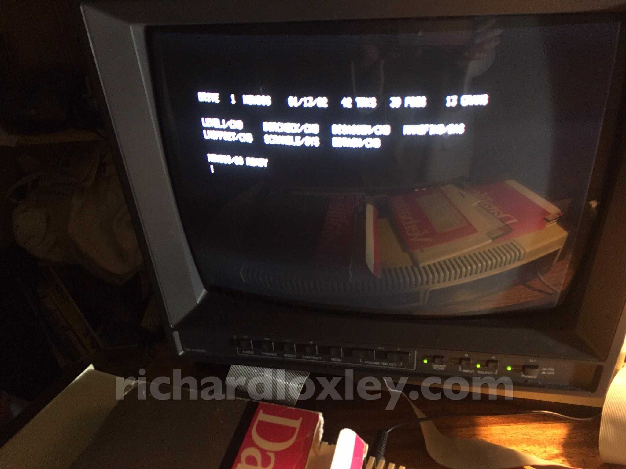
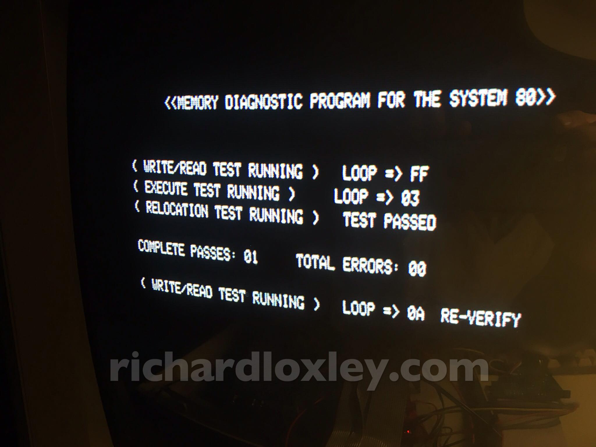
Next up, I found a system test disk for the System 80 (that’s what the Video Genie was called in most countries). It did a soak test of the RAM, and all looks good ![]()
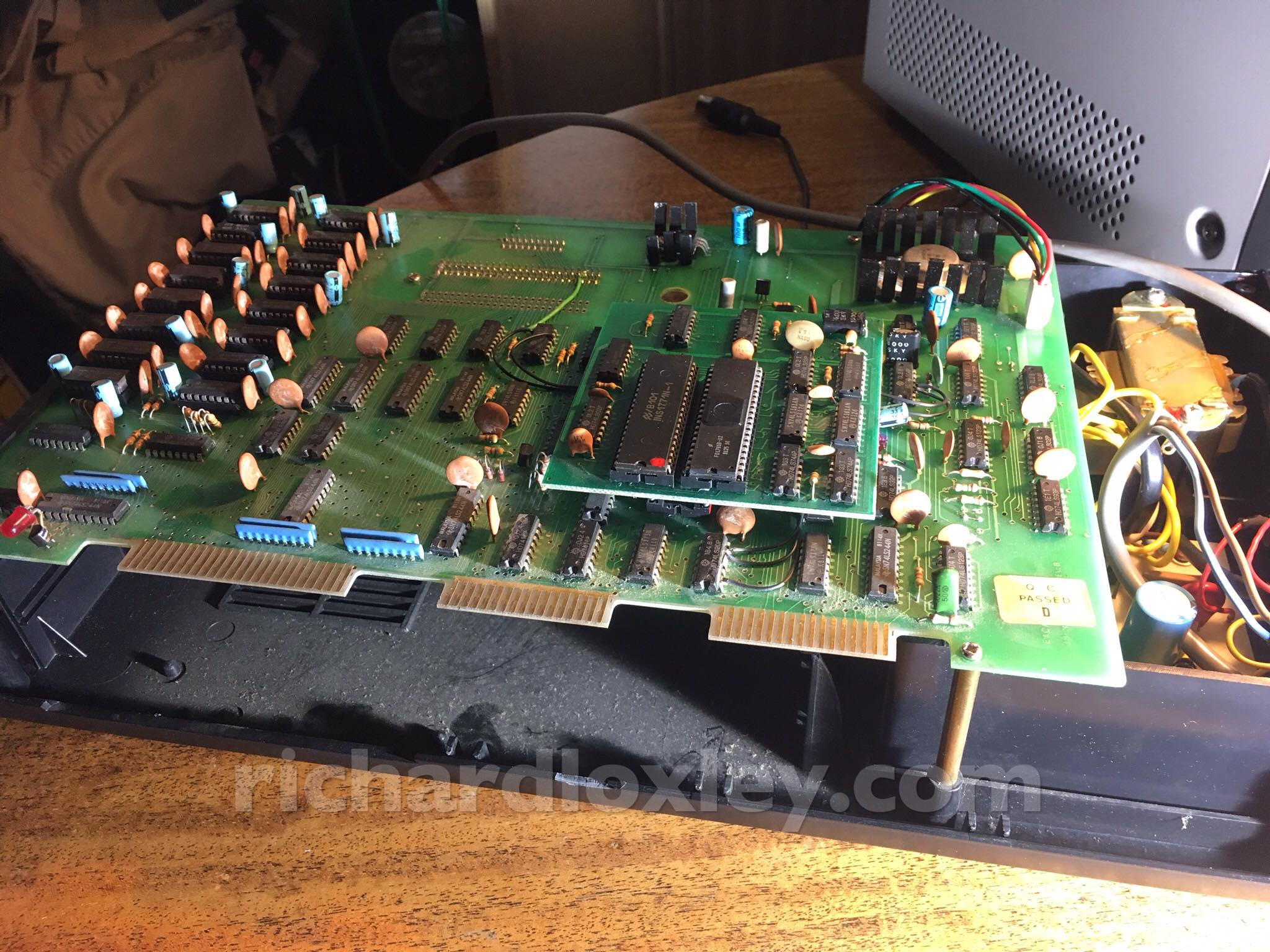
I decided to finally open up the Video Genie expansion unit to have a look. It’s the box that adds the disk interface and an extra 32KB of RAM, as well as having slots for an RS232 interface and an S100 expansion card (neither of those currently fitted):
I did this partially out of curiosity, and partly to follow the disk interface connectors to see if the lines for drives C and D are actually wired up. They seem to be, and that’s also what the manual says.
That’s good, as it potentially gives me the option to run a USB floppy emulator alongside the twin physical disks.
Here’s what the manual says about the disk interface wiring (which is consistent with the Shugart floppy standard):
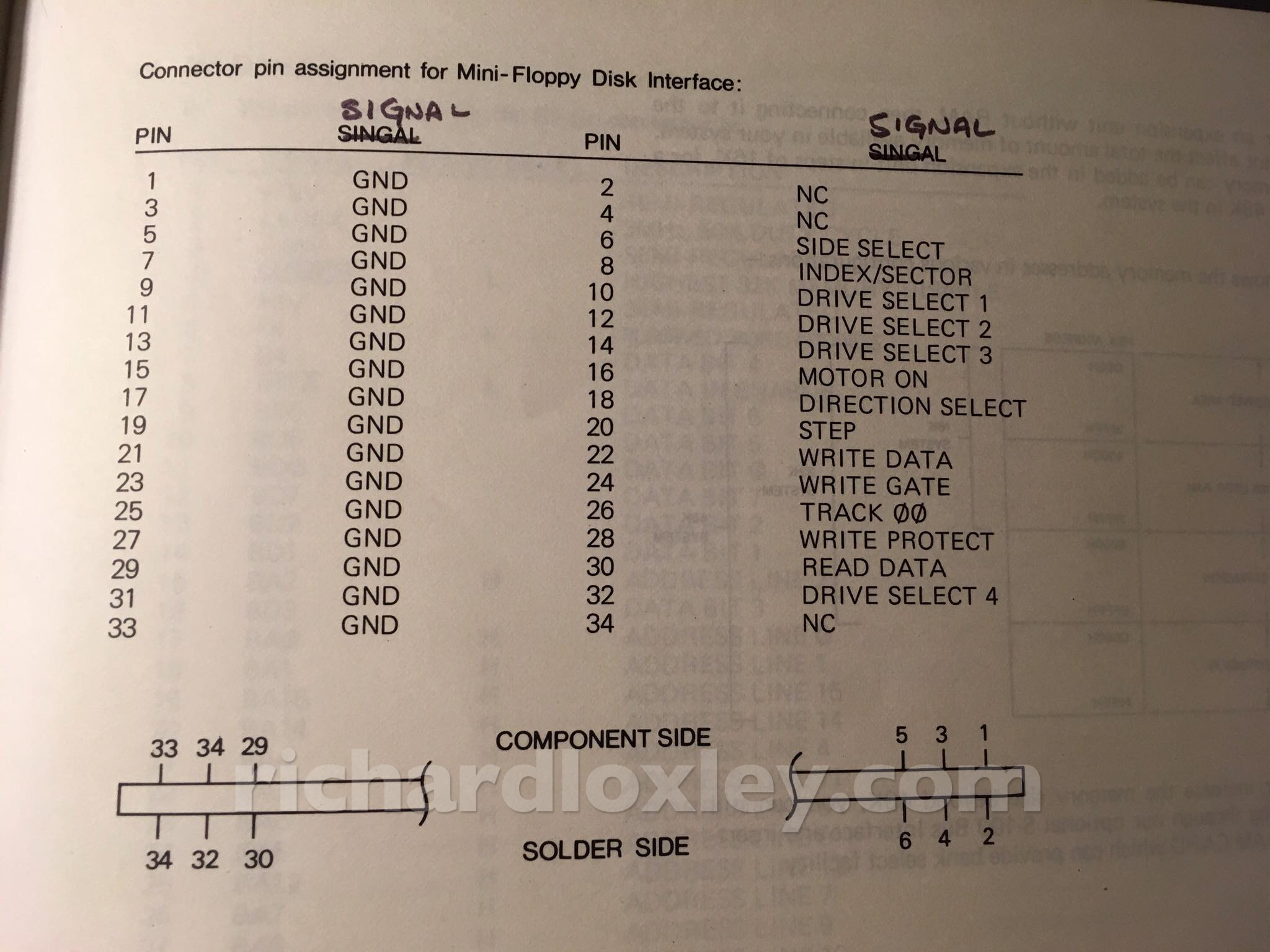
Of interest are pins 10,12,14, and 32, which select which of the four disks is being accessed.
Note that some places refer to disks 1-4, and others 0-3. To prevent ambiguity I try to use A,B,C,D ![]()
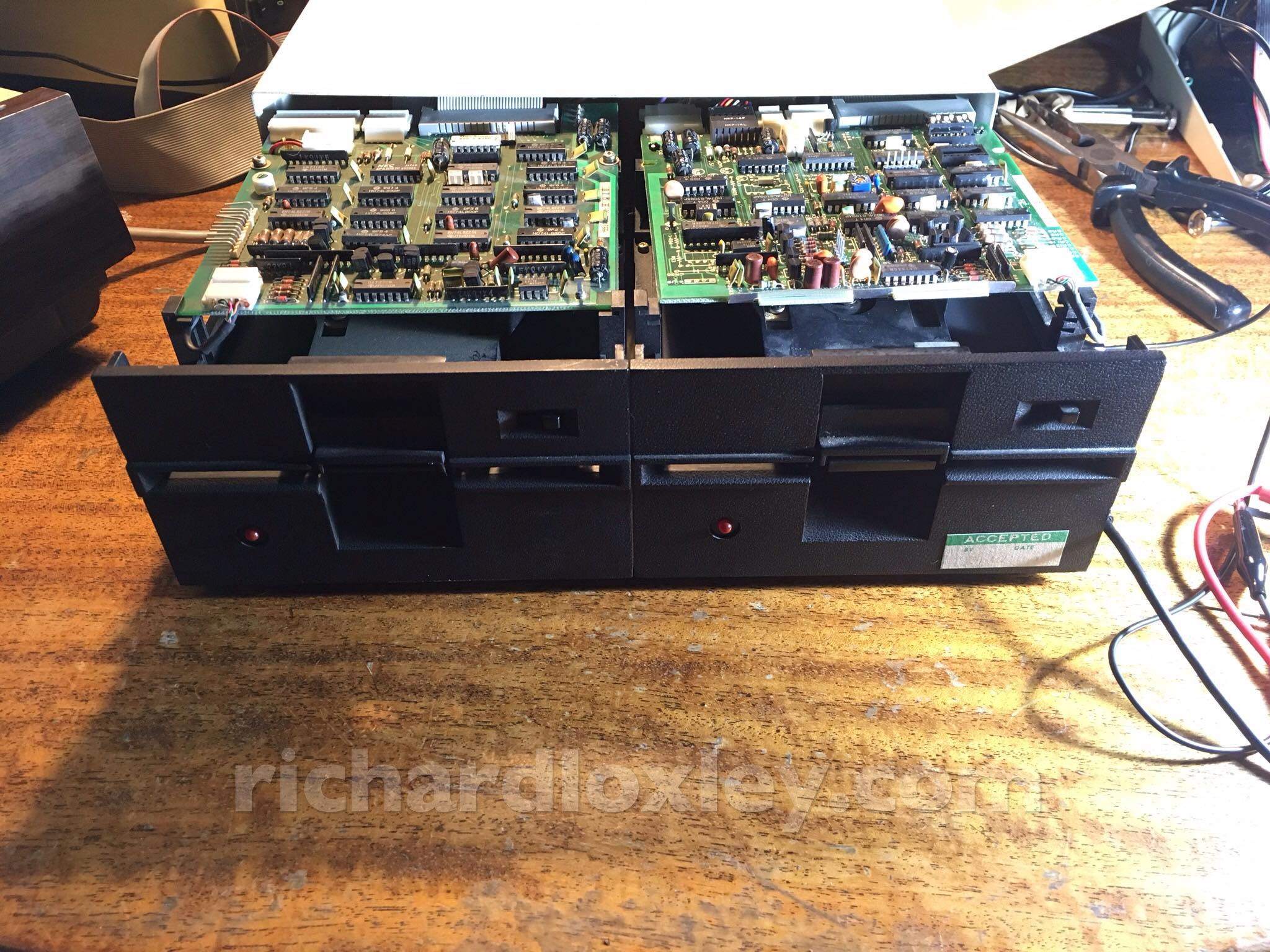
Next to open up the twin disk unit to see how that’s wired up, and see if I can fix the second drive (only one drive worked when it arrived, although both worked before it was shipped by courier):
Here’s the working drive (with cable removed). A jumper allows it to act as A, B or C. It’s currently A. The connector for D is there, but it’s not clear that it goes anywhere useful. The lack of a jumper suggests the drive cannot be D.

Here’s the connector for the non-working drive. It has DIP switches instead of jumpers. It appears to support being A, B, C, D with the switches 1,2,3,5 from the right.
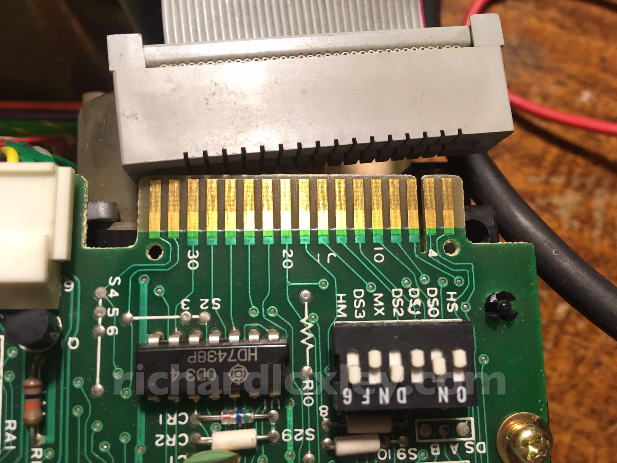
It looks like it’s trying to be drive B, but the switch isn’t fully on. Is that the problem? Did the switch get knocked in transit?
I tested the switches and traces with a multimeter. The switches for A and B connect the corresponding cable pin to the resistor R10. But the switches for C and D don’t do anything. The cable connector for D (remember its pin 32 on the far left) is connected but doesn’t seem to go anywhere near the DIP switch.
The DIP switch is socketed, so I remove it. The third pin is broken, which is why the drive C switch doesn’t work:
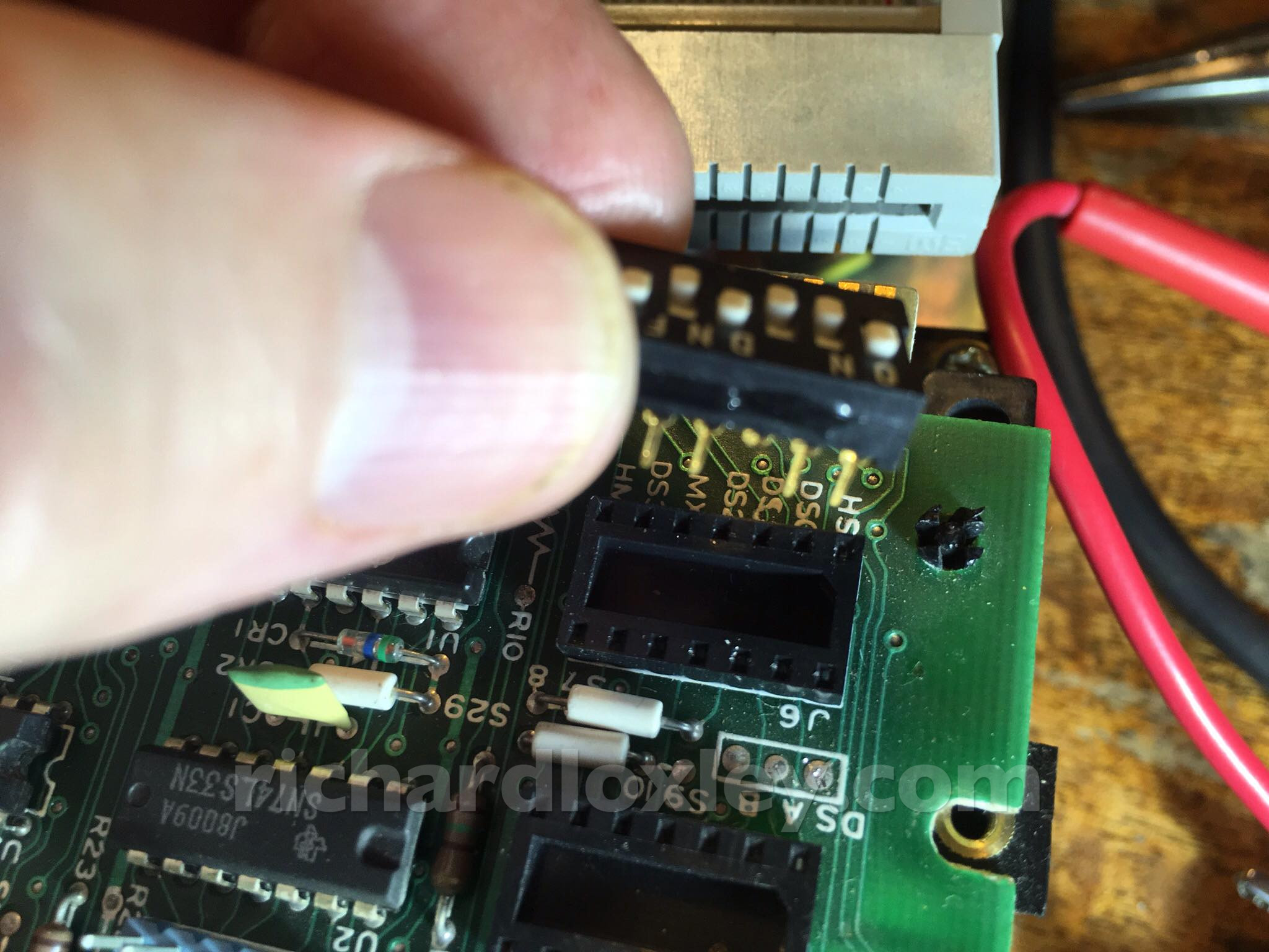
So it looks like each drive can theoretically be A,B or C, but they haven’t allowed for D. And this drive can’t be C because of the broken pin.
Still, between them they can be any two out of A, B, and C, which is fine ![]()
So I provided I can wire up an extra connection on the cable, I can add a USB disk, and have A, B and C drives.
I think it probably makes sense to leave the two physical disks as A and B, and put in a switch to allow my USB disk to be whatever I need.
That way I can run the Genie with just the USB disk as A, or I can use just the physical disks as A and B, or I can have all three with the USB as C.
That makes most sense, as the main reason for connecting all three is if I want to copy files between physical disks and USB. In that case I need a boot disk as well as the two disks I’m copying, and if the USB is one of the disks being copied, it can’t be the boot disk. (The boot disk is always drive A).
All this is input to the planning stage. I was basically trying to work out whether my USB disk should have a switch for A and B, or to allow C and D as well.
So A/B/C/D it is.
I reassemble the drives and test them.
And indeed the DIP switch in the faulty drive was the problem. Once I pushed the switch all the way closed and reassembled the drive, everything’s now working ok ![]()
I now have two fully working physical disk drives on the Video Genie. (Here’s drive 1 aka drive B working nicely again.)