I’m building what I call the “RetroMatic 2000” for the Retro Challenge 2017/04.
I’ve been planning, designing, and prototyping it for the last month or so.
Here’s a scrapbook of what I compiled during the research and development phase for the video converter aspect of the project (converting 288p RGB or mono composite from a retro computer to VGA suitable for an LCD monitor).
Thinking about how to connect the Amstrad (or any other retro computer or gaming console) to a VGA monitor.
I’ve done lots of research, and it needs quite a few components, but they’re all low cost.
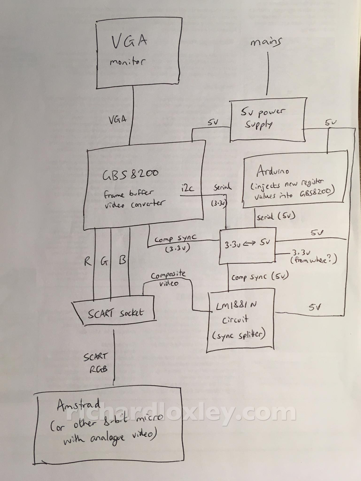
The main thing is a GBS8200 board, designed to digitally buffer an analogue video signal and convert it between formats. They are designed for arcade machines that need to be converted from CRT to flat screen monitors. They are only about £15.
Then SCART leads usually use the composite video signal to provide the sync signal. You can feed that into the GBS8200 but it expects a clean sync signal without the extra composite video signal so doesn’t give an ideal result. To fix that you use an LM1881 chip to filter out the sync signal from the video line.
But that chip outputs 5v, and the GBS8200 works on 3.3v, so you need to convert it.
Finally the GBS8200 can be configured by an onscreen display, but has limited options. It apparently doesn’t have many modes for 50Hz inputs, and often gets deinterlacing wrong. But the chip on the board supports almost any video mode. So the Arduino bypasses the controller chip and feeds parameters directly into the video chip. There’s been a lot of community work on getting that to work, which I’ve been reading up on!
Finally I’d need a 5v power supply for everything. I might also need a voltage regulator to get 3.3v into the level converter. Or there might be a 3.3v line I could hack on the GBS8200 to grab that?
Also wondering about building the HxC SD card floppy emulator into the same box and using the same power supply?
And maybe make the power supply big enough to power the Amstrad too, since it won’t be able to get its power from its monitor. If I wanted to run the 6128 disk drive I’d need 12v too, but probably not necessary as the HxC will eventually make the disk drive redundant.
If I built all that into one box, I’d then have a solution that would supply power, floppy drive emulation, and VGA video output, to any old computer. That could be quite cool
I’ve been doing more research on the Amstrad video format, and why modern TVs (and some converter boxes) don’t work with it.
In fact the issues are common on all 8-bit micros, and even some 90s video consoles (e.g. PlayStation 1 I think).
Issue 1 is that the SCART socket specification changed somewhere along the line (back when I made my SCART cable, my TV was almost unique in having a SCART socket). It seems that one of the pins is now used to switch the TV between composite and RGB video. So you need to put 3v onto that pin for the TV to look at the RGB pins. There are some solutions out there with batteries, and others trying to hijack some voltage out of the oscillating sync signal using a capacitor!
It might be worth me trying playing with that to see if my TV can be persuaded to accept the Amstrad RGB signal. Although I suspect that’s not the issue as the Amstrad also puts out a monochrome composite video signal, so I should have at least seen that. Plus it would be good to be able to use a computer monitor which doesn’t have SCART anyway.
Issue 2 is the way all 8-bit computers output video. Analogue TV signals were 625 lines (576 visible lines) in an interlaced format: the 288 odd lines sent first, then the 288 even lines. 8-bit computers just didn’t have the memory to handle 576 pixels vertically.
So to make things simple, they put out a progressive (non-interlaced) video signal, using a slight hack. They used 288 vertical pixels, and just displayed them twice. (In fact the Amstrad only stored 200 vertical pixels and filled the rest with a coloured border to save even more memory). This is now known as 288p (you’ll also see references to 240p in America, corresponding to 240 lines out of 480 visible in a 525 line signal).
The way they sent them was also a hack, as normally the second field of interlaced video has a delay of one scan line, to make it appear on the even lines. But this 288p signal sent the second field early, so the signal appeared once again on the odd lines.
Analogue sets just trigger the frame fly-back based on the sync signals, so don’t care about the slightly odd timing of the second field. They also don’t care that the even lines never get drawn (which lead to blank horizontal lines on the picture, emphasising the pixelated look of 8-bit graphics).
But modern sets digitise the analogue signal as it comes in, to display it on a digital display. Some circuits cope with the slightly odd timing, others reject it entirely.
Even those that accept the signal introduce another problem. Digital sets are progressive (non-interlaced) displays. So they use ‘clever’ algorithms to interpolate between the lines, and between the frames. This is a bit of an art, with some doing better than others (and which can introduce odd effects on horizontal motion).
But that’s even assuming they have a correctly interlaced signal fed in. When fed with a progressive signal, that has ‘blank’ lines on every other field, they try to interpolate between a picture, and nothing, every other field. That leads to very strange motion artefacts indeed!
The off-the-shelf “SCART to HDMI” adapters suffer from exactly the same problems, as they are expecting 576i, not 288p!
Apparently the beauty of the GBS8200 is the chip on it can be told to expect progressive 288p on the input, so it doesn’t de-interlace. And therefore puts out a nice clean progressive output on the VGA output :-) But it needs the extra hardware to put the input into progressive mode, and to tell it to output in 50Hz so it doesn’t try to convert the framerate to 60Hz.
One extra modification that many people make is a scanline generator. An original monitor would show gaps between each line (288 lines shown on a 576 line display). But a framebuffer conversion will double-up every line to make a clean 576 line image, arguably improving the display. But it won’t look like the original. So you can buy scanline generators that will put the lines back in on a VGA output!
These work by blanking out every other line on the VGA signal. So that will be fine if you output a 576 line signal on VGA, and if the monitor accepts it. But if you choose a more standard resolution, it will put the lines in at the wrong points. (It probably works better with NTSC devices as they are 240p displays on a 480 visible line signal out of 525 total lines. So a 640×480 standard VGA format works well.) Having said that, I’ve seen reports of people using 576 lines on VGA monitors ok.
I think a scanline generator is a future enhancement I might look at if I’m not happy with the results. Bought ones cost €40 in Europe, or $15 in the US (but horrible postage costs). But I’ve found a 2-chip design to make one yourself for very little.
What fun ![]()
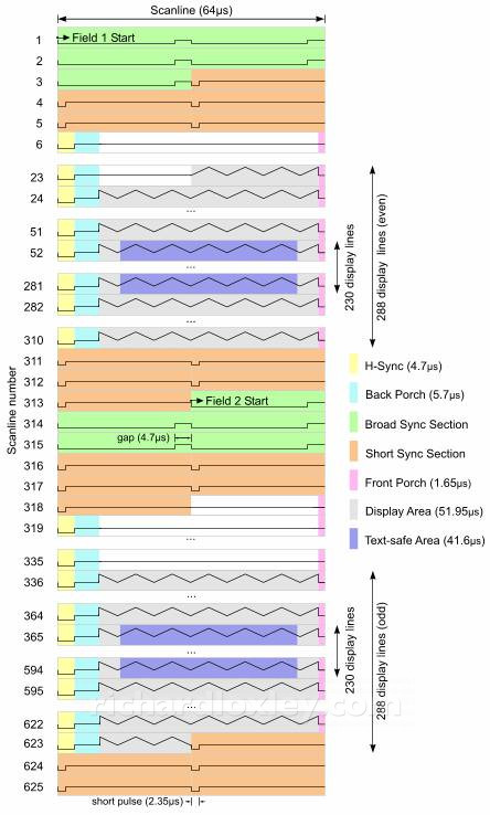
I found this superb illustration of (monochrome) 625/50 video signal timings that shows how two interlaced fields are transmitted.
Image from http://www.batsocks.co.uk/readme/video_timing.htm but reproduced here in case that link disappears.
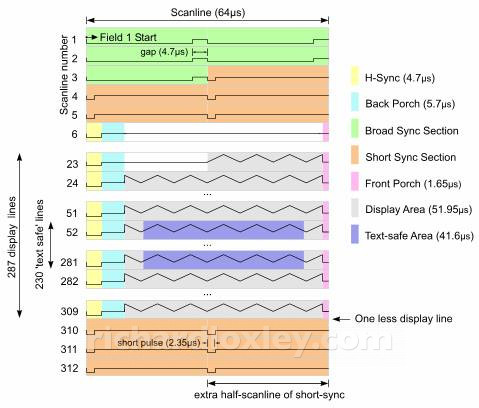
And this shows how the 8-bit machines faked a half-resolution progressive signal into a single (repeated) field. The actual page is talking about making your own simple video output in the same fashion.
Image from http://www.batsocks.co.uk/readme/video_timing.htm but reproduced here in case that link disappears.
I’m also thinking about how to get my new Video Genie talking to a VGA monitor. The GBS8200 board combo I’m buying/making will take 288p RGB and converts to VGA. But the Video Genie puts out (monochrome) composite video.
All the stuff out there talks about how the GBS8200 can’t take composite video. But they are presumably talking about true composite video, i.e. a luminance video signal with a chroma (colour) signal embedded on a sub-carrier. The Video Genie won’t have the chroma signal.
The GBS8200 can take either RGB or YPbPr. My understanding of YPbPr is Y is pure luminance, with Pb and Pr being the difference between the luminance and the Blue and Red signals (then Green is whatever is left over). So I’m thinking I can just feed a monochrome video signal into the Y channel and it should convert it? Although perhaps it will come out in green if the Pb and Pr are both held to ground?
Or maybe I can feed the monochrome signal into all 3 of R G and B? The problem is the video signal has sync signals embedded in them, and the GBS8200 expects the sync to be separate to the RGB (which I can also feed in separately). I wonder if it will happily ignore the extra sync signals?
I think some experiments are needed!
Update: I found this on an AV forum (in conjunction with an obscure Karaoke machine with only composite output:
You don’t need a converter if black-and-white (greyscale) is adequate for you.
Plug the composite cable coming from the receiver into the component video’s Y connector on the TV. You’ll get at least a black-and-white (greyscale) image
So maybe my theory is correct.
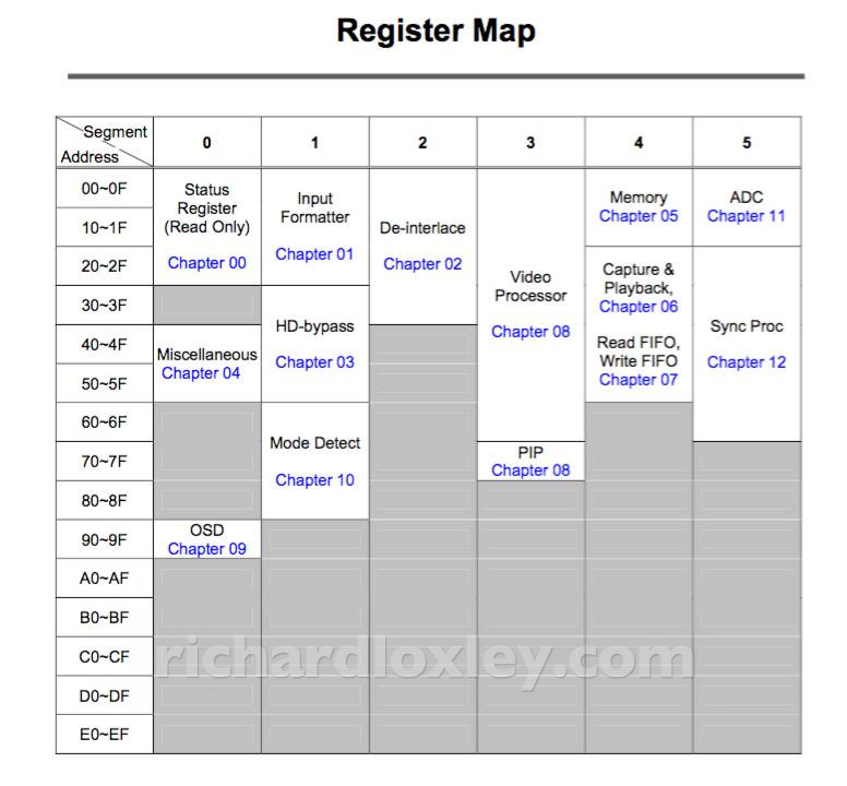
Limited time today to work on projects, but I’ve been delving into the firmware manual for the TV5725, which is the video conversion chip on the GBS8200 framebuffer board I’m going to get.
It’s a very dry manual, just listing all the registers that control the conversion, with a brief description of what each does (but no explanation or examples of why you’d want to change it, or what you’d set it to.)
But I have a plan…
Several people have been hacking with the GBS8200, using either Raspberry Pis or Arduinos to inject values into the TV5725 chip via a serial link: dooklink, mybook4, pulkomandy, bhabbott, kernelcrash.
Their code has blocks of data to write into the registers for different use cases. I’ve been pasting these blocks into a spreadsheet, tagging them with the register number, and using conditional formatting to easily identify values that are different (out of 1500+ register positions).
I can then look up the values they’ve changed in the firmware manual to see what they do.
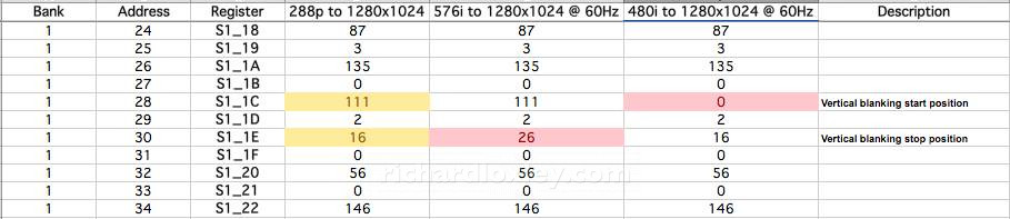
For example, this is one register that is different between 50Hz and 60Hz output. Why needs more research of course!
My ultimate aim is to tweak the output further than others have done.
Most people working on this stuff are in the US, so are converting a 480 line TV picture into 640×480 pixel VGA output, which works nicely.
But I’m dealing with a 576 line UK TV signal, which doesn’t go nicely into VGA resolutions without potentially having scaling artefacts. And if I want to do a scanline generator to authentically show 288p, I need to have an exact multiple scaling factor of the lines.
What I’m hoping I might be able to do, is perhaps scale a 576 line display into 800×600 with a border around it. I don’t yet know if that’s possible with this chip, but let’s see ![]()
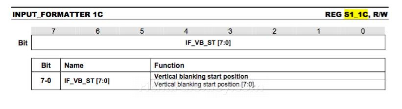
And see what I mean about the manual? This register is “IF_VB_ST”. Which stands for “Input Formatter Vertical Blanking Start position”. And the explanation of that is merely “vertical blanking start position”.
I do vaguely know what the vertical blanking start position is. But what units is it in? Scan lines? Timing offset within the signal?
This manual is really designed as an aide-mémoire for someone who already knows all this stuff.