After my testing of the HD9800 video converter board, I wanted to experiment with reprogramming the TV5725 video conversion chip on the board.
A number of people have already done sterling work on reverse engineering it to invoke modes not supported by the supplied on-screen controller: dooklink, mybook4, pulkomandy, bhabbott, kernelcrash.
I hope to build on their work :-)
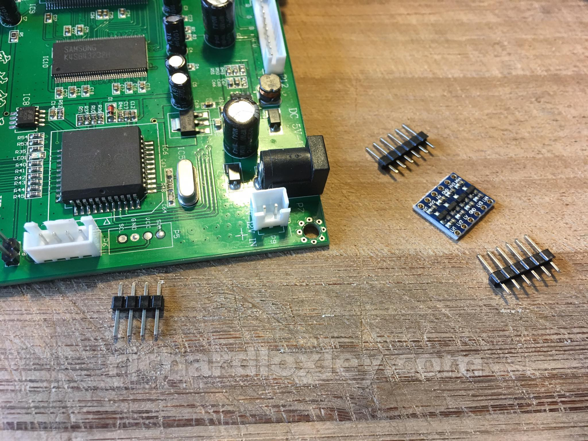
First soldering job of the day: attach the header pins to the 5v-3.3v level conversion board, and attach header pins to the i2c serial port on the HD9800.
The latter could be a bitch, as the holes are already filled with solder. So I either have to do all 4 pins at once (not very likely) or remove enough solder first that I can push all 4 pins through.
So the header pins got soldered, but in the solder removal I damaged two PCB tracks ![]()
The dodgy ones were VCC and SDA. I’ve tested VCC with a multimeter and it works. Won’t know about SDA until I try out the i2c serial link and see if any things comes across.
Hope I haven’t knackered it. It would probably mean a new board as I’m not sure I have the skill to repair it.
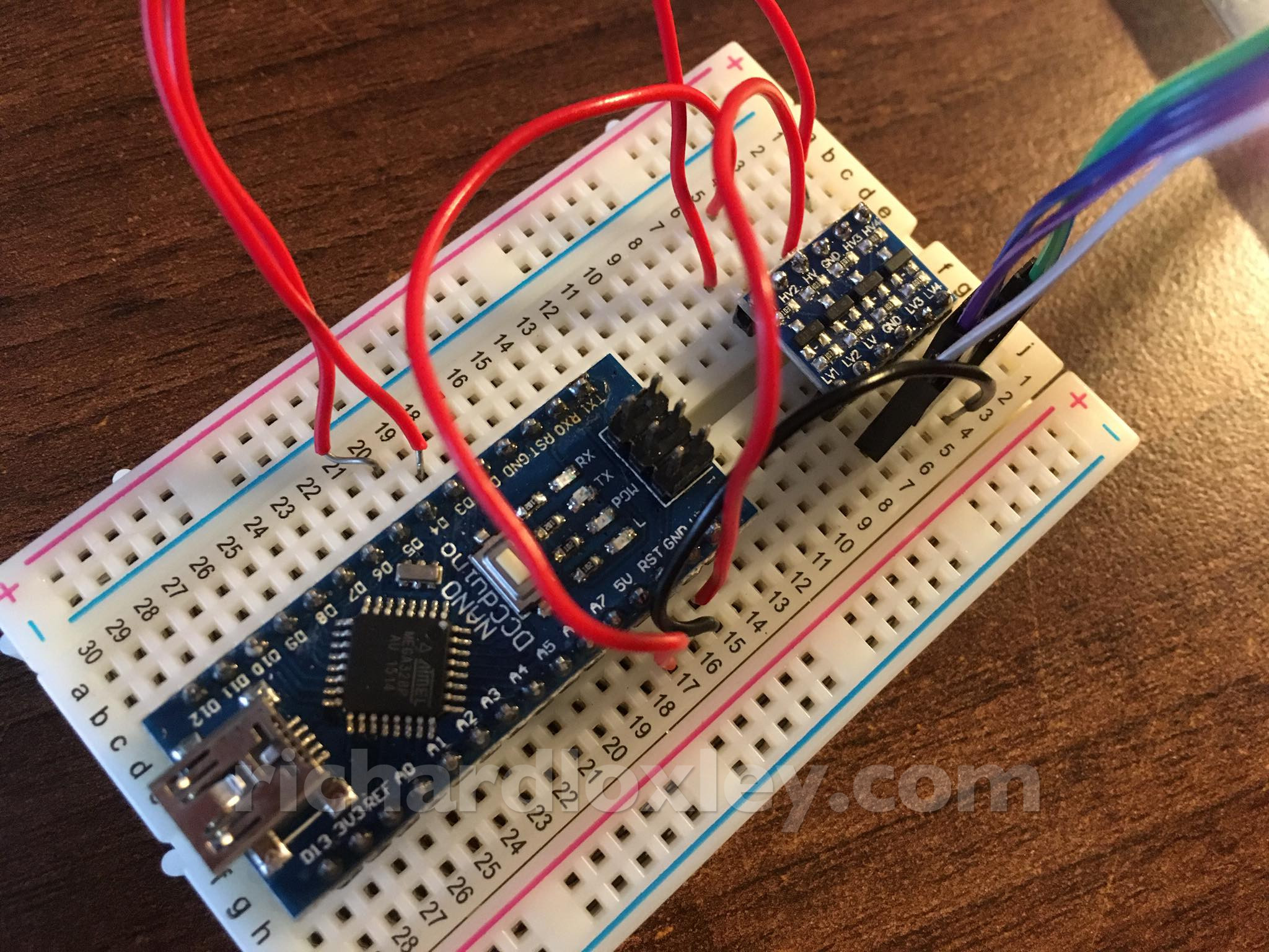
I connected up the Arduino to the i2c header via my newly soldered up level shifter board. I’ve download some example software, but now I need to add some debugging so I can tell if the i2c is actually working.
The last hour has provided despair, disillusionment, methodical progress, and now hope.
The i2c header pins I soldered on are P5 (top right). I’d connected them to the Arduino, wrote some code to read some registers, debugged an Arduino IDE issue to write the code to the Arduino, and tested it.
Each register I read was successful, but gave me a value of 255 – not right.
I tested the voltages going through my 5v-3v level shifter. 3v on the 5v side, 1.5v on the 3.3v side. Not right. Discovered the Arduino wasn’t fully seated on the breadboard (new breadboards that are very stiff). Pushed it home.
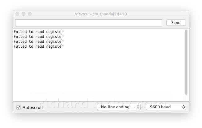
Now the code says it fails to read registers ![]() I think the i2c header I soldered on is buggered.
I think the i2c header I soldered on is buggered.
(Aside, auto correct changed buggered to buffered. Quite a clever substitution for a serial link, but incorrect in this case!)
The SDA pad on the header was damaged as I initially desoldered it. I thought there might be enough left to work, but apparently not.
Next step, trace the SDA line and see if there’s anywhere else I can connect in.
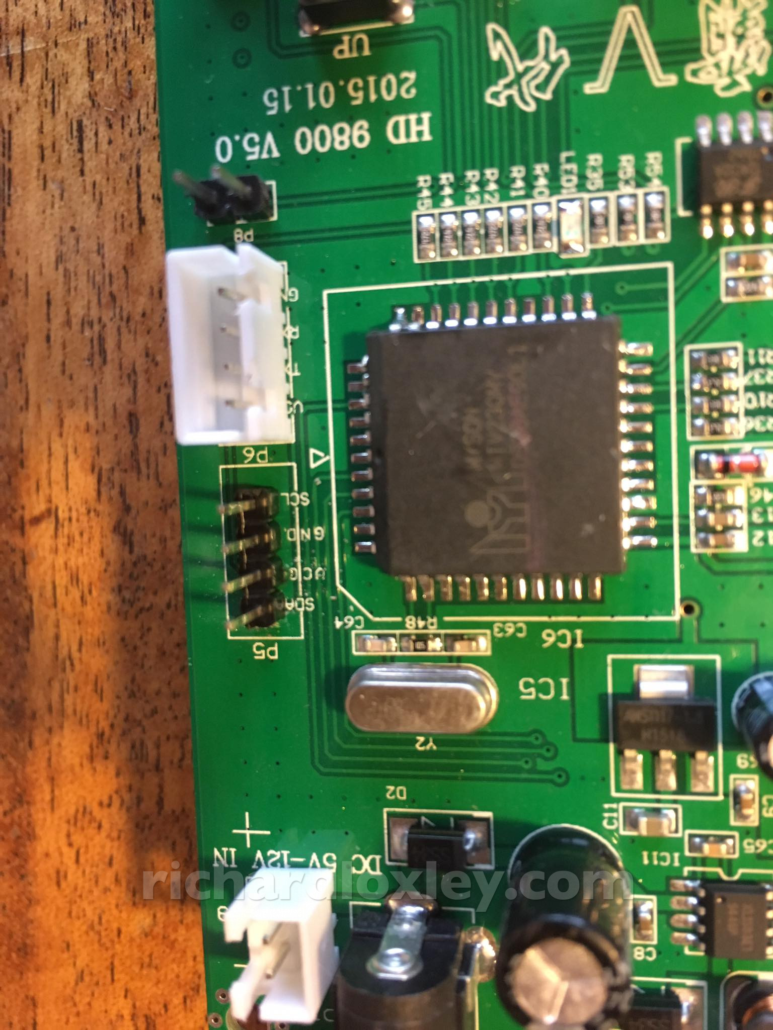
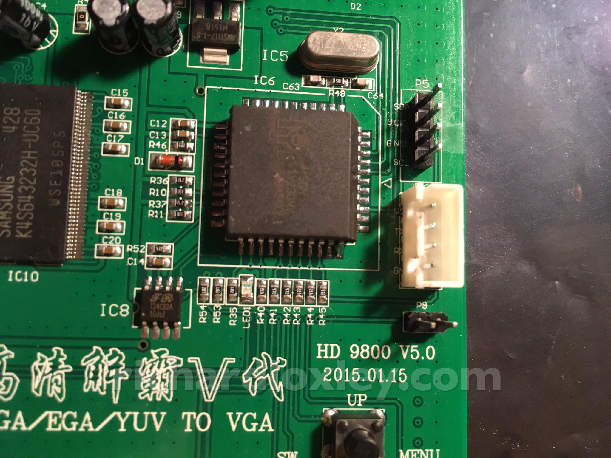
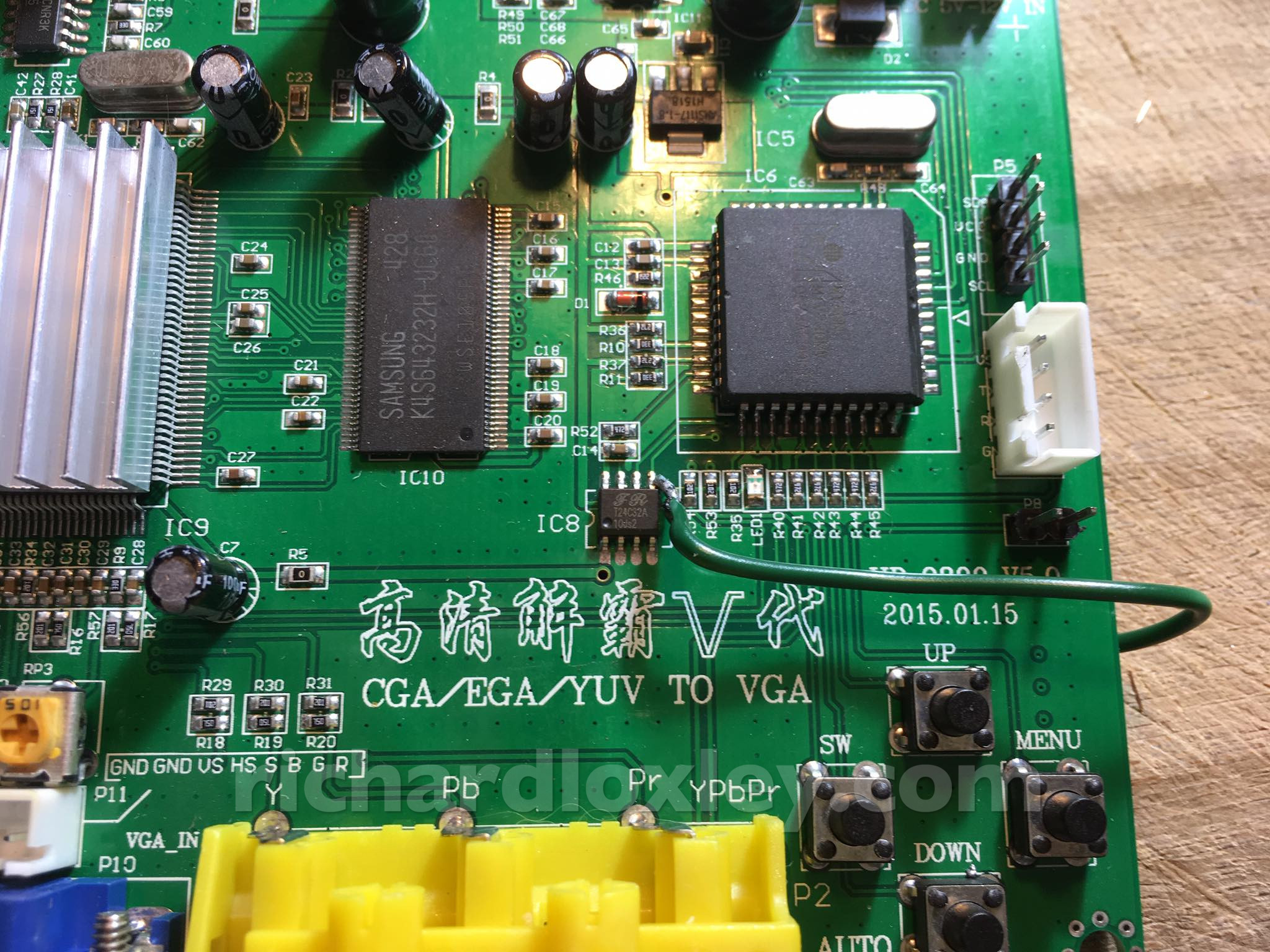
Quite hard to do, but I managed it! Both SDA and SCL pop up again on the two top right pins of IC8 (bottom left of picture).
What is that IC? It’s a T24C32A. Google tells me it’s an EEPROM. What? The serial link goes to an EEPROM, not the video chip?
The data sheet tells me it’s an EEPROM where you can set and read individual bytes via i2c! The programming manual for the TV5725 (the video chip) just gets you to set register values to program it. It seems you actually set the register values in an external EEPROM that the video chip also reads ![]()
(Update: I later realised that both the TV5725 and T24C32A are on the same i2c bus, so the P5 header can address any device on the bus. So the registers are probably being set on the TV5725 after all.)
So I look up the pin out for the EEPROM and put a multimeter on the relevant pins. The SCL pin is indeed connected to SCL on the header I’ve just soldered. Bingo! Got it!
But the SDA pin is not connected. So I did destroy the pad ![]()
Still, this gives me a second chance to connect into SDA. It’s a surface mount IC, so not great for soldering, but the pin I need is the corner one, so the most accessible one ![]()
So next plan: try very carefully to solder a wire onto that corner, and patch the other end to the underside of the P5 header!
But if I get this wrong the board will probably be a (very small) doorstop.
I’m about to do the most critical (and possibly hardest) solder joint of the project – repairing a damaged PCB trace by soldering a patch cable onto a surface mounted IC.
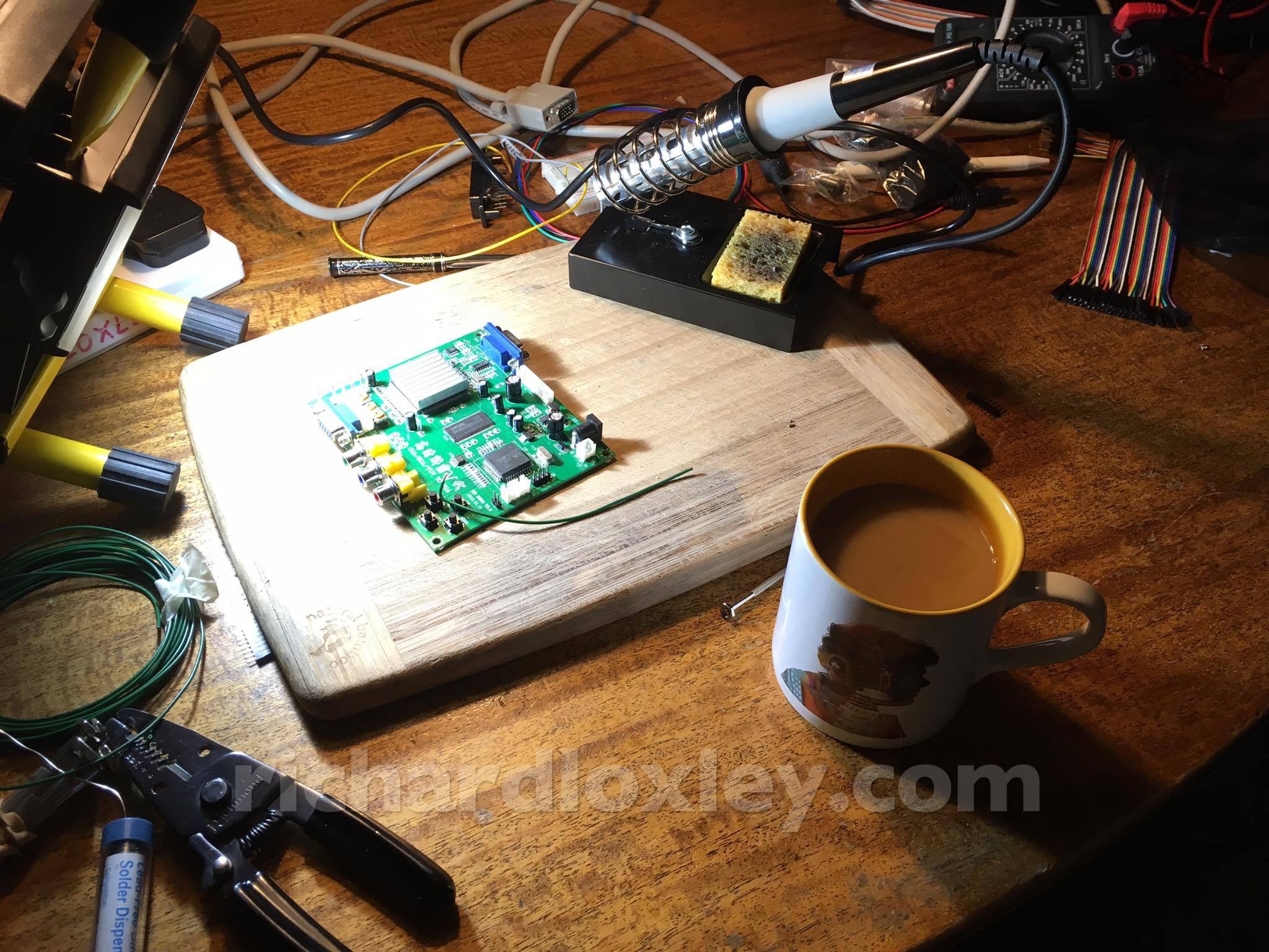
So I’ve got a super bright LED lamp to help my poor eyesight, and a cup of tea because I’m British ![]()
And done. Patch cable from the underside of the SDA header to the corner pin of the EEPROM:
And I didn’t even get half way through my cup of tea whilst doing it ![]()
Now to plug it in and see if it works:
Nope, the Arduino still isn’t communicating with the chip.
I’ve tested the SDA and SCL header pins are connected through to the IC using a multimeter.
And I’ve retested the whole board with the Amstrad and the VGA monitor to make sure I haven’t bricked it through static shock or thermal stress.
All looks good. So the presumption now is that there’s a fault with my cabling through to the Arduino, or in the software.
More debugging required.
So far in debugging:
Found I’d got the VCC and ground reversed coming from the i2c – oops.
Found I’d got SDA and SCL reversed too!
Still no joy, so found some generic i2c Arduino code. That suggested used a standard i2c library, which worked on pins A4 and A5 (but supposedly pins D4 and D5 on the Nano, but people were sceptical that that was correct).
Tried the standard library on D4 and D5, no joy.
Tried the standard library on A4 and A5, no joy.
Got out the multimeter to test the voltages on the pins. Only 2v on the 5v DC pin – what?
The Arduino now isn’t on, so the 2v is coming from the 3.3v on the i2c.
I occasionally get USB ports on my Mac dropping out for Arduino use for no explicable reason (until a reboot), so I try each USB port in turn – nothing.
I try powering the Arduino from a USB charger – nothing.
I think my Arduino might now be dead. Unless I’m missing something obvious.
Good news – the Arduino isn’t completely dead. It just seems that for some reason it will no longer take power from the USB port. If I power it from the HD9800 it powers on (and is visible via USB from my Mac – so the USB port isn’t completely broken).
I’ve also found some forum posts about talking to the HD9800 via i2c. One person did it via Raspberry Pi, one person via Digispark (a bit like Arduino) and then someone initially failed via Arduino, and was asking advice from the Digispark guy. The Arduino guy eventually got it to work, so I need to follow through his posts and try to get mine to do the same.
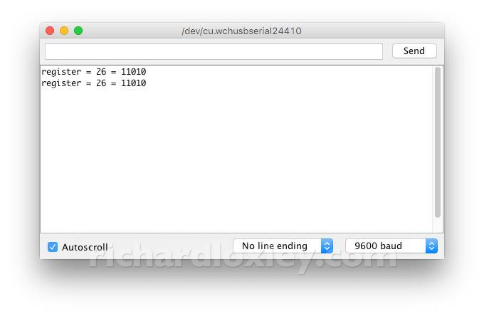
Woohoo! I’m getting values from the EEPROM connected to the TV5725 video chip via ic2!
This is supposedly the “Product ID” of the video chip.
I’m not sure what I’ve changed, but I unplugged all the connections, and re-connected everything methodically. I also deduced from scratch the IO pins on the Arduino that the software library used, and connected to them. (It turned out they were the ones I tried right at the beginning, but I may have had the serial pins reversed at that point).
I wrote code to dump all the status registers of the TV5725 video chip. Most just described the format of the video input (and I’ve got nothing connected):
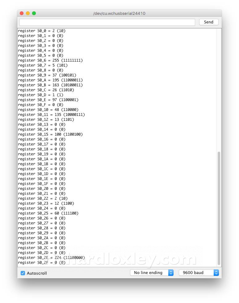
S0_0B to S0_0D describe the chip model (Foundry ID, Product ID, Revision ID). The values look plausible.
Now to connect a video input, see if the status registers change, and start writing values to the other registers (there are 1500 odd!) and see if I can change the video format.
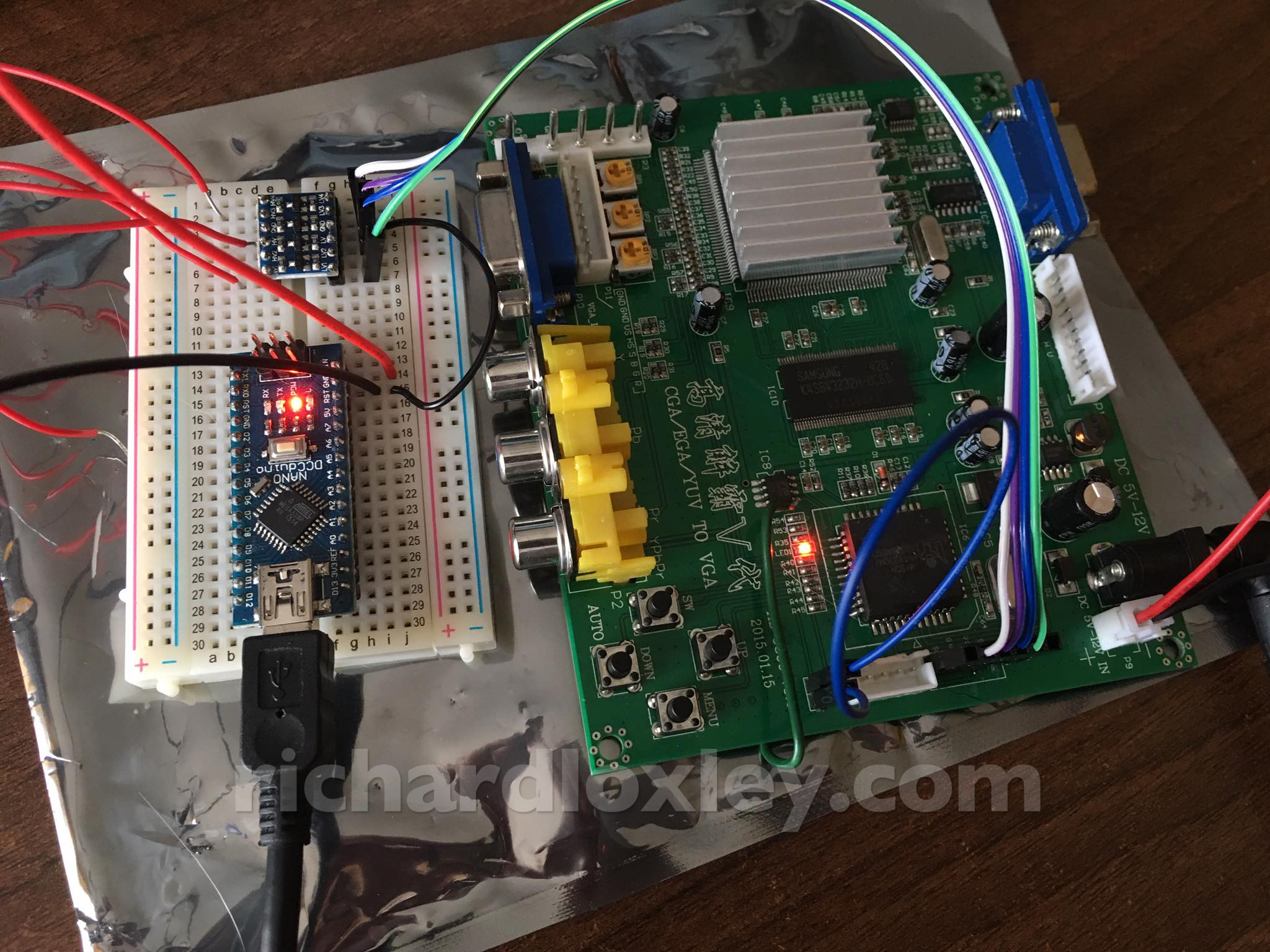
I’ve set up a little test bed in the corner of the office so I can start to play around with different video settings whilst having the USB link in reach of my Mac for reprogramming the Arduino!
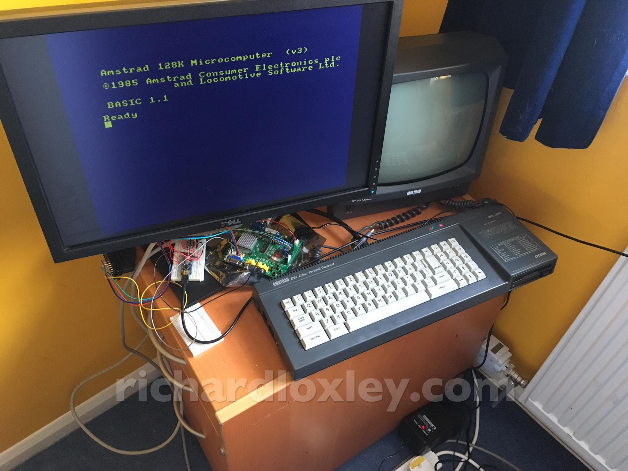
Pity I still need the green screen monitor there (the 5v power supply for the Amstrad comes from there, and all my universal power supplies jump from 4.5v straight to 6v).
I’ve got the Arduino reading and writing registers on the TV5725 video chip on the HD8900 board.
Here I’ve got a standard set of registers worked out by another enthusiast that will take 288p and give 576p without deinterlacing. Pretty much what I want:
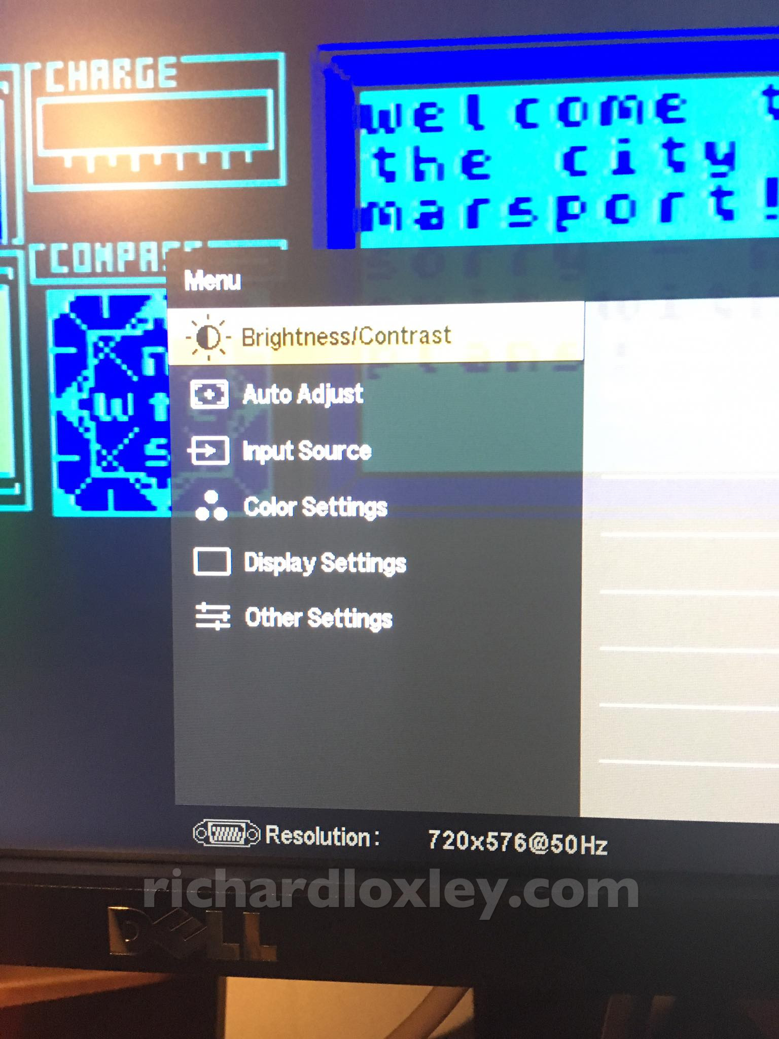
Of course 576p isn’t a standard VGA resolution, but both my Dell 24″ LCD and my Samsung 24″ LCD accept it fine. So perhaps I’ll stick with that.
There are still scaling artefacts as the Dell monitor is 1680×1050 native. The Amstrad only puts out 200 lines of the 288p. So if I could do a 4x scaling, with the excess (non drawing) lines clipped off the edge with the 800 visible lines in a 1050 display, that might be good? I need to play around with what’s possible.
Observant viewers will recognise what I’ve got loaded on the Amstrad. I picked it as it has a continuously sideways scrolling demo mode that with show up deinterlacing artefacts ![]()
So I’ve now got my Arduino reading and writing values to the video chip. Currently it writes a standard ‘package’ of values that another enthusiast has worked out.
Here I’ve written a text interface on the Arduino serial port to allow me to also read and write individual registers. Really clunky, but avoids having to recompile software and re-flash the Arduino for every experiment!
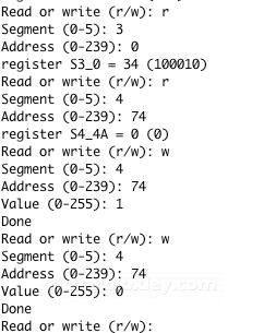
I’ve not yet had much success in changing stuff that has an effect, but early days! The chip supposedly has a crude On Screen Display (OSD), but I haven’t yet got it to work.
I’ve previously downloaded and read the TV5725 register manual (a very dry reference manual).
I’ve now managed to find a programming manual, which is laid out more as a tutorial of how to achieve different tasks by modifying the registers:
I’ve skimmed it all, and read some chapters in more detail. It still pre-supposes a great deal of knowledge I don’t yet have. But I guess that’s what happens when you read something marked “For Internal Use Only” ![]()
Still, the example for setting up the OSD didn’t work for me ![]() Needs more work.
Needs more work.