In my last three posts (update 1, update 2, update 3) I prototyped getting an HD9800 video conversion board to accept signals from my old computers and display them reasonably satisfactorily on an LCD VGA monitor.
But there is one major difference between the original video and the VGA signal: scanlines.
The early computers didn’t have enough resources for high-resolution displays. (The TRS-80/Video Genie had 192 pixels vertically, the Amstrad CPC series had 200 pixels vertically.)
A PAL TV signal had 625 lines vertically (576 are visible, the rest are ‘wasted’ as the electron beam moves back to the top of the screen). NTSC TVs had 525 lines vertically (with 480 visible).
So the computers used a trick to (mostly) fill the screen with their low-resolution signal: just put pixels on every other line of the TV. This is particularly effective because the TV signals were interlaced: first all the odd lines were broadcast, then all the even lines were broadcast to fill in the gaps. This standard signal is now known as 576i (576 visible lines interlaced) or 480i (480 visible lines interlaced).
The old computers instead put out a ‘fake’ signal: 288 lines (in PAL land) or 240 lines (in NTSC land), which just repeated for both odd and even fields of the video signal. They fiddled the timing of every other field so the lines were always drawn on top of one another, rather than in odd/even positions. We now call this 288p or 240p (“p” for progressive, or non-interlaced).
CRT monitors coped fine with this (they are just analogue circuits waiting for the next sync timing pulse). [My previous posts were about how to convert this signal to a form that modern digital monitors can cope with as they are expecting more accurate timings.]
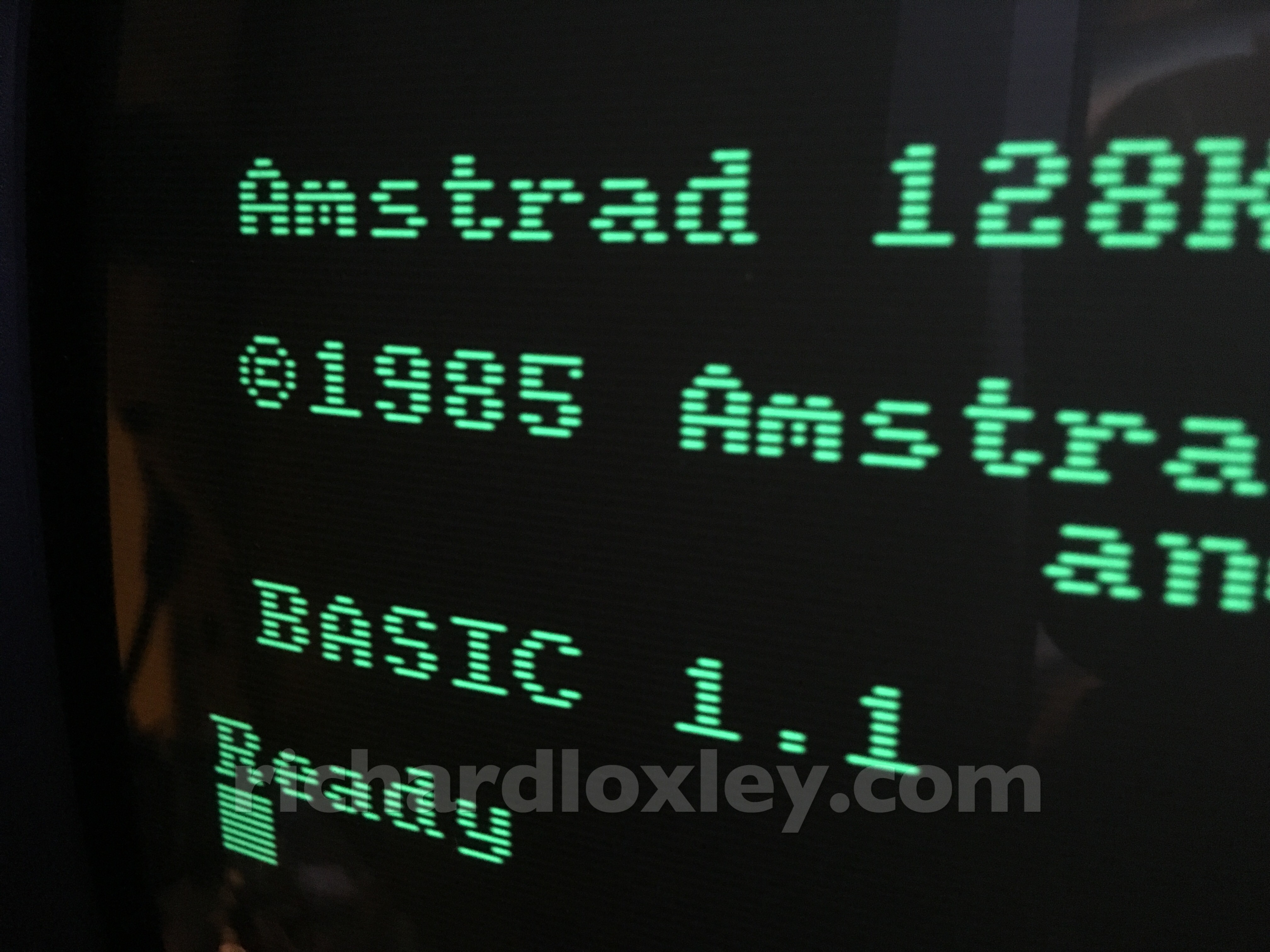
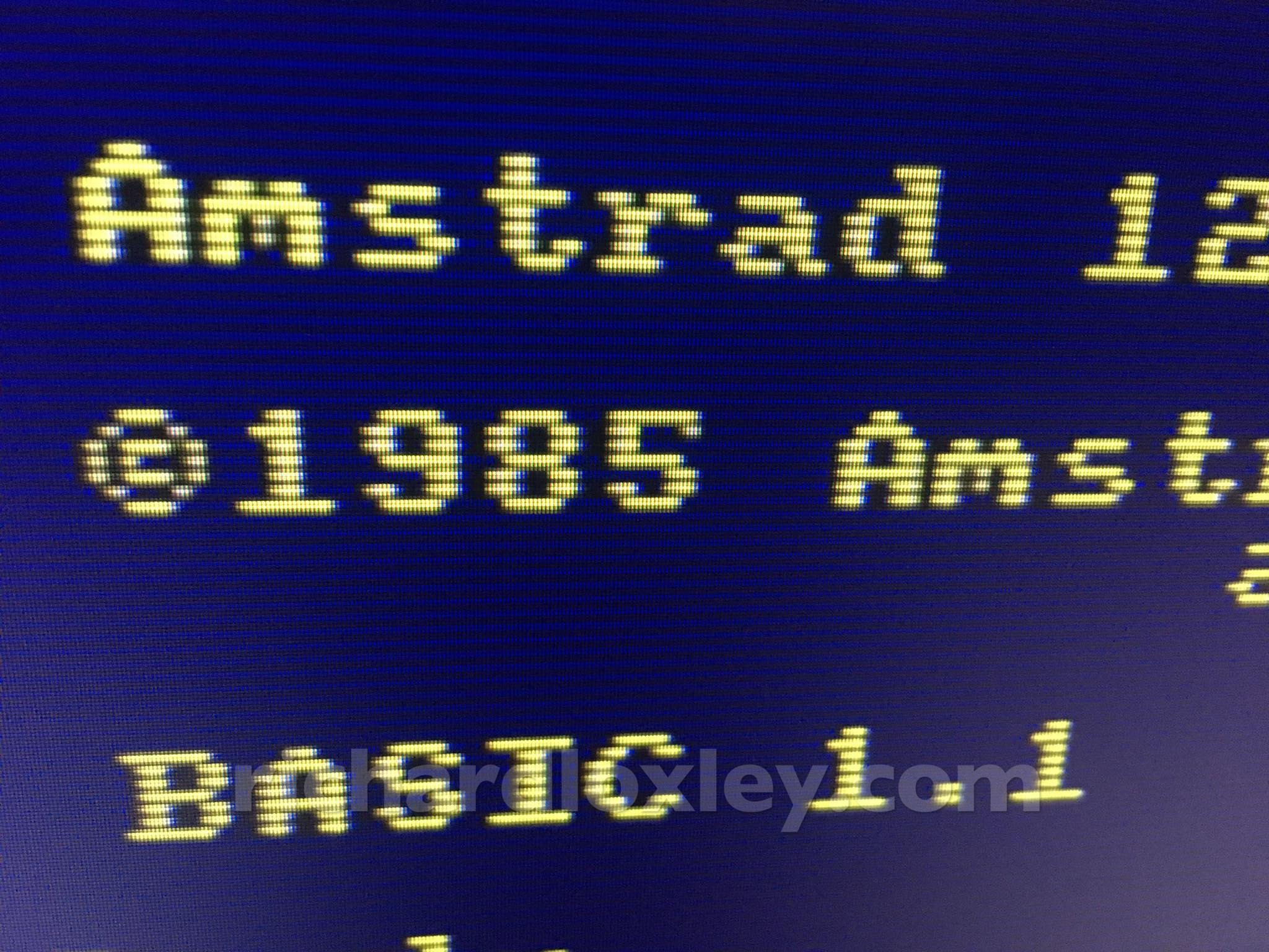
But a side effect of only drawing half the horizontal scanlines on the screen, was that every other scanline on the screen was blank, leading to a stripy pixelated look so evocative of machines of that era.
For example, here’s my Amstrad on its original green-screen monitor:
Now my experiments with the HD9800 conversion board will cope with 288p properly, but it correctly sees the signal as a whole video signal with just 288 lines, not a 576 line signal with gaps. In a way, this is what was intended by the makers of the computers, it’s just that interlaced monitors couldn’t actually display 288p “properly”.
So here’s the same output on an LCD VGA monitor via the HD9800:

Now in a way, that’s much better. It’s actually displaying 288p properly. But from a nostalgic point of view, it’s not displaying the way an original monitor would have displayed it.
For completeness, it would be nice to add back in the blank scanlines, so we can have a faithful reproduction of the video signal.
I haven’t found any way to get the TV5725 chip on the HD9800 to do this. However a number of people have found ways to re-insert blank scanlines into the VGA output after the processing by the HD9800. I’m intending to build one of these.
They mainly work by just blanking out every other line of the VGA output. This works fine if the resolution of the VGA output is twice that of the input, but if not, the blank lines will be in the wrong places, and won’t align with the pixels output by the computer.
In the NTSC world, this is mostly fine, as they used 480 line displays, and can use the 640×480 VGA mode. In PAL land we use 576 lines. Thankfully both my monitors can accept 576 line VGA input, although it’s not a recognised standard. That’s what I’m using for now, but I’m going to see if I can program the TV5725 to do other forms of scaling that will scale up the picture to a standard VGA resolution with an exact multiple of the input lines. We’ll see!
Anyway, to the scanline generator, which will insert these blank lines.
The design I’m using was invented by sharksym (although the instructions are in Korean). However mmmonkey has written up a nice English tutorial using the same circuit, which is what I’m following.
It uses two simple chips, a flip-flop to count odd/even lines, and a buffer/line driver to ground the video lines at the appropriate points to make them blank.
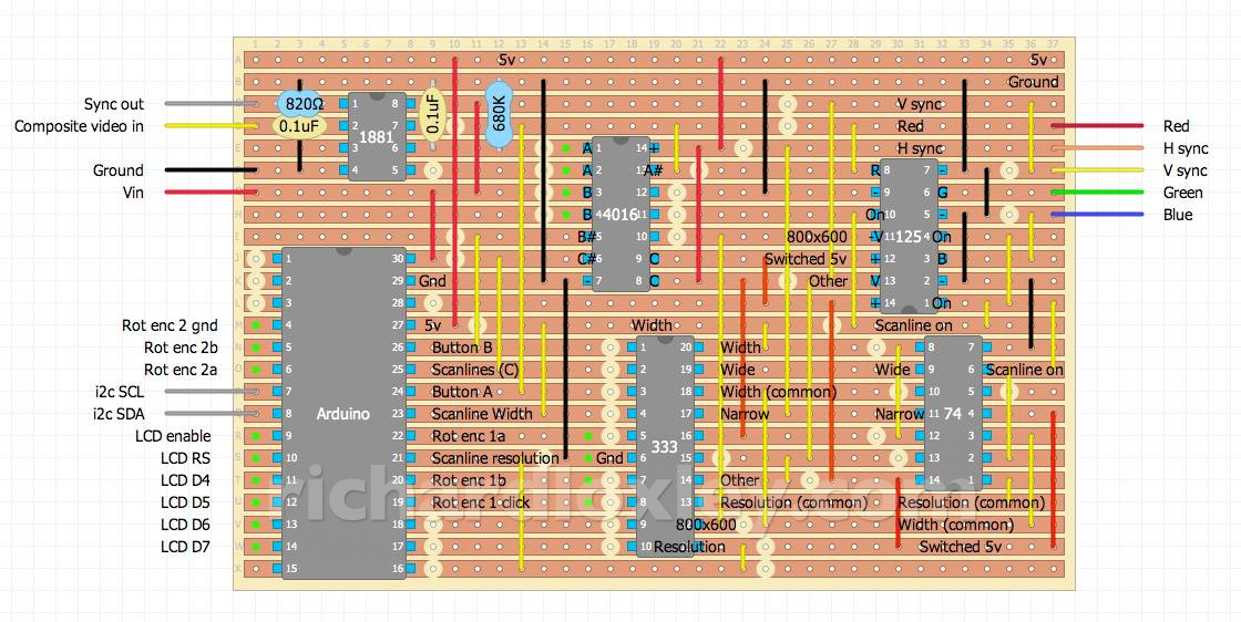
This is the circuit (this is mmmonkey’s diagram that I’ve annotated with the pin numbers for convenience of wiring):
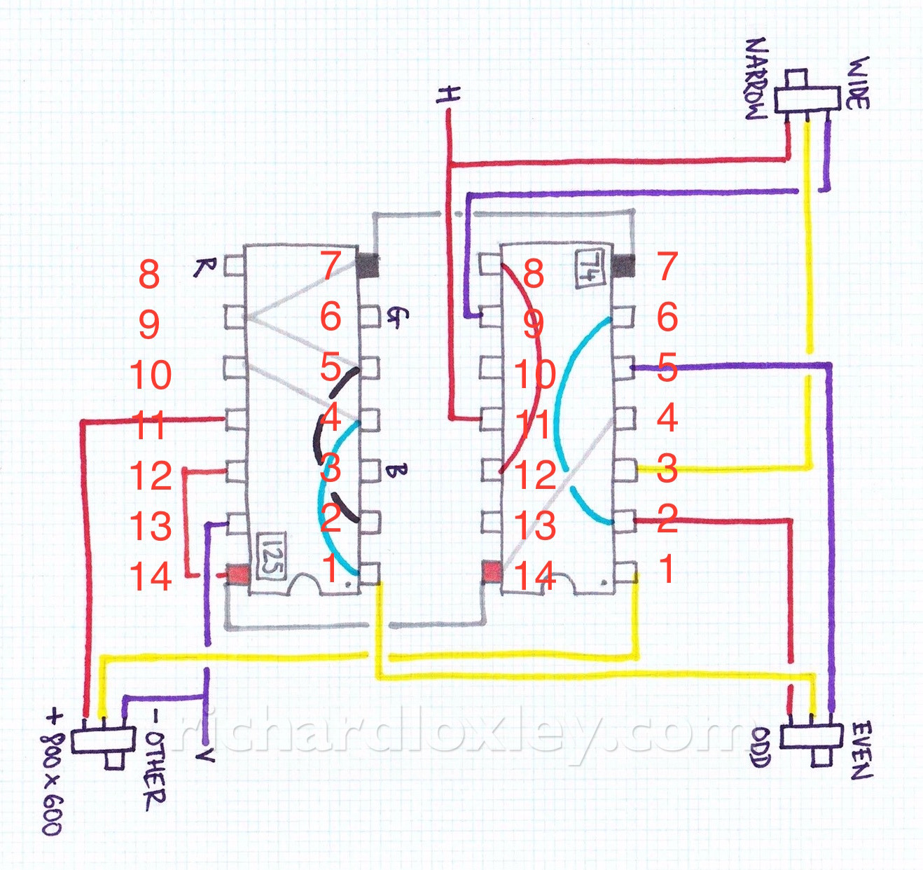
I won’t be using the “odd/even” switch as I don’t care which scanlines are blanked.
I will use the “800×600/other” resolution switch (for some reason the 800×600 VGA mode has sync pulses inverted, so the sync signal needs to go through a NOT gate to invert it – I wonder if the early VGA monitors used this to detect the resolution change?)
And I may use the “wide/narrow” switch, which changes between blanking every other line, and blanking pairs of lines (by using two flip-flops to count odd/even pairs). I hope to get the resolution scaled up to double height vertically (e.g. take the 200 visible pixels and 200 scanlines and double up to 400 visible pixels and 400 scanlines, i.e. 800 lines total) and then ‘window’ that within a higher resolution (e.g. 800 lines out of 960/1050/1080 VGA modes). If I can make that work, then I’ll need double-height scanlines :-)
So now to prototype it!
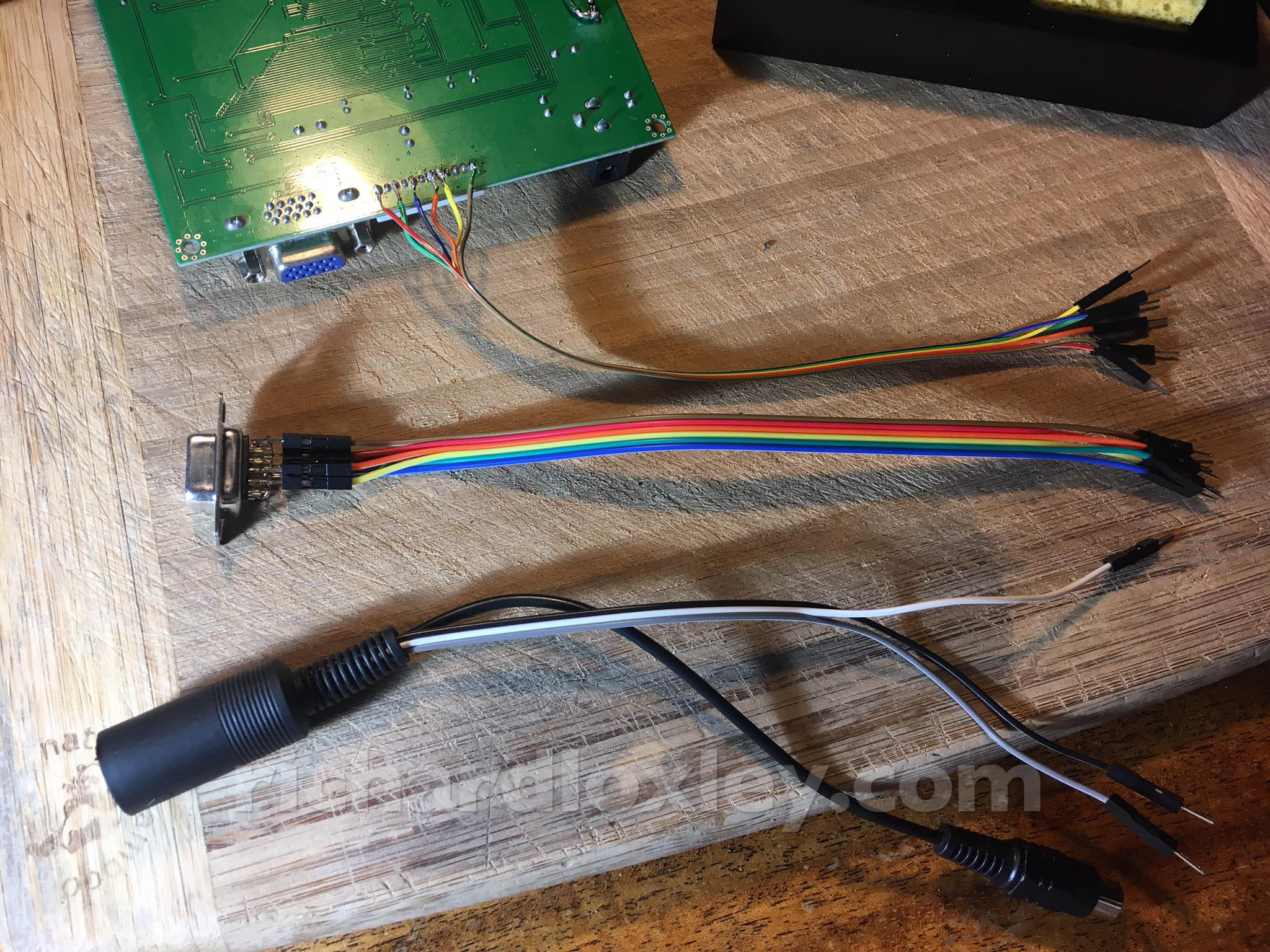
Here I’ve soldered a ribbon cable to the RGBHV (VGA) output of the video board, and another cable to a VGA socket to take the output to the edge of the case. That will allow me to attach the scanline generator to the output.
(Also shown is a cable with a DIN socket to attach to an Amstrad GT85 green-screen monitor. As a separate task I’ll be trying to get it to accept composite video from my Video Genie!)
The mess on this breadboard on the left is the simplest form of the scanline generator circuit:
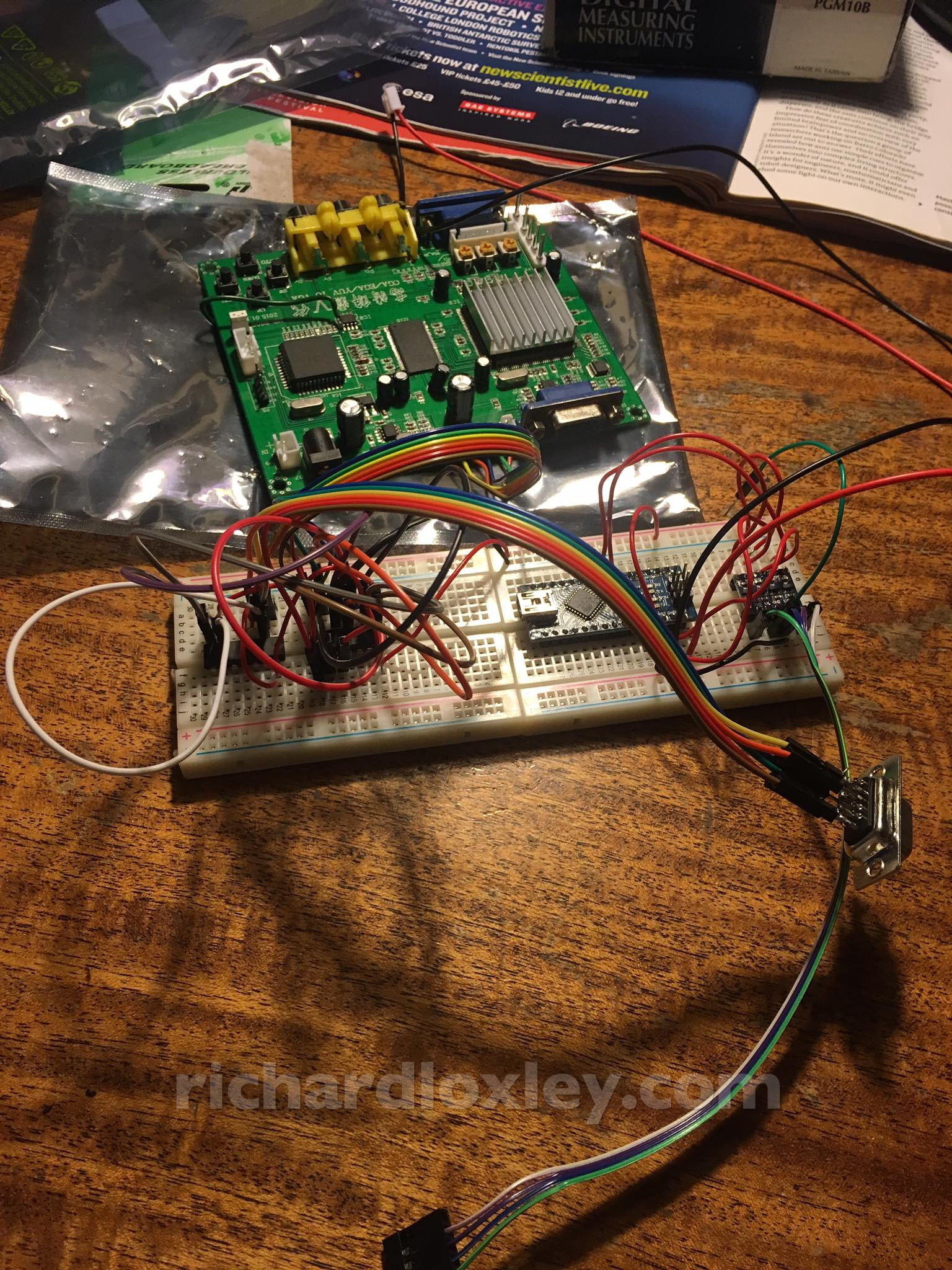
(On the right breadboard is the Arduino and level-shifter I used for my TV5725 experiments. I still need it as I’m using the Arduino’s 5v regulated output to power the scanline generator!)
I’m going to test this first before going for the more advanced version! I’ll be amazed if it works first time.
Well, consider myself amazed: my prototype scan line generator worked first time ![]()
I then tried the more advanced version (blank pairs of output lines, not single lines: useful for running in higher resolution displays). But I’ve broken it (lots of flickering, as if I’ve got a loose wire, which I probably have). I briefly get the wide scanlines if I hold a wire just right!
Not sure whether to fix it on the breadboard, or start soldering up a permanent version. The only thing is, I’d like to be able to switch this in software from the Arduino. But that means designing a mechanism to do that before building the final board.
I asked my knowledgeable friends for ideas to switch these data lines from an Arduino output, and eventually discovered what I needed was an “SPDT analogue switch“. I’d have never have thought to google for that!
I’m going to try the Vishay DG333ADJ-E3 (Analogue Switch Quad SPDT) which should work on 5v, is a 20 pin DIP package, and can control up to 4 two-way switches. £2.32 from RS. That should do all the switches on the scanline generator.
I did also find the ADG715, which controls 8 SPST switches via i2c, which would do everything and not tie up Arduino ports. But seemingly only available in surface mount packages, and I haven’t been able to find a DIP equivalent from other manufacturers either. Oh well.
Finally I started to design a veroboard circuit for everything so far. It’s not complete yet, and I’m sure stuff will change, but it’s a start!
It’s taken me a whole day! I’m squeezing in more than I should in the space available, but I’ve managed to get everything in without crossing wires!
Green dots are headers where I’ll connect to other boards.
Top left is the standalone sync stripper to generate a clean sync signal for the video board.
Bottom left is the Arduino that will control the video board via i2c, drive an LCD display, receive inputs from two rotary encoders, and control other bits of the circuits via the switches in the middle.
The middle two chips are analogue switches (a bit like relays) that turn things on and off when the Arduino tells it to.
The top analogue switch contains 4 single pole switches: 2 of them will activate buttons on the floppy drive, so I can hopefully control the floppy drive using one of the rotary encoders instead of push buttons. The third switch turns the power on and off to the scanline generator on the right.
The bottom analogue switch contains 4 double pole switches. I only use two of them, selecting narrow or wide scanlines, and inverting the sync signal for 800×600 screen resolutions.
The two chips on the right do the scanline generation. The bottom one is a flip-flop, that changes state every scanline (or every other scanline if wide is selected). The top one is essentially a load of transistors that will be triggered by the flip-flop, and connect the RGB lines to ground, forcing them to be black. (It also uses one of the gates to invert the sync signal if 800×600 mode is selected as that VGA mode has negative sync pulses for some reason).
I’ll need to do lots of checking before I solder this up! (I also don’t have the two analogue switches yet, but I can test the other stuff without them.)
Points I’ve noticed about the circuit that I need to address:
- I’ve designed all the chips to run off the Arduino 5v output (except the 1881 which can take anything as a power supply). But I also need a 5v supply for the floppy drive. I suspect that may exceed the capabilities of the Arduino. The regulator of the Arduino is rated at 1A, and the Arduino itself is unlikely to use more than 500mA, if that, so I might be ok. But it might be safer to build a separate voltage regulator circuit onto the board and drive everything off that.
- I was going to add sound emulation to the floppy emulator. Only a resistor and a transistor needed (and an external speaker), so I could just piggy back on the floppy board. But I might see if I can fit them in here. [Update: I’m now wondering about doing more extensive sound synthesis, but that needs more research.]
I’m still not sure whether to do a mega board like this, squeezing everything in, or do separate modular boards for each bit of functionality.