After a week’s holiday (including a very enjoyable visit to Spencer Owen‘s Nottingham Monthly Hardware Meetup) it’s time to get back to the Retro Challenge.
Most of the big tasks have now been done, so it was time to make a to-do list of all the little jobs left to do.
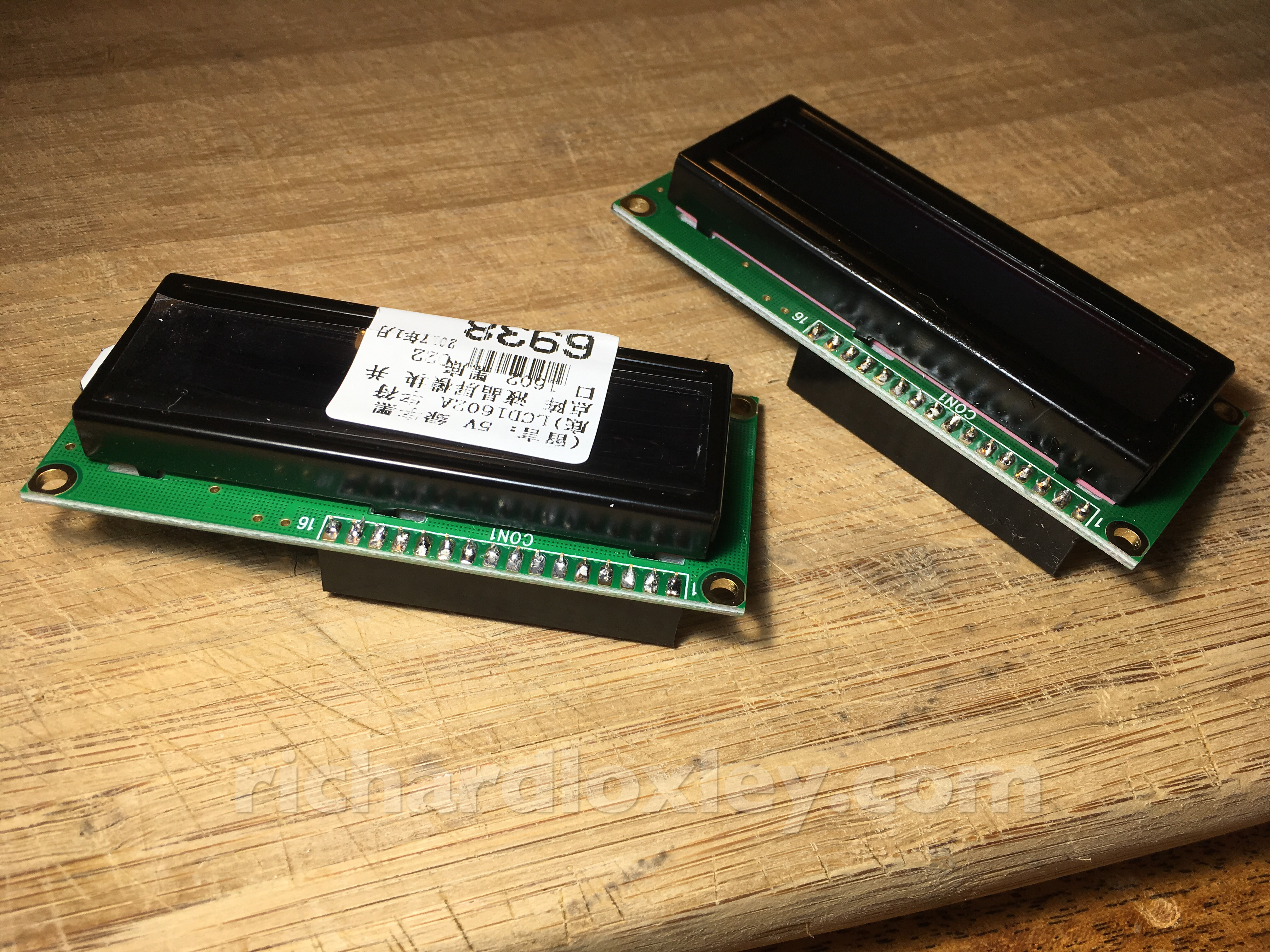
First off, a bit of soldering. I’d initially bought blue LCD displays as they were quickly available in the UK. I then ordered the correct green LCDs from China. Despite a claimed 30-50 days delivery from Aliexpress, they arrived while I was on holiday: so sometime between 21 and 27 days later – not bad.
A quick spot of soldering later:
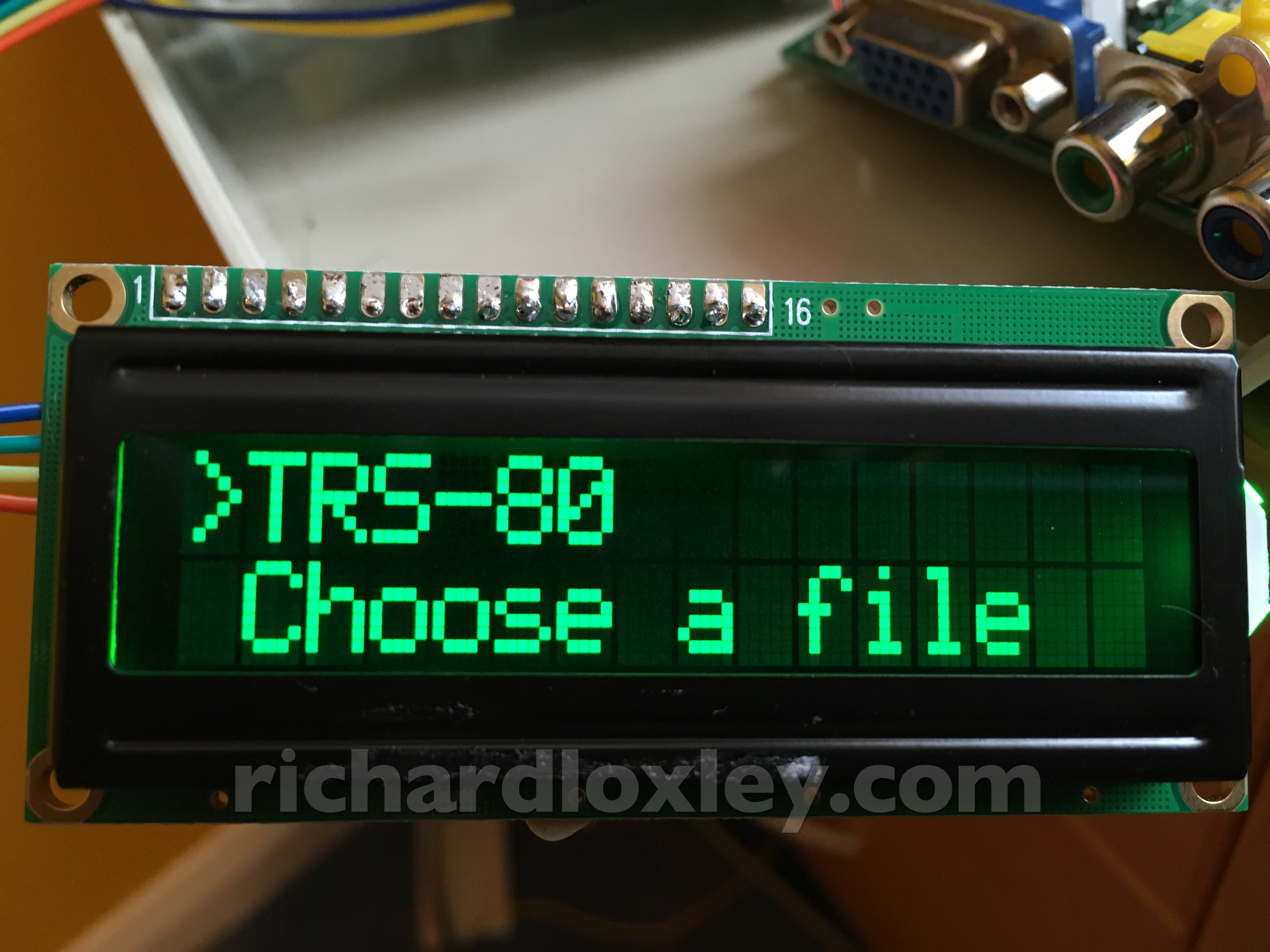
And I have a lovely retro display for the floppy drive emulator:
Next up, I solder on some interfacing wires to the floppy emulator’s control buttons. (I want to try controlling the UI via the Arduino).
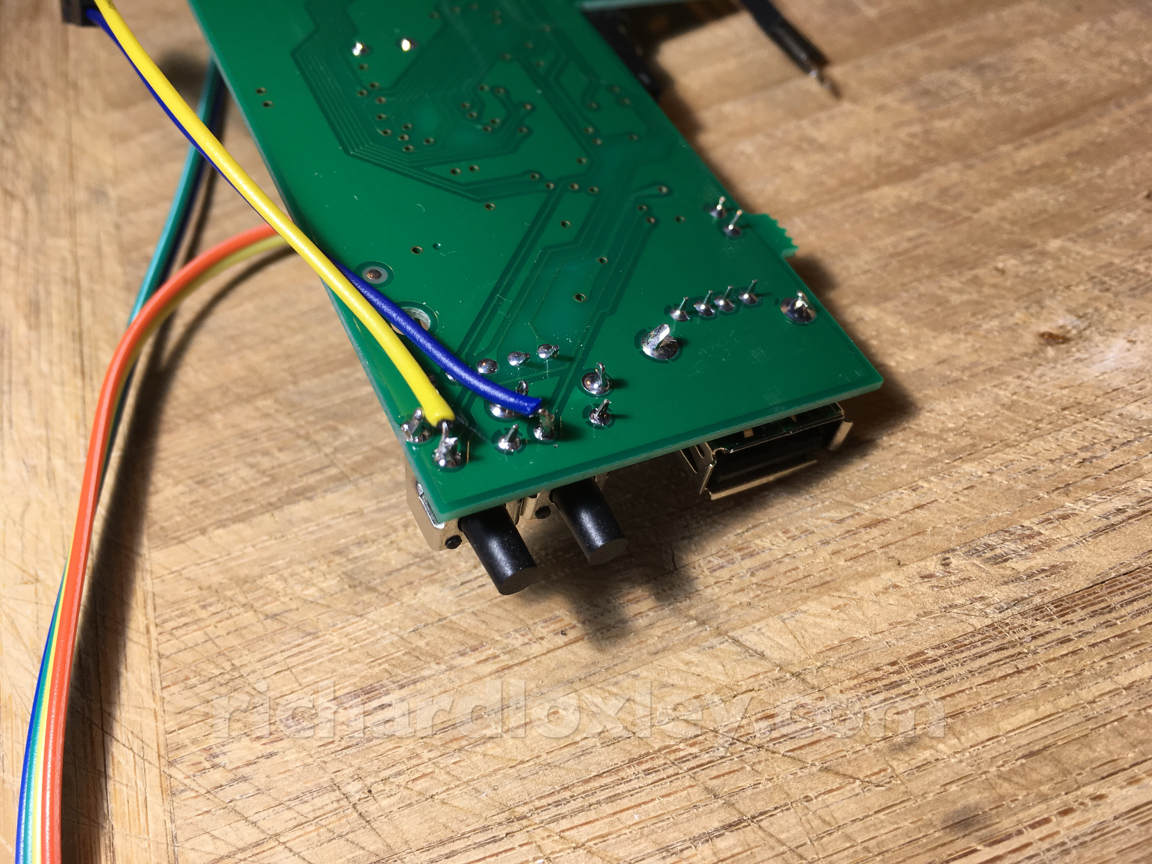
And now to do a bit more prototyping. But wait! I notice a problem: I’d previously had to solder on a green wire to a surface mounted IC to get access to the SDA i2c line (I’d broken the PCB trace trying to attach a header in the correct place).
In my travels the wire had come detached. No worries, I’ll re-solder it. I tried to make a better job of it this time, making the path neater, and making the solder joint more secure:
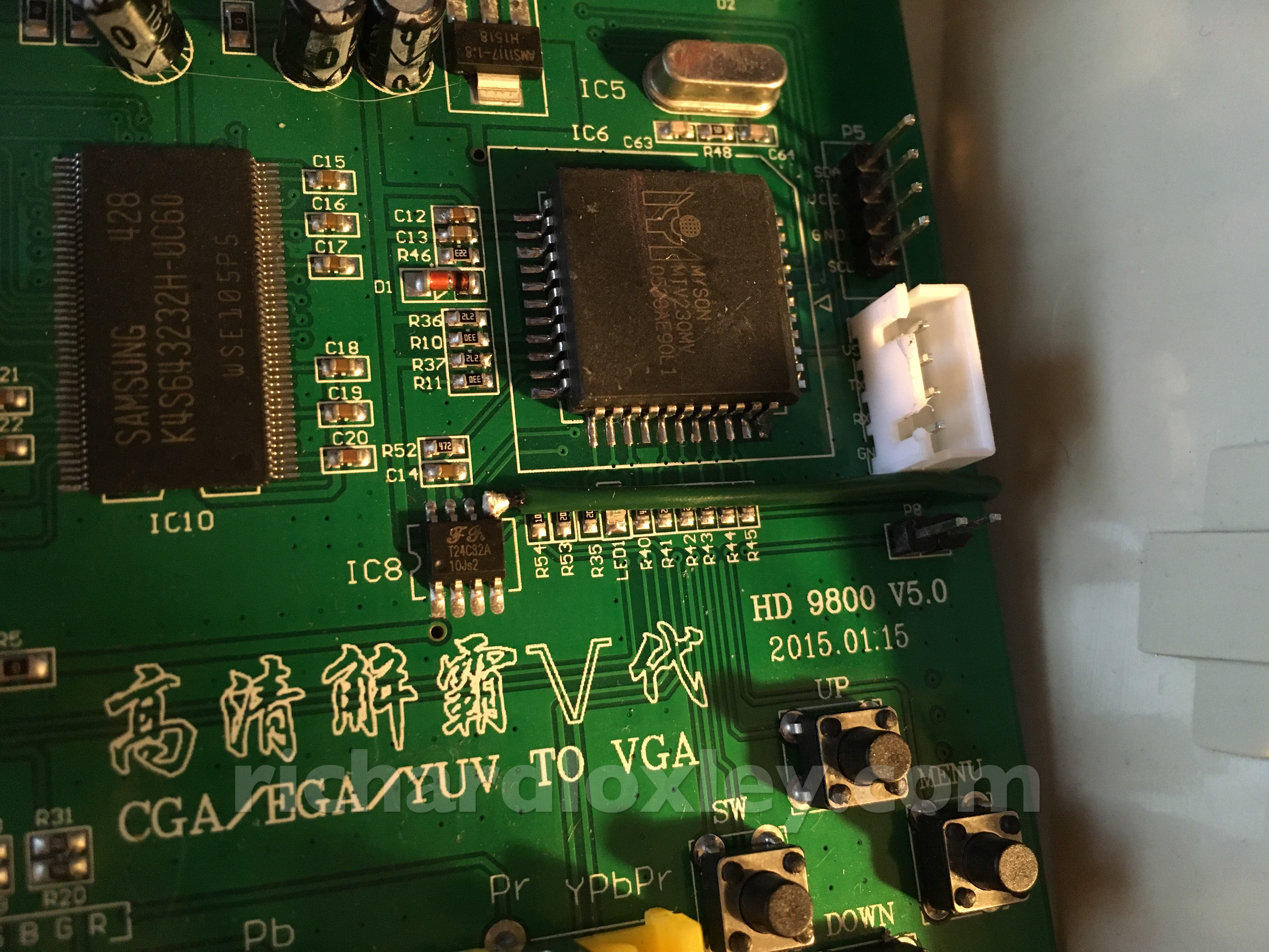
But in making the more secure joint, I had to hold the soldering iron on for longer. I then noticed slight discolouring of the corner of IC8 from the heat ![]()
I tried powering it on (without my Arduino mod connected). No boot up message, but I did get the on-screen display briefly when I pressed the Menu button. But then it disappeared, and won’t come back.
I then tried the Arduino mod, in case I’d just knackered the system-on-a-chip (which the Arduino bypasses). But all registers read as zeros now. I’ve probably knackered IC8 with heat damage (although it could be static damage elsewhere I suppose).
I’ll try a bit more debugging to make sure I’ve got the i2c wired up correctly, but I suspect I’ll have to buy another board. They’re £18 with 10 day delivery, or £13 with 20-40 day delivery. I might go for the slower delivery as Aliexpress has been pretty fast recently (only 13 days for the faster delivery), and I’ve already proved the concept with the HD9800 so can slot a new one in at the end of my project.
I could try repairing the board. IC8 is a T24C32A EEPROM. I can get a packet of similar ones for about £2 from China. But of course I could damage the new one with my soldering skills, unless I used a socketed version. And I don’t know whether the EEPROM is just used to store temporary values written from elsewhere, or whether it was preprogrammed. If the latter, then a new version wouldn’t help.
I’ve tried to see if schematics are available to work out how it’s used. But a search for “HD9800 schematic” turns up nothing – but does include 30 references to my own website where I’ve blogged about it! It seems I am now a primary source for information about it ![]()
Hmm, I’ve been doing a bit more research on IC8 (the i2c EEPROM).
According to its data sheet it has an i2c address in binary of 1010abc0 where a,b,c are set by three input pins. On this board those pins are connected to ground, giving it an address of 10100000 or 0xA0.
The i2c address I’ve been using to set the registers on the TV5725 is 0x2E (which is confirmed by the TV5725 manual). The TV5725 manual also makes no mention of an i2c EEPROM to make it work. So I don’t think IC8 is used at all for my direct access of the TV5725.
The other chips on the board include a Samsung SDRAM chip (which is mentioned in the TV5725 manual in reference to the deinterlacing process). And a MTV230M system on a chip which includes an on-screen display. The latter is what I’m bypassing, and from its data sheet it can access i2c devices.
So my theory is that the MTV230M would normally set the i2c registers on the TV5725 in response to the on-screen menus. I hypothesise that it also uses the IC8 EEPROM to store configuration parameters when powered off.
All this makes me think that if I have broken IC8, it shouldn’t affect my ability to squirt values into the TV5725 registers via i2c from the Arduino.
I need to really methodically check what I’m doing with the Arduino before I write off this board!
Woohoo! Got it working again (I think).
I spent two afternoons of methodical debugging (using only a multimeter – an oscilloscope would have made it so much easier – that’s next on my wish list).
Eventually I found the SDA line on the i2c interface was at about 1.5v. It should only be 0v or 3.3v as it’s a digital signal. It remained at about 1.5v even with everything disconnected. That’s not right. The HD9800 is supposed to have pull-up resistors on the i2c lines to keep them at 3.3v if nothing else is connected.
So have I just broken the pull-up resistor? I did drop a blob of solder on a component near IC8 (either a resistor or capacitor), but it brushed off easily so though nothing of it. Even so I wouldn’t have thought that would have done anything. Or maybe IC8 includes an internal pull-up resistor and the heat damage killed it?
Anyway, I’ve added an external 4.7k pull-up resistor between SDA and 3.3v:
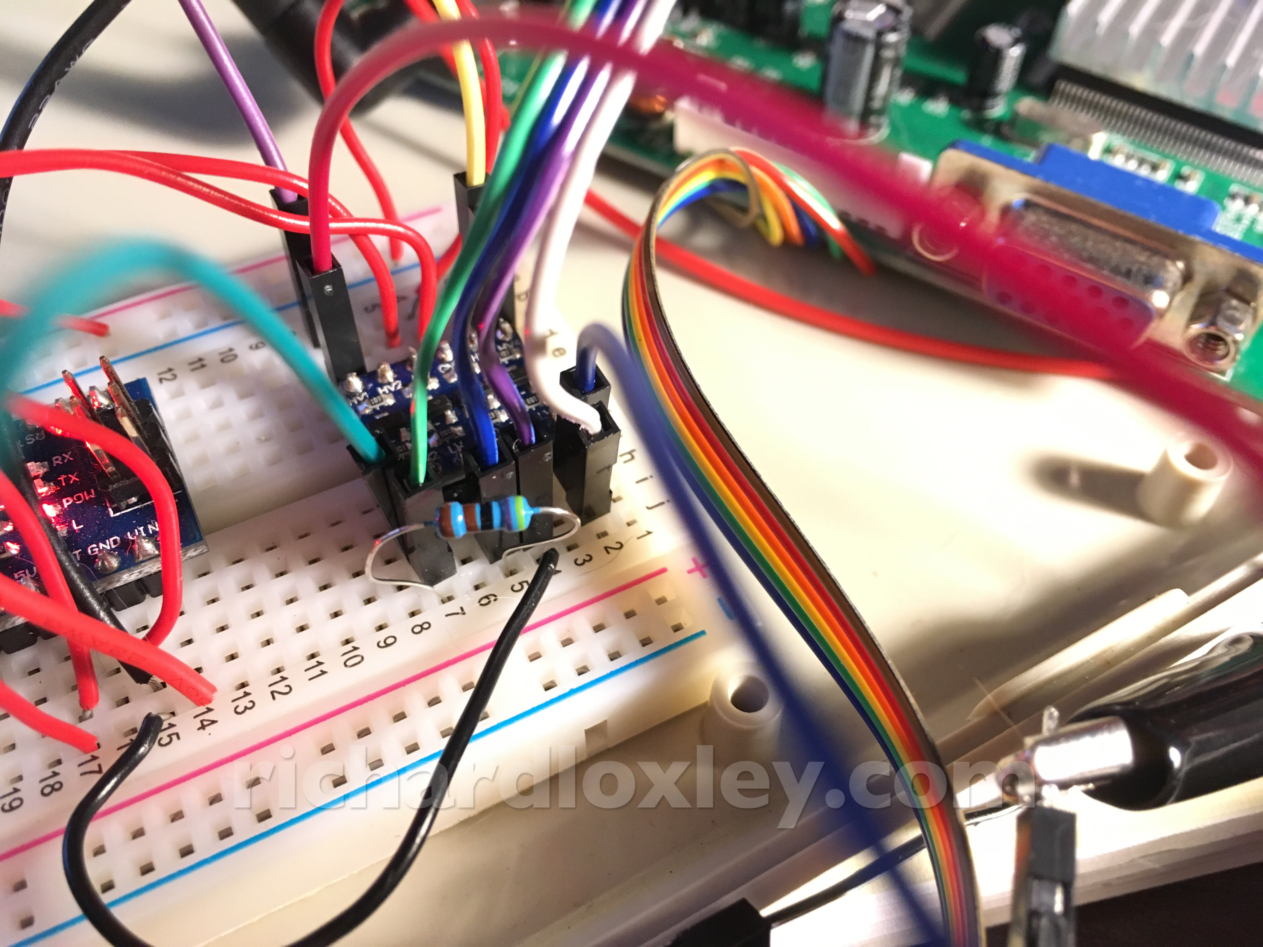
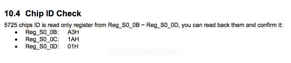
Now my Arduino is successfully communicating with the TV5725 again, and has read out the chip ID correctly ![]()
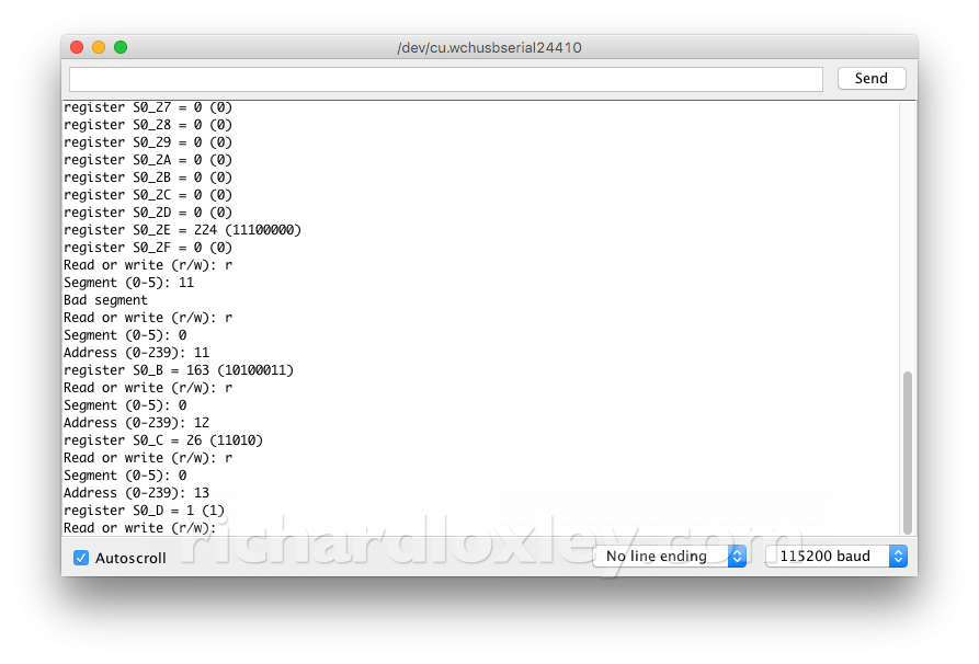
So now I’m back to the same point I was at two days ago. But at least I can move forward now!