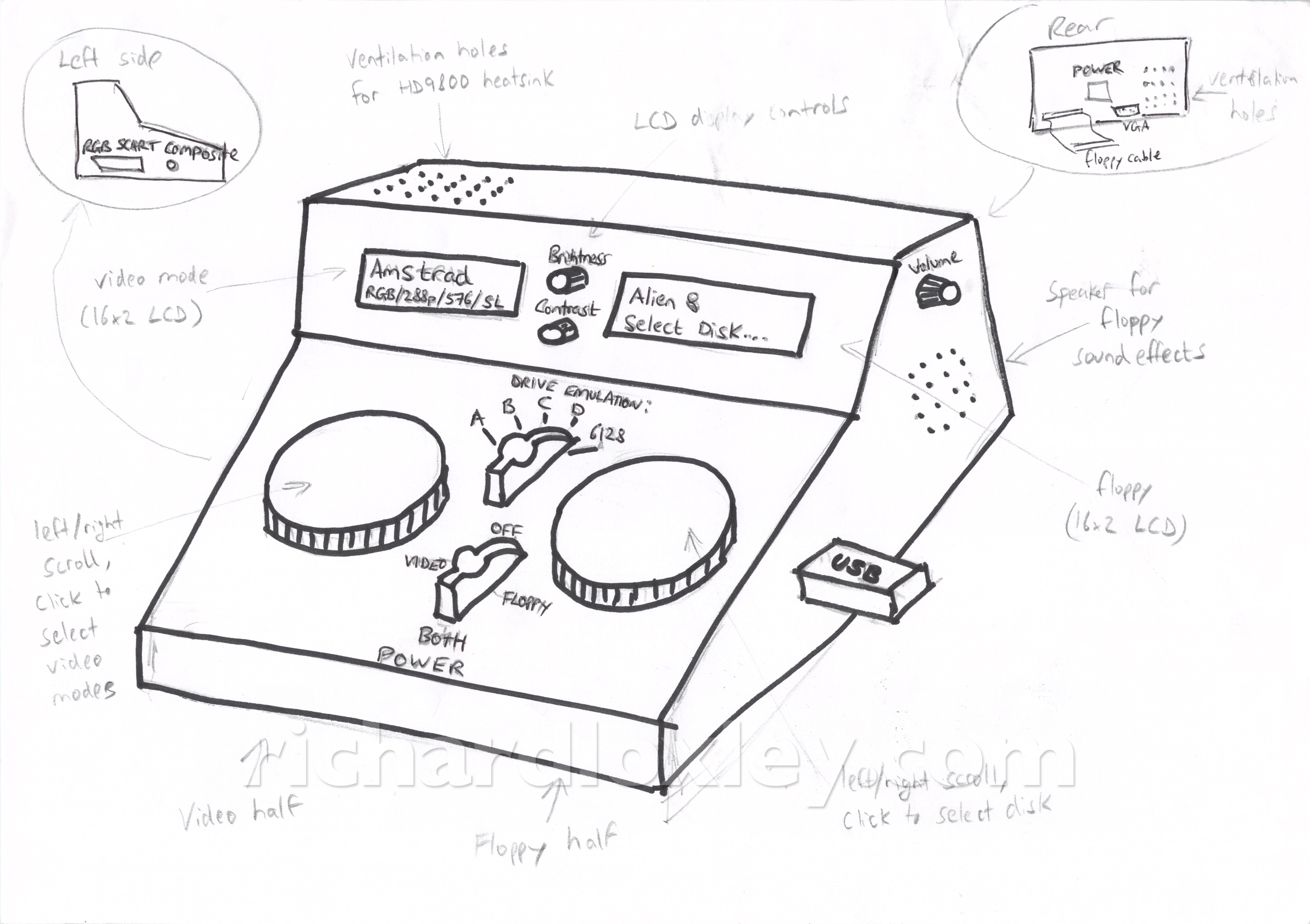
It’s now time to start prototyping the user interface for my RetroMatic 2000 box. As a reminder, the box will have two functions: a video converter to allow an 8-bit micro to be used on a modern monitor, and a USB stick floppy drive emulator.
The plan is to have each function controlled by a rotary-encoder (with a click button) with feedback via 16×2 LCD displays:
So today’s job was to get the rotary encoders working, and connect an LCD display to my Arduino Nano which will control everything.
I’ve never worked with a 1602 LCD display before. I have done rotary encoders, but only on an ESP8266, so my code needed converting somewhat to work on an Arduino, which has a different interrupt model.
Here’s the connection diagram I sketched up:
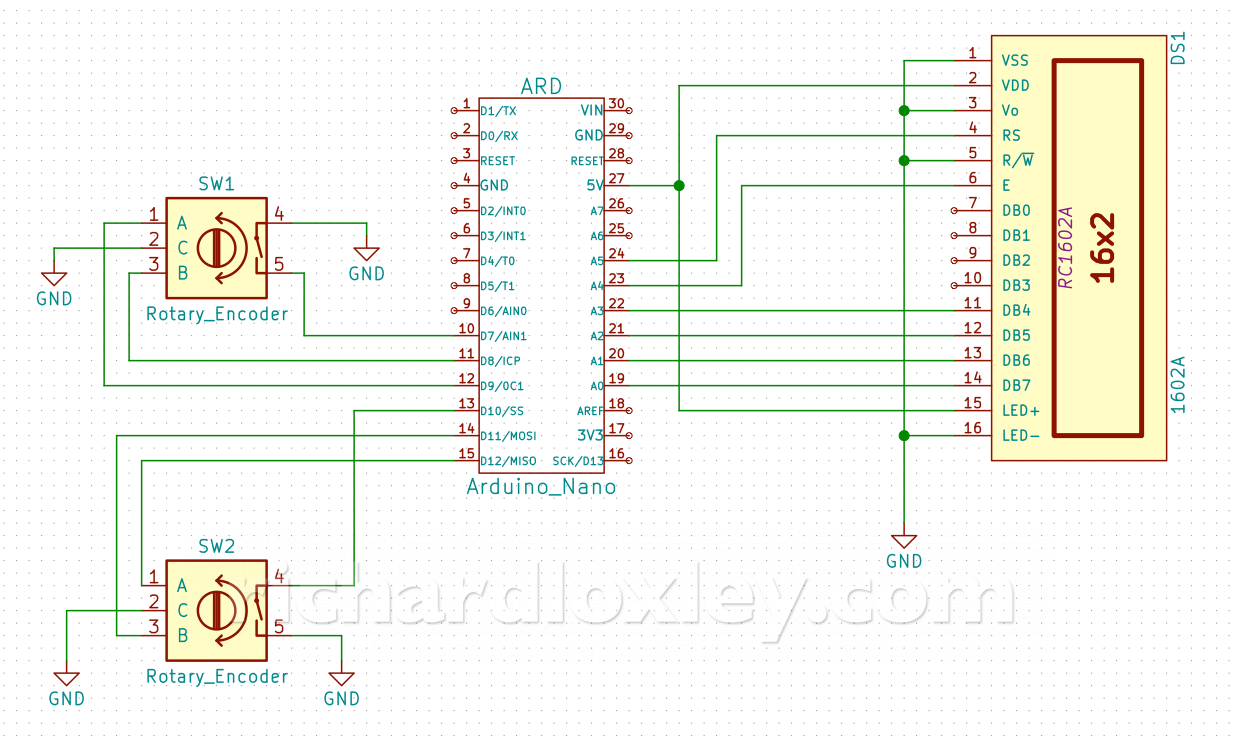
The 1602 LCD display is using the 4-bit data transfer mode. I’ve hard-wired the read/write pin to ground (write mode), and I’ve hard-wired the contrast to ground as experiments showed that gave an acceptable level of contrast for this display.
I used a multimeter to check that the LED backlight had a resistor already in series with it on the board, so I didn’t need an external resistor. That’s then just connected to 5v.
All this means I only need 6 pins on the Arduino to control the LCD. I’m using the LiquidCrystal library on the Arduino, so the code is very straightforward to drive it.
The rotary encoder inputs use internal pull-up resistors on the Arduino so they can just be connected to ground.
I had to read-up a bit on the Arduino interrupt model. I’m used to the ESP8266 wifi board, that allows arbitrary pin-change interrupt handlers to be attached to any pin. I had read that the Arduino only allows that on 2 specific pins, but I’d also read that it was possible to use as many pins as you liked. Which was correct? I needed interrupt handlers on 4 pins to use 2 rotary encoders.
It turned out both answers were kind of correct!
The Arduino allows full control (rising/falling/changing/etc) on only two pins, with high priority on the interrupt. But you can also have lower priority interrupts on any pin, the catch being they are only “change” interrupts, and the same handler must be used for each bank of pins on an Arduino input port. So you can do the same as the ESP8266, you just have to do some of the heavy lifting yourself in your interrupt handler.
I found a great guide to all things to do with Arduino interrupts. Of particular use to me were the sections on pin change interrupts and correctly handling mutual exclusion when accessing multi-byte volatile variables.
I’d learned when developing my ESP8266 rotary encoder code that speed is essential, so had used macros extensively, and used direct memory access to pins rather than the Arduino libraries (function calls add a considerable overhead to a fast interrupt handler).
I followed the same model in developing the pure Arduino version. Check out the code at the end of this post if you want a closer look.
And here’s a simple test of reading the encoder positions and displaying them on the LCD module:
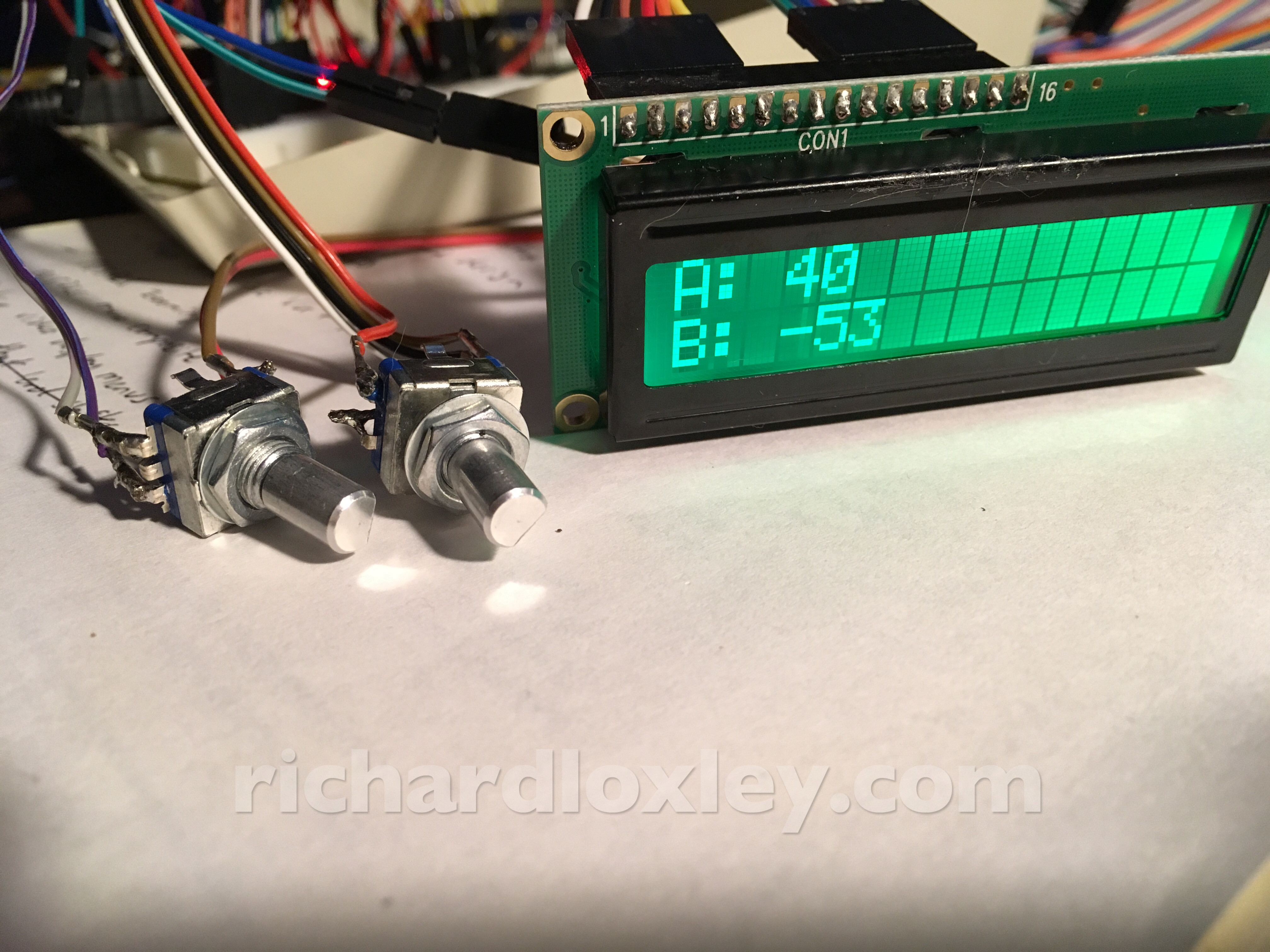
And here’s it in action:
The code
//
// rotary encoder stuff
//
// Good tutorial on Arduino interrupts here: http://gammon.com.au/interrupts

#define ENCODER_PIN_1_CLICK         7
#define ENCODER_PIN_1_A             8
#define ENCODER_PIN_1_B             9
#define GET_ENCODER_PINS_1          (PINB & 0b11)              // pins D8 and D9 are bits 0 and 1 of PINB
#define INTERRUPT_PCMSK_GROUP_1     PCMSK0                     // port B is group 0
#define INTERRUPT_PCIFR_GROUP_1     PCIF0                      // port B is group 0
#define INTERRUPT_PCICR_GROUP_1     PCIE0                      // port B is group 0
#define INTERRUPT_1_A               PCINT0                     // pin D8
#define INTERRUPT_1_B               PCINT1                     // pin D9

#define ENCODER_PIN_2_CLICK         10
#define ENCODER_PIN_2_A             11
#define ENCODER_PIN_2_B             12
#define GET_ENCODER_PINS_2          ((PINB & 0b11000) >> 3)    // pins D11 and D12 are bits 3 and 4 of PINB
#define INTERRUPT_PCMSK_GROUP_2     PCMSK0                     // port B is group 0
#define INTERRUPT_PCIFR_GROUP_2     PCIF0                      // port B is group 0
#define INTERRUPT_PCICR_GROUP_2     PCIE0                      // port B is group 0
#define INTERRUPT_2_A               PCINT3                     // pin D11
#define INTERRUPT_2_B               PCINT4                     // pin D12

// save register state (including interrupt state); turn off interrupts; execute code; restore register (including interrupt state)
// http://gammon.com.au/forum/?id=11488&reply=7#reply7
#define MUTEX(code)    { byte oldSREG = SREG; noInterrupts(); code; SREG = oldSREG; }

volatile byte rotaryEncoderState1 = 0;
volatile int rotaryEncoderErrors1 = 0;
volatile int rotaryEncoderPosition1 = 0;

volatile byte rotaryEncoderState2 = 0;
volatile int rotaryEncoderErrors2 = 0;
volatile int rotaryEncoderPosition2 = 0;

ISR (PCINT0_vect)
{
    // handle pin change interrupt for D8 to D13 here
    // http://gammon.com.au/forum/?id=11488&reply=6#reply6

    byte newState1 = GET_ENCODER_PINS_1;
    byte sum1  = (rotaryEncoderState1 << 2) | newState1; //adding it to the previous encoded value

    if (sum1 == 0b1101 || sum1 == 0b0100 || sum1 == 0b0010 || sum1 == 0b1011)
    {
        rotaryEncoderPosition1++;
    }
    else if (sum1 == 0b1110 || sum1 == 0b0111 || sum1 == 0b0001 || sum1 == 0b1000)
    {
        rotaryEncoderPosition1--;
    }
    else if (sum1 == 0b1100 || sum1 == 0b0110 || sum1 == 0b0011 || sum1 == 0b1001)
    {
        rotaryEncoderErrors1++;
    }

    rotaryEncoderState1 = newState1;


    byte newState2 = GET_ENCODER_PINS_2;
    byte sum2  = (rotaryEncoderState2 << 2) | newState2; //adding it to the previous encoded value

    if (sum2 == 0b1101 || sum2 == 0b0100 || sum2 == 0b0010 || sum2 == 0b1011)
    {
        rotaryEncoderPosition2++;
    }
    else if (sum2 == 0b1110 || sum2 == 0b0111 || sum2 == 0b0001 || sum2 == 0b1000)
    {
        rotaryEncoderPosition2--;
    }
    else if (sum2 == 0b1100 || sum2 == 0b0110 || sum2 == 0b0011 || sum2 == 0b1001)
    {
        rotaryEncoderErrors2++;
    }

    rotaryEncoderState2 = newState2;
}

/*
ISR (PCINT1_vect)
{
// handle pin change interrupt for A0 to A5 here
}

ISR (PCINT2_vect)
{
// handle pin change interrupt for D0 to D7 here
}
*/

int getRotaryEncoderPosition1()
{
    int pos;
    MUTEX(pos = rotaryEncoderPosition1)
    return pos / 4;
}

void resetRotaryEncoderPosition1()
{
    MUTEX(rotaryEncoderPosition1 = 0)
}

int resetRotaryEncoderErrors1()
{
    int errors;
    MUTEX(errors = rotaryEncoderErrors1; rotaryEncoderErrors1 = 0)
    return errors;
}

bool isClicked1()
{
    return (digitalRead(ENCODER_PIN_1_CLICK) == LOW);
}

int getRotaryEncoderPosition2()
{
    int pos;
    MUTEX(pos = rotaryEncoderPosition2)
    return pos / 4;
}

void resetRotaryEncoderPosition2()
{
    MUTEX(rotaryEncoderPosition2 = 0)
}

int resetRotaryEncoderErrors2()
{
    int errors;
    MUTEX(errors = rotaryEncoderErrors2; rotaryEncoderErrors2 = 0)
    return errors;
}

bool isClicked2()
{
    return (digitalRead(ENCODER_PIN_2_CLICK) == LOW);
}

void setUpRotaryEncoder()
{
    // set inputs
    pinMode(ENCODER_PIN_1_A, INPUT_PULLUP);
    pinMode(ENCODER_PIN_1_B, INPUT_PULLUP);
    pinMode(ENCODER_PIN_1_CLICK, INPUT_PULLUP);
    pinMode(ENCODER_PIN_2_A, INPUT_PULLUP);
    pinMode(ENCODER_PIN_2_B, INPUT_PULLUP);
    pinMode(ENCODER_PIN_2_CLICK, INPUT_PULLUP);

    // record initial state
    rotaryEncoderState1 = GET_ENCODER_PINS_1;
    rotaryEncoderState2 = GET_ENCODER_PINS_2;

    // set pins we're interested in
    INTERRUPT_PCMSK_GROUP_1 |= bit (INTERRUPT_1_A);
    INTERRUPT_PCMSK_GROUP_1 |= bit (INTERRUPT_1_B);
    INTERRUPT_PCMSK_GROUP_2 |= bit (INTERRUPT_2_A);
    INTERRUPT_PCMSK_GROUP_2 |= bit (INTERRUPT_2_B);

    // clear any outstanding interrupts
    PCIFR |= bit (INTERRUPT_PCIFR_GROUP_1);
    PCIFR |= bit (INTERRUPT_PCIFR_GROUP_2);

    // enable pin change interrupts for groups
    PCICR |= bit (INTERRUPT_PCICR_GROUP_1);
    PCICR |= bit (INTERRUPT_PCICR_GROUP_2);
}