This is part of a series of posts for the Retro Challenge 2018/04. See my index page for the other posts.
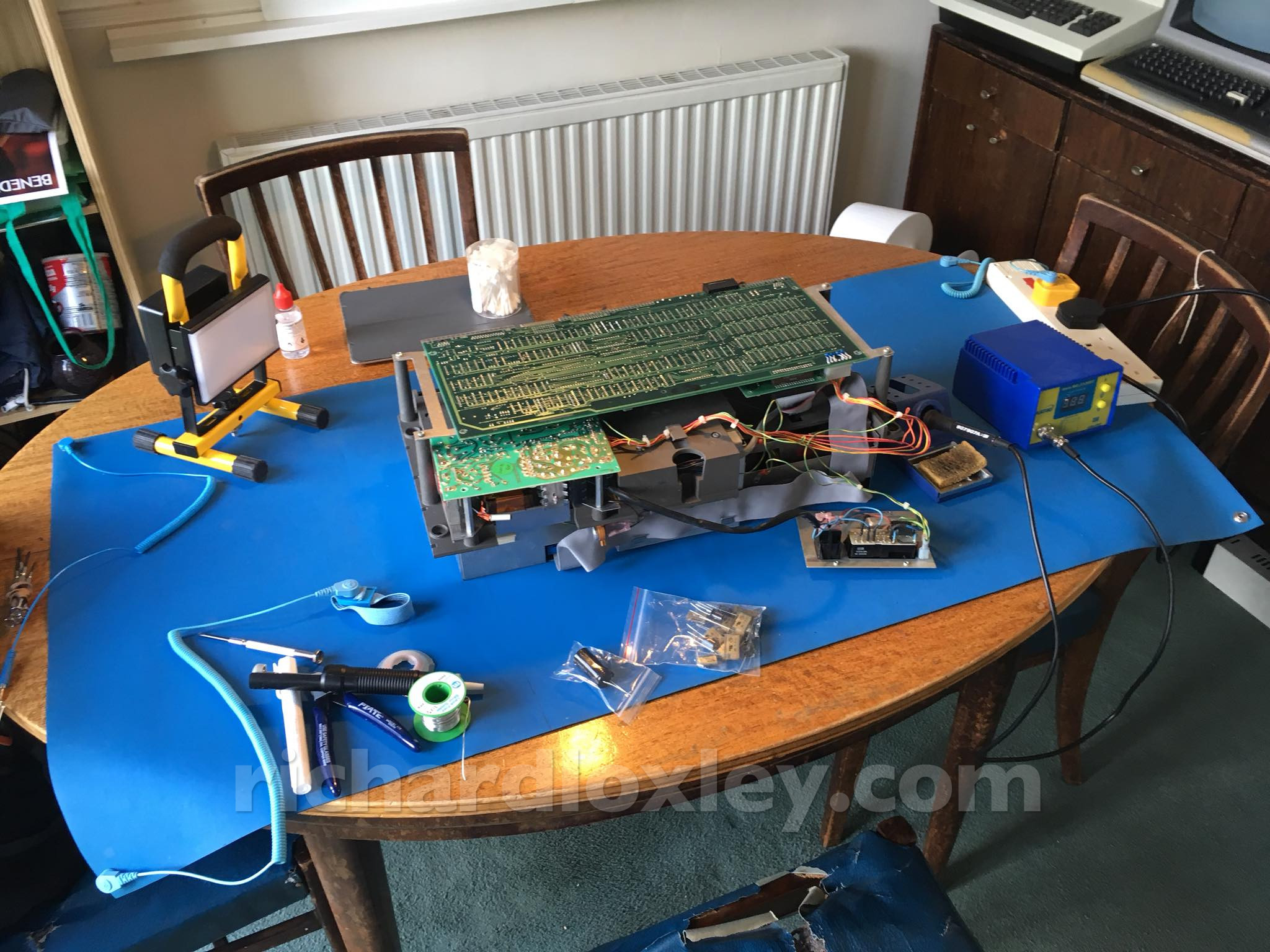
My spare capacitors from eBay had arrived, so I was ready to service the Osborne 1.
(With a glimpse of my Commodore PET and TRS-80 in the background!)
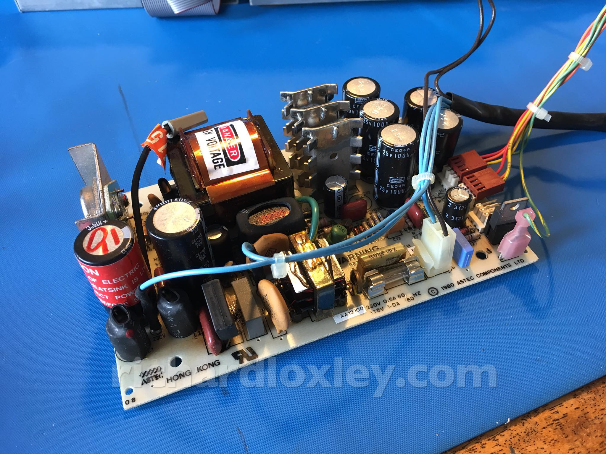
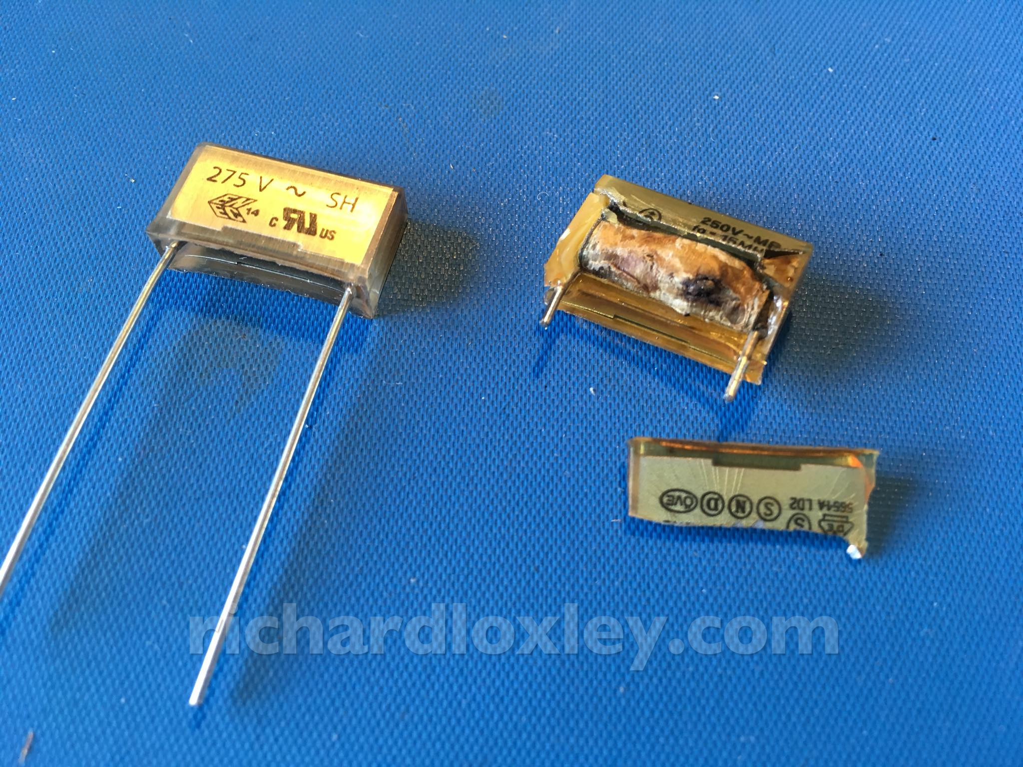
First I’m going to replace the disintegrating capacitor in the power supply.
Spot the difference!
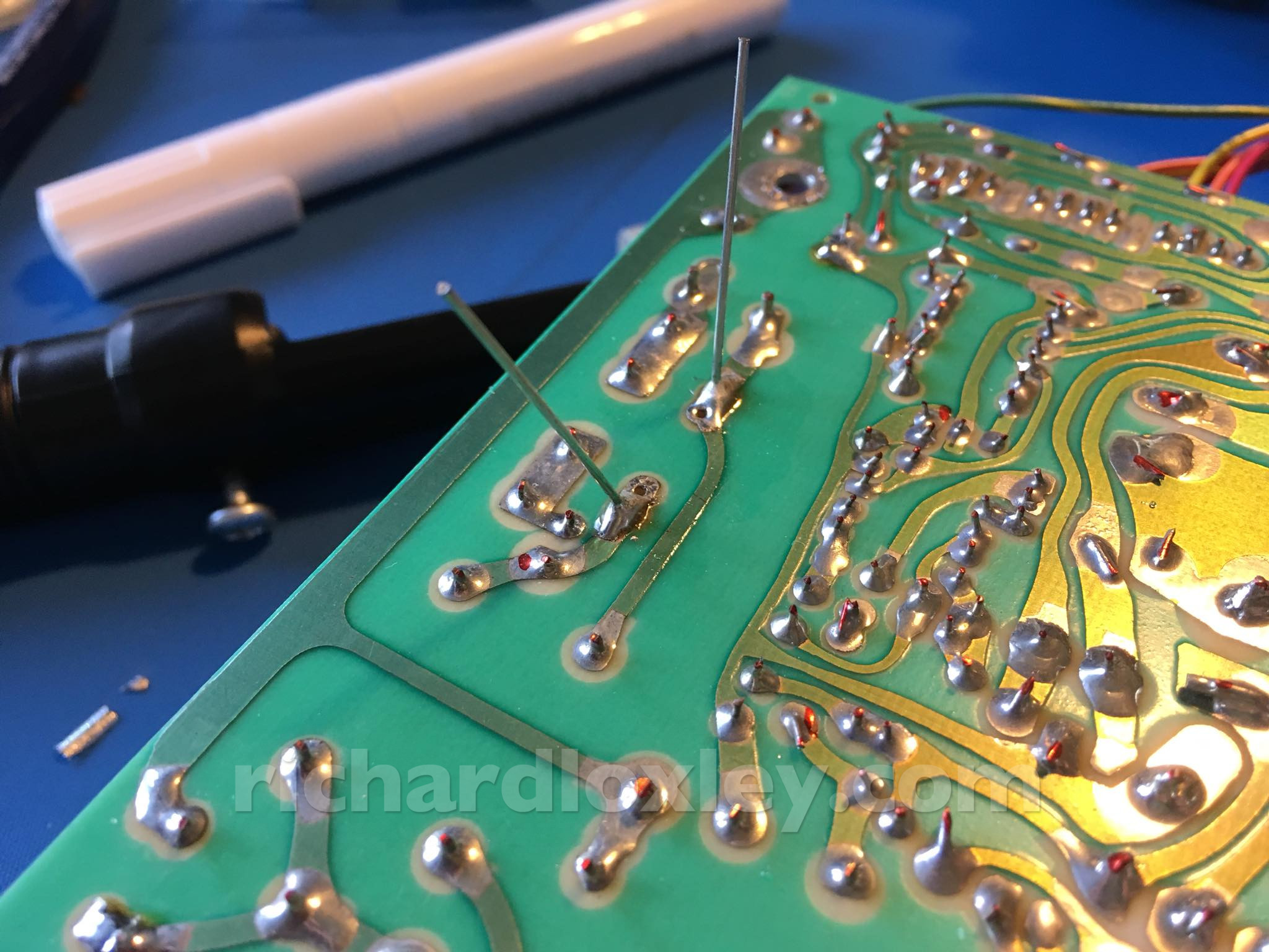
Soldering the new one in place.
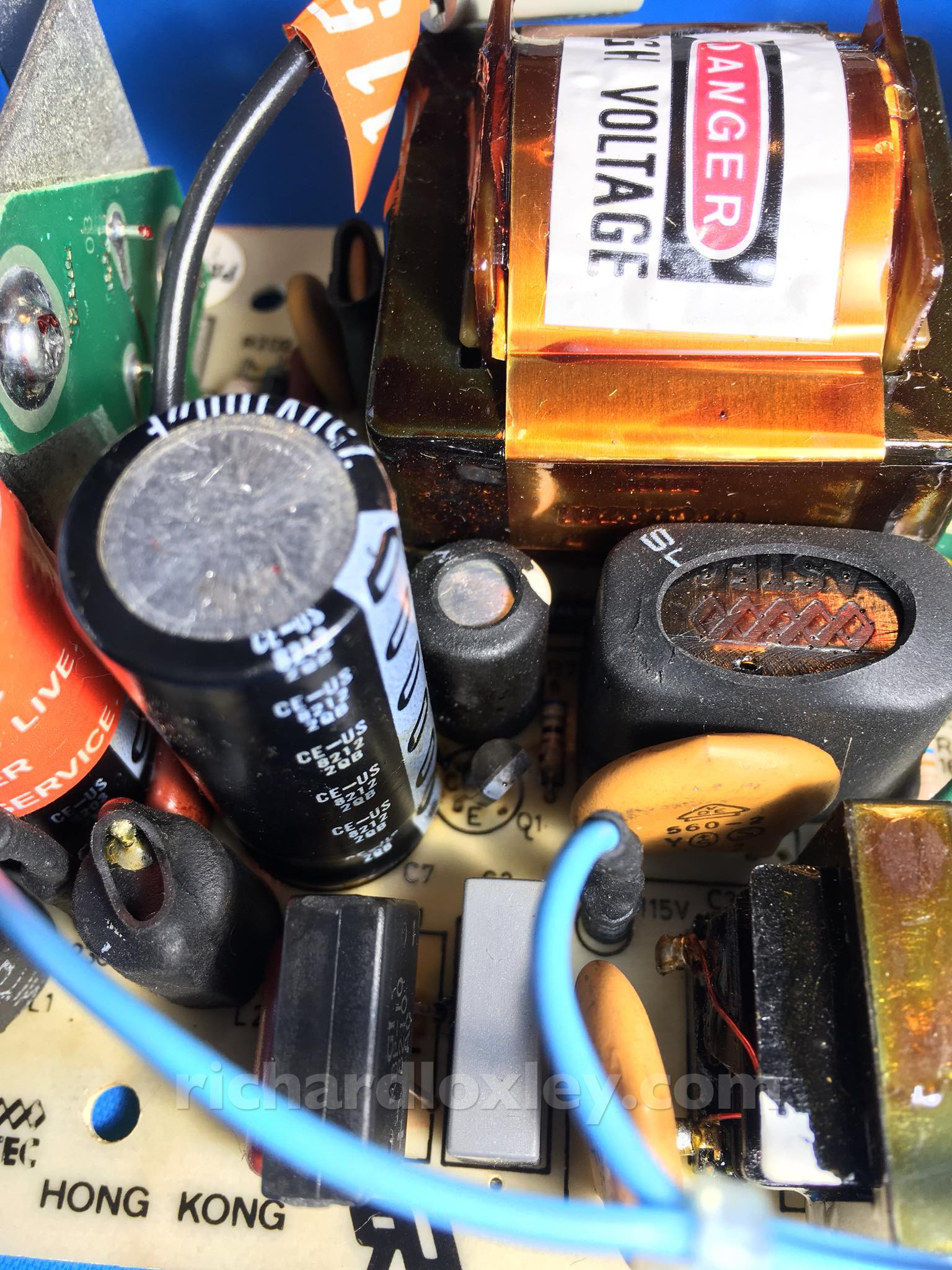
I was worried about this big cylindrical capacitor as it had electrolyte all over the bottom half. I wasn’t sure if it was leaking, or if it was residue from when the rectangular X capacitor exploded (the light grey is a replacement by a previous owner):
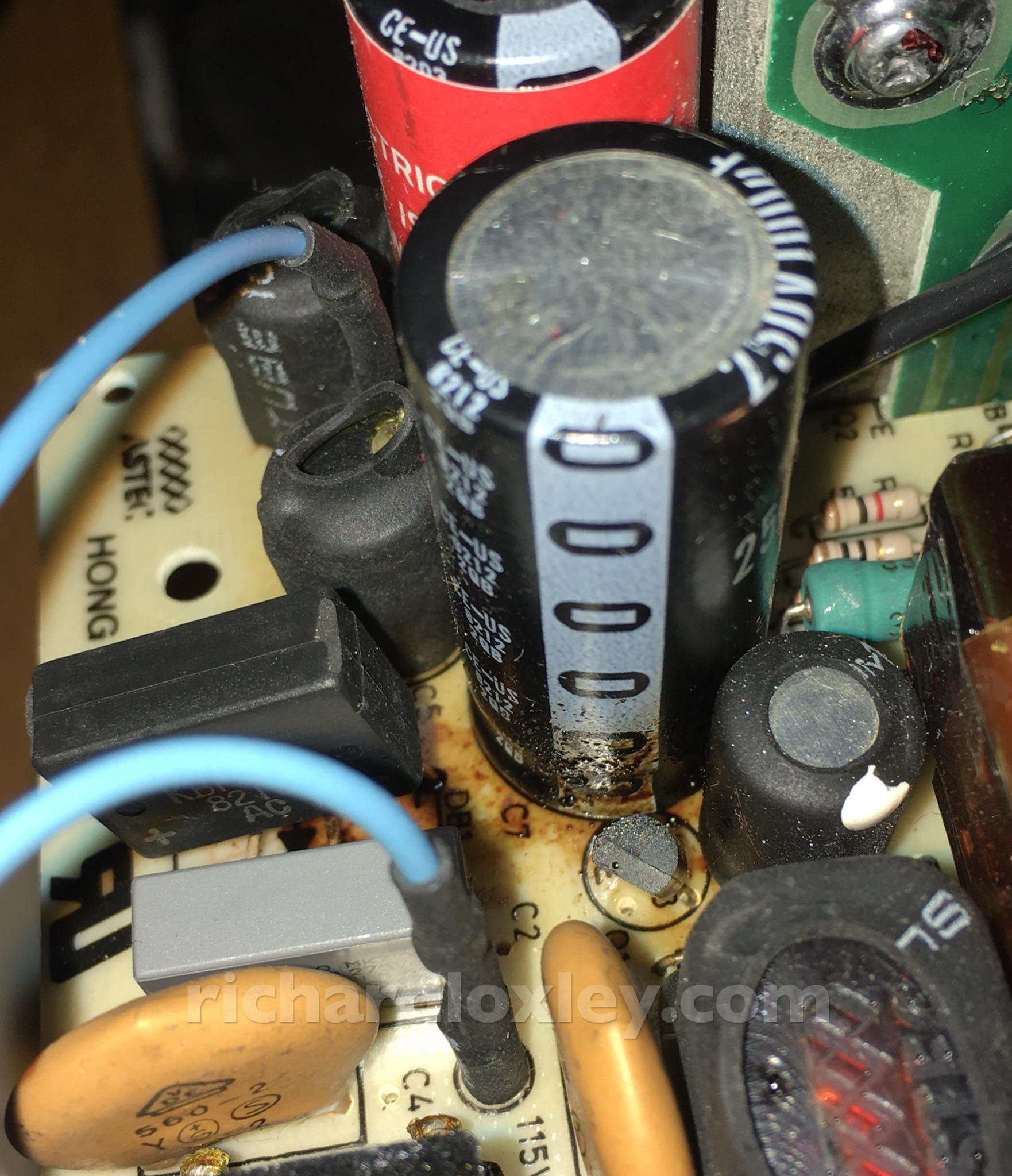
I cleaned up the outside of the capacitor with alcohol and a cotton bud. No sign of damage, so I’m leaving it be. I had bought a replacement, but it was only £1.88.
I’m also leaving the other X capacitors that have already been replaced, as there is no sign of failure.
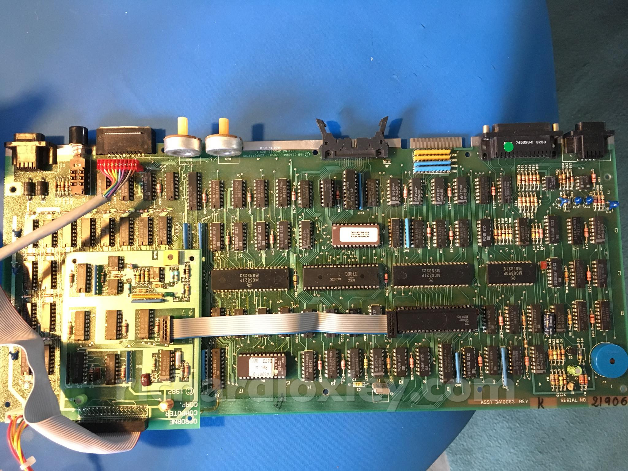
Here’s the main board of the Osborne. A remarkably simple computer:
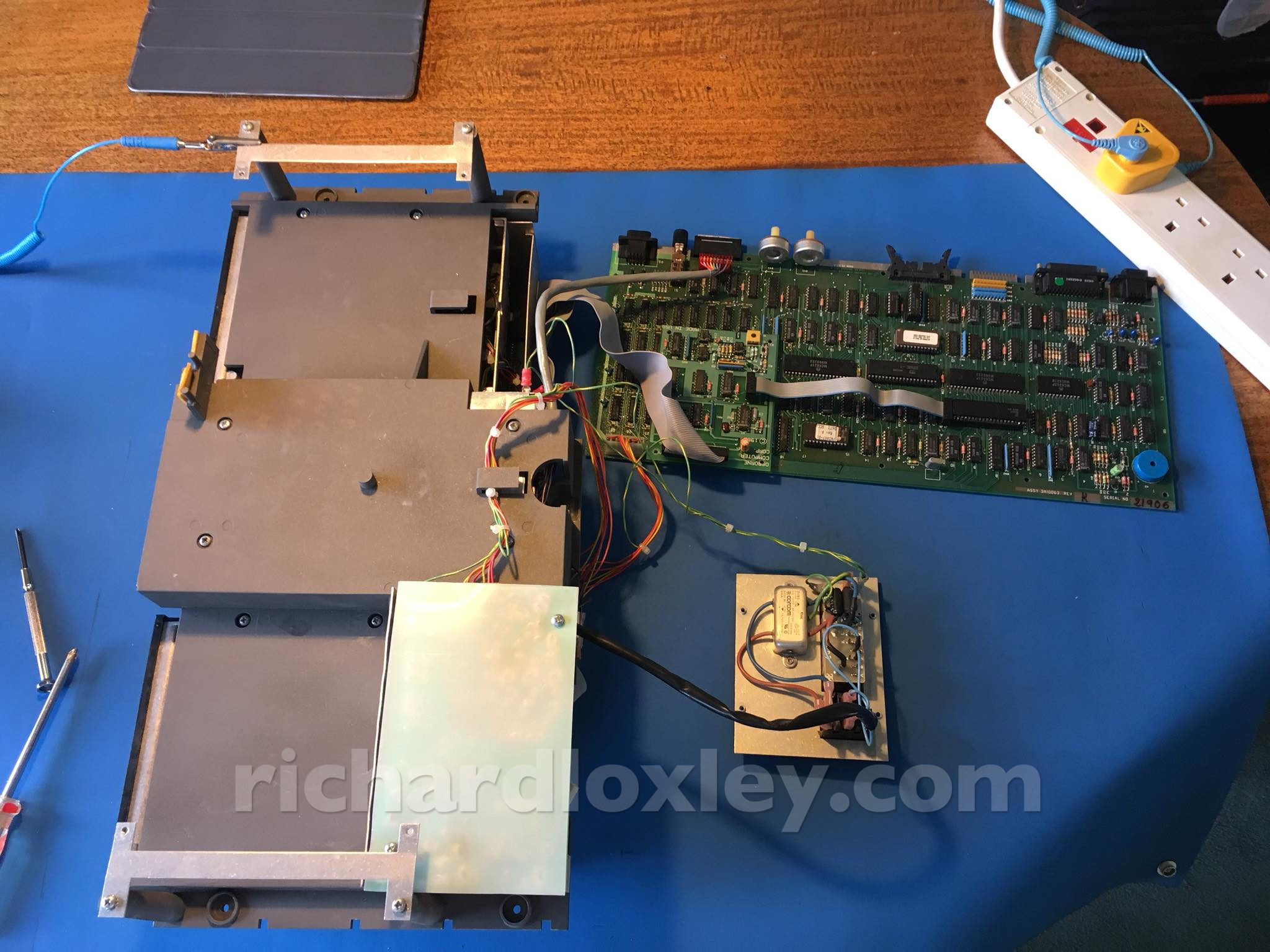
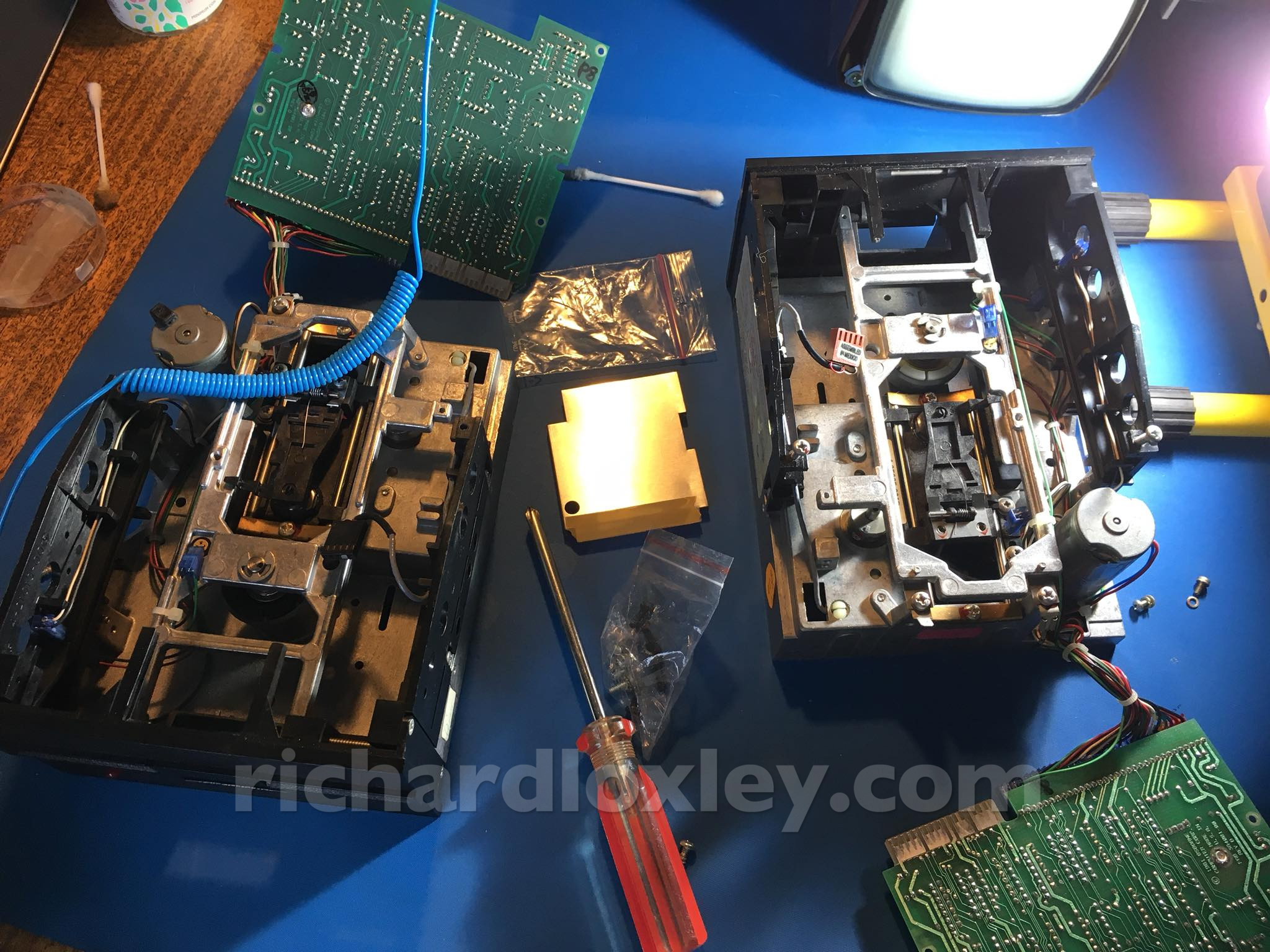
Now I’m taking out the floppy drives to clean and service them before putting any media in there which might get damaged:
The drive belt looks good. Before reassembling the drives I powered them up and used the strobe pattern to check the rotation speed.
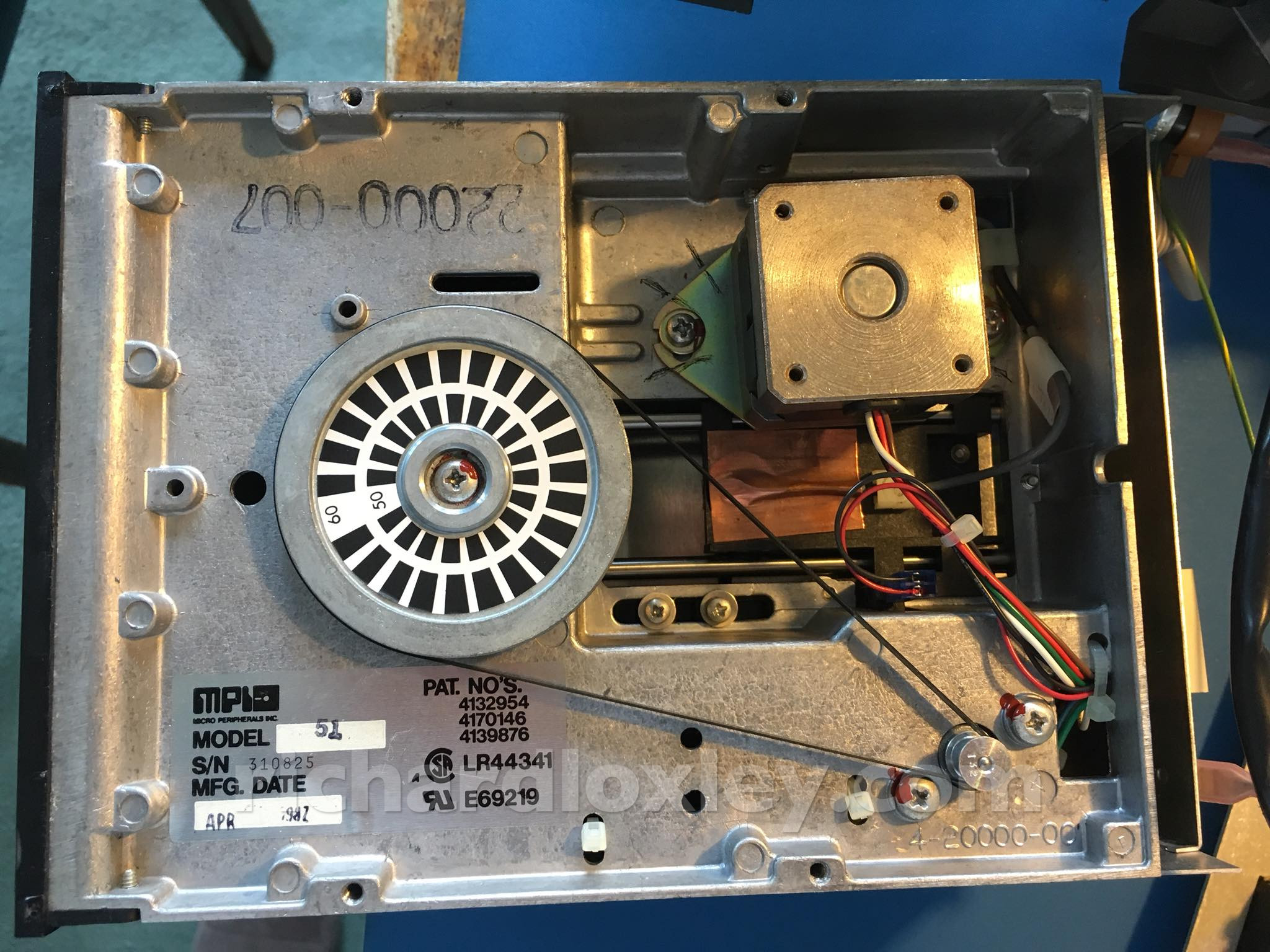
They are designed for mains frequency (50Hz and 60Hz patterns) so you can use an ordinary incandescent lamp or fluorescent tube. Sadly I no longer have either.
I downloaded a strobe light app for my iPhone than will pulse the flash LED. Most only go up to 30Hz but I found one that claimed to go higher. But above about 30Hz it didn’t strobe reliably, so I guess that’s a limitation of the hardware.
Nevertheless I tried it, and at 50Hz the inner strobe pattern was mostly still, possibly advancing very slowly. So I think the rotation speeds are pretty close to what they should be.
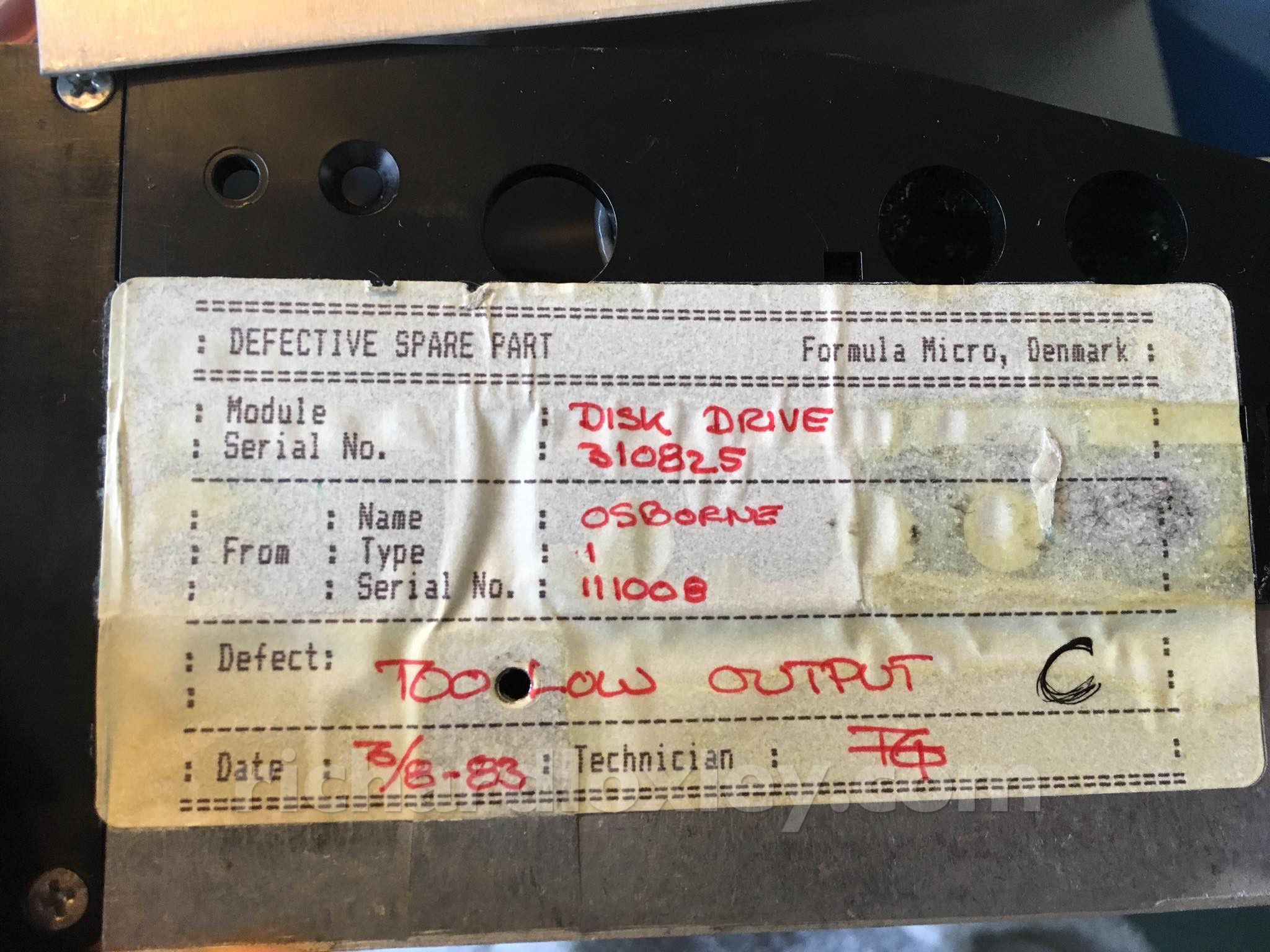
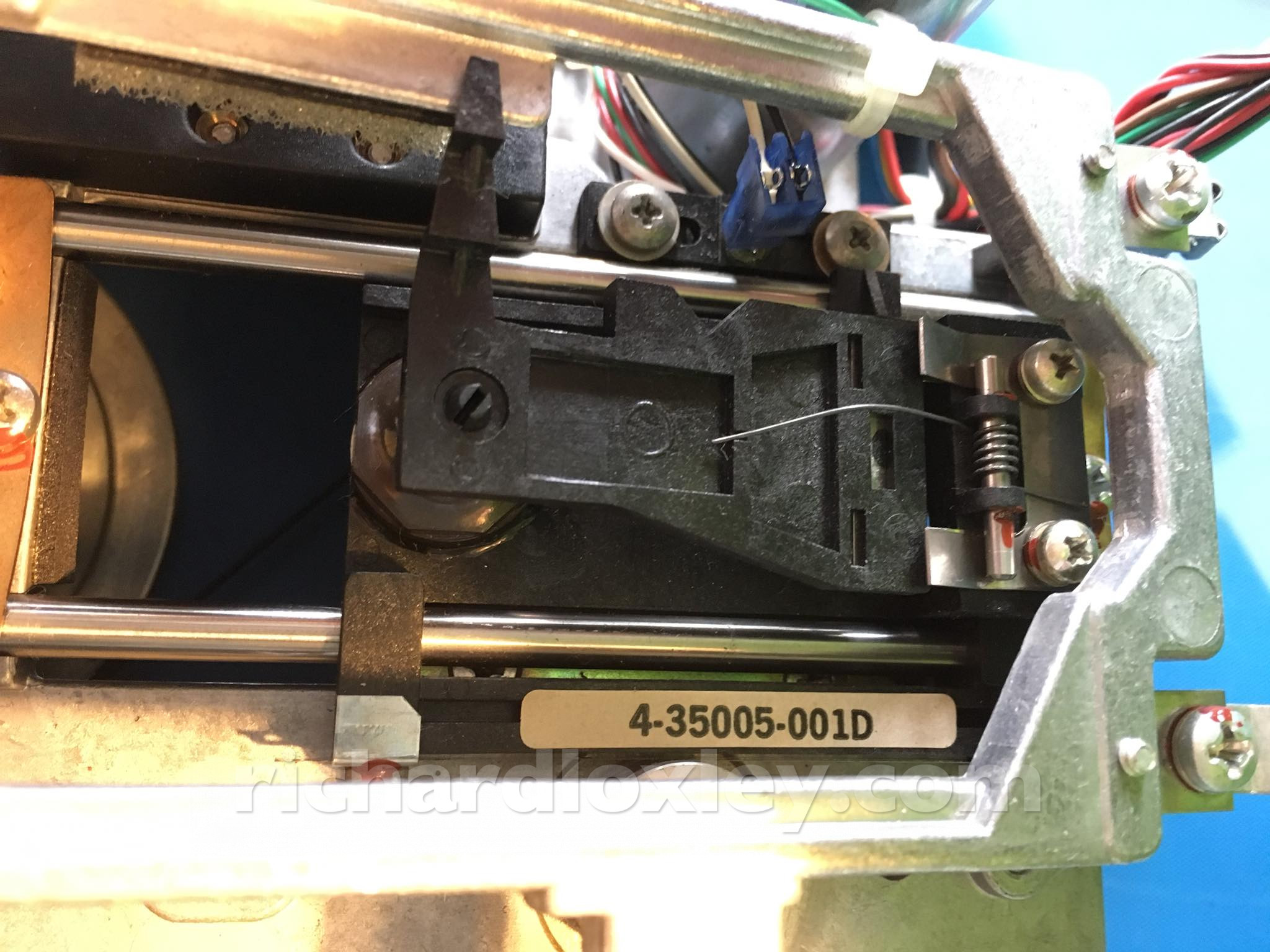
And it has a label on the side. This one has been repaired before!
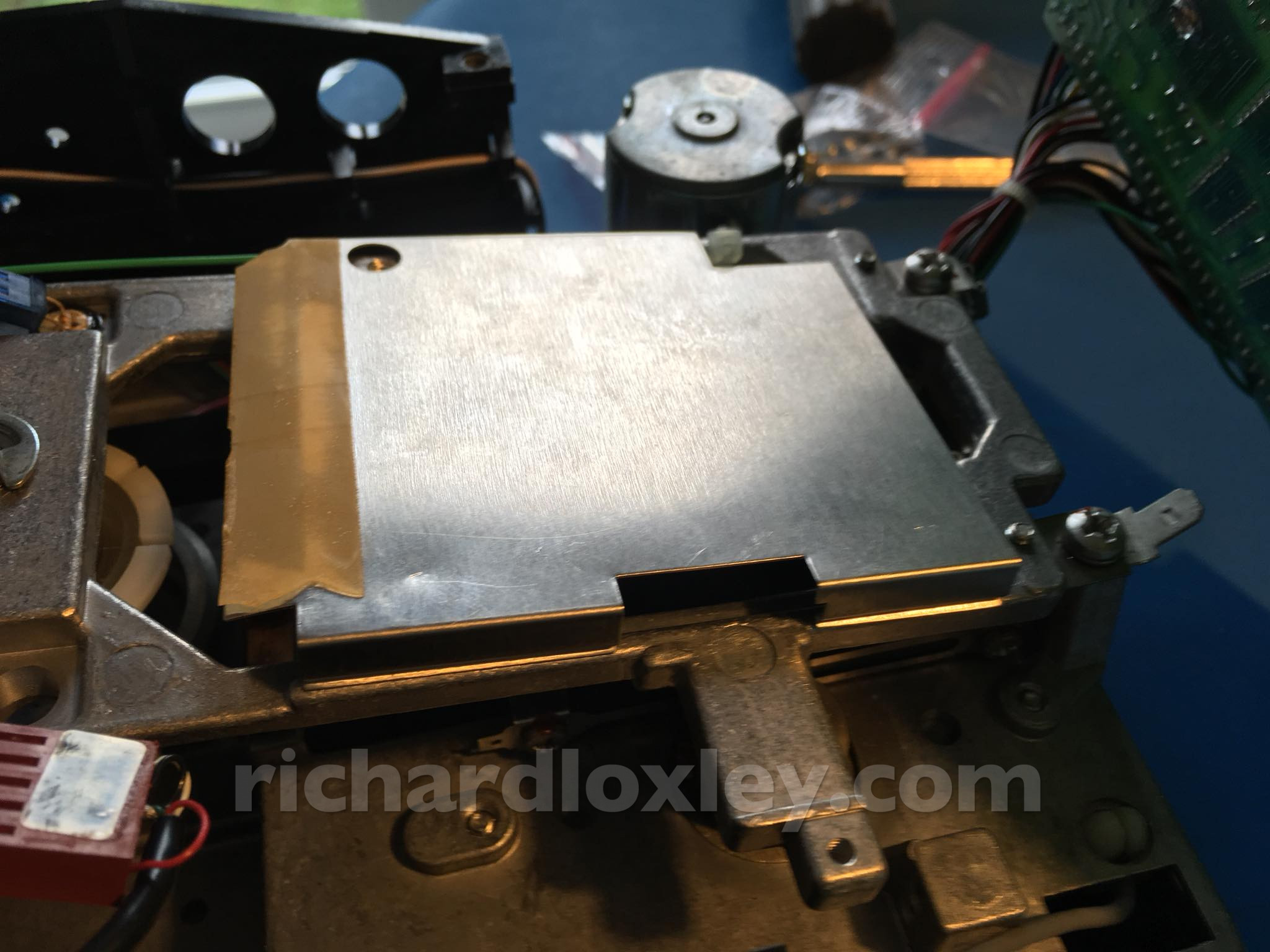
Disk drive out of its case. Now to remove the circuit board to get at the head:
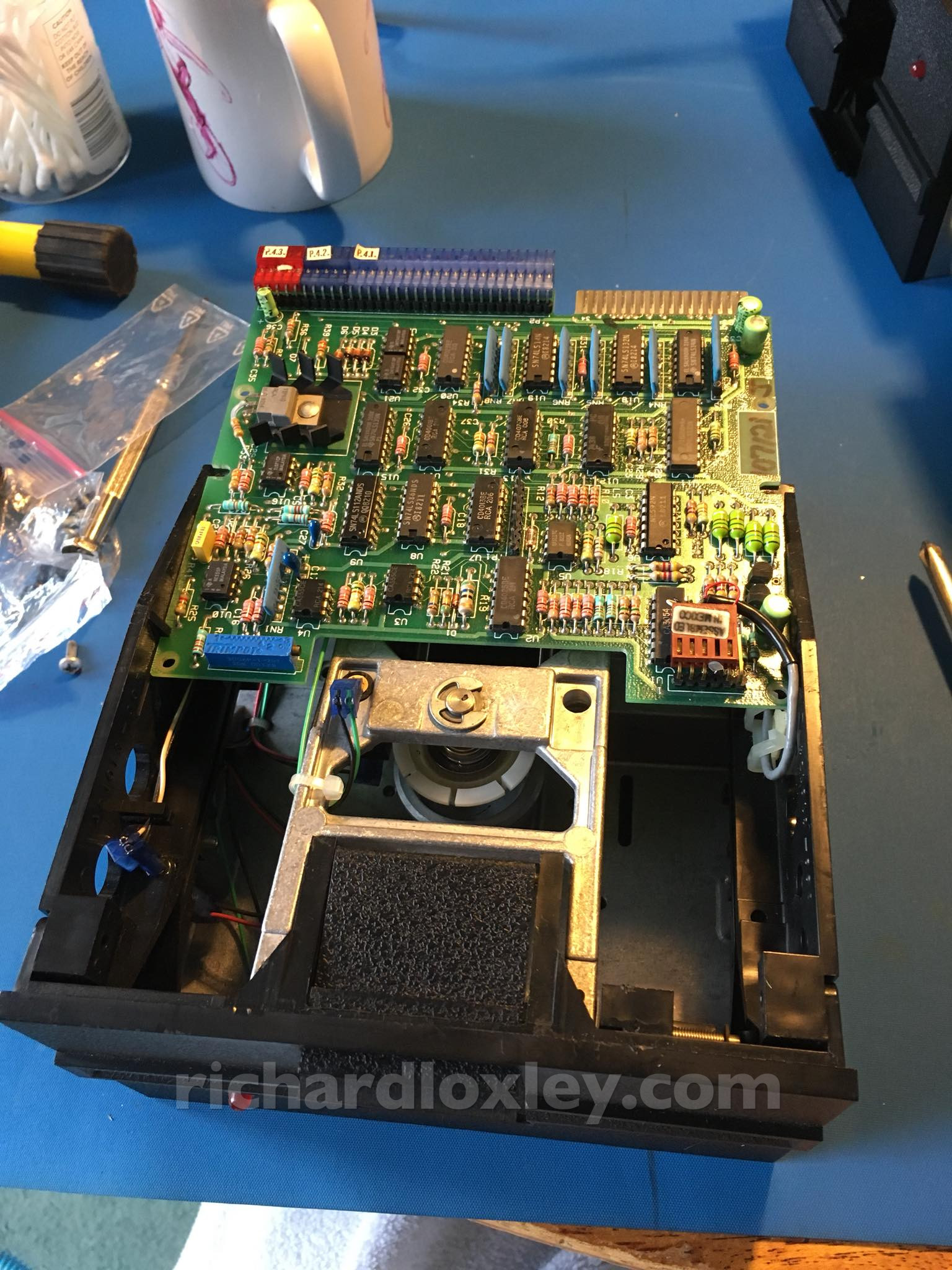
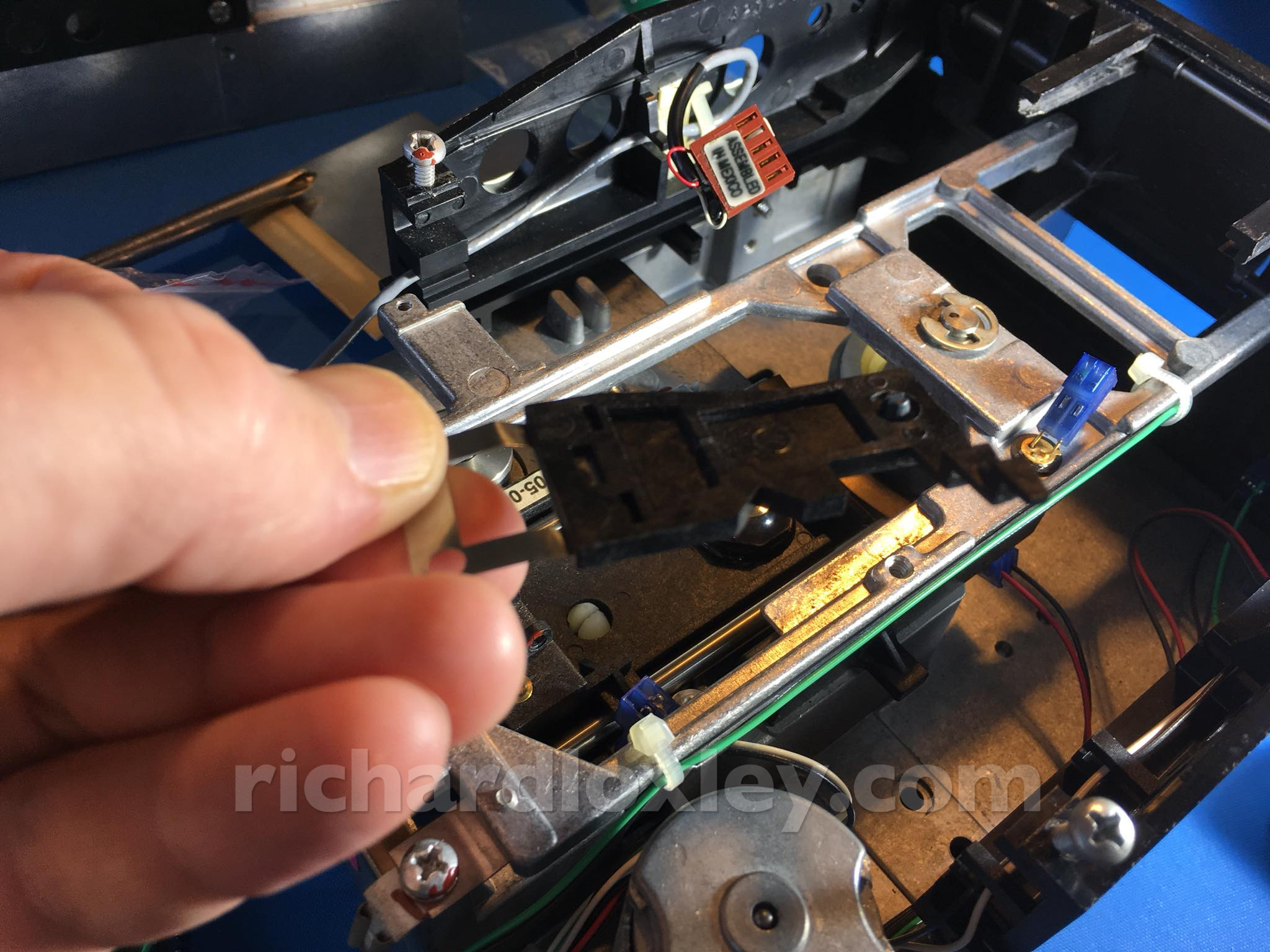
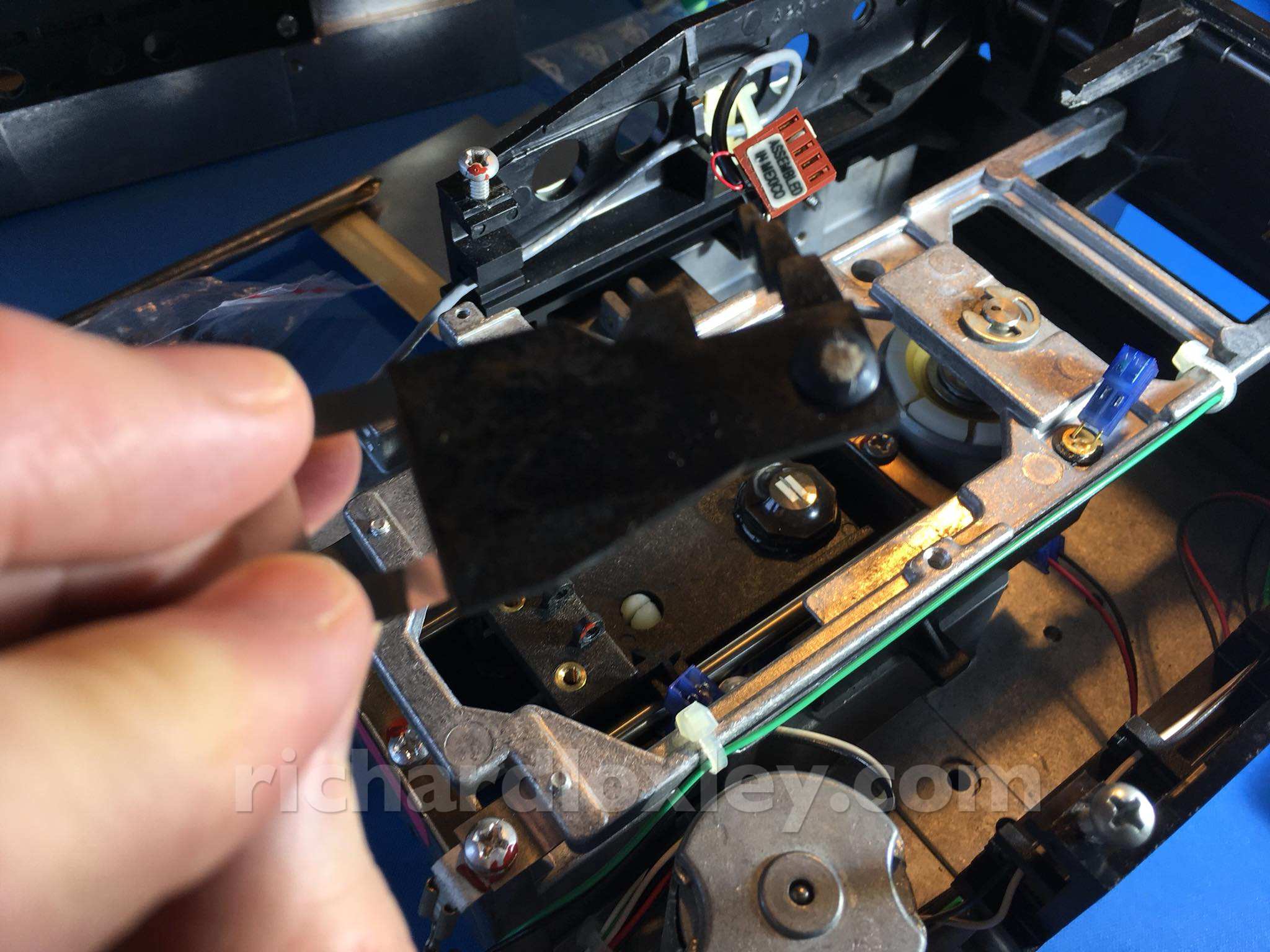
This one has a dust shield over the head:
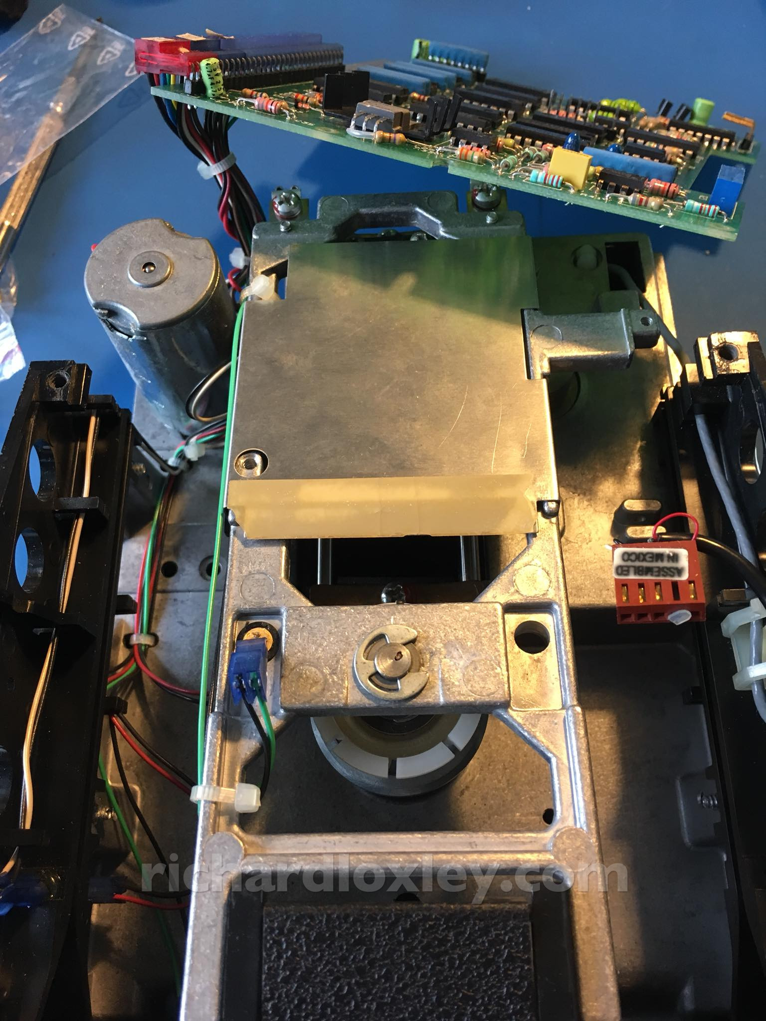
It unclips at the side:
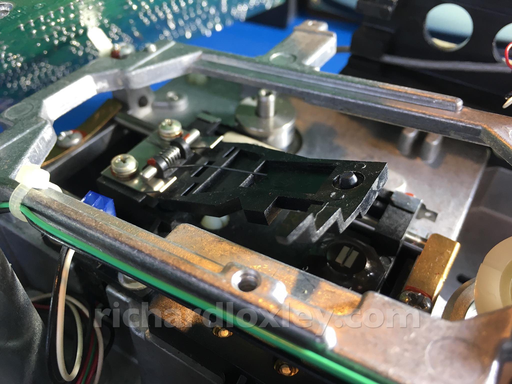
And here’s the spring loaded pressure pad with the head below it:
I lift up the pressure pad to clean the head with alcohol. Seemed damn clean, no residue seemed to come off. I also checked the movement of the head along the rails. Seemed reasonably smooth so I didn’t lubricate them:
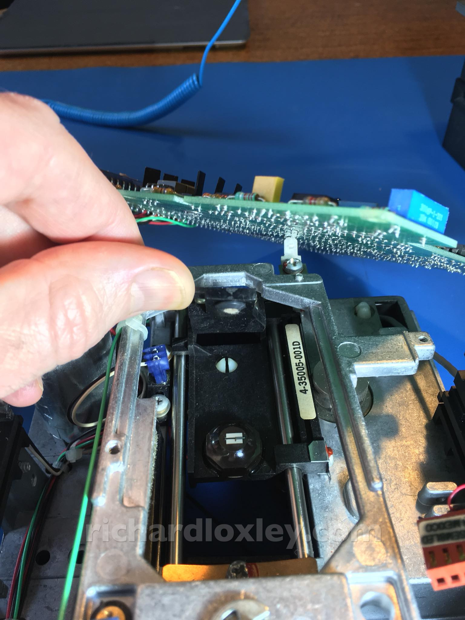
Oops, the pressure pad won’t return to press down on the head. I must have lifted it too high and bent something ![]()
I disassemble the other drive (I wanted to clean it too anyway). But I do it now to compare the two to see what I did wrong.
I disassemble the pressure plate. It seems I bent the metal supports on the left where my fingers are. It took a couple of attempts but I bent it back to give a pressure that seemed consistent with the other drive.
This is the other side of the pressure plate showing the felt pad that presses the disk onto the read/write head:
While I had the alcohol out I cleaned the drive edge connectors too:
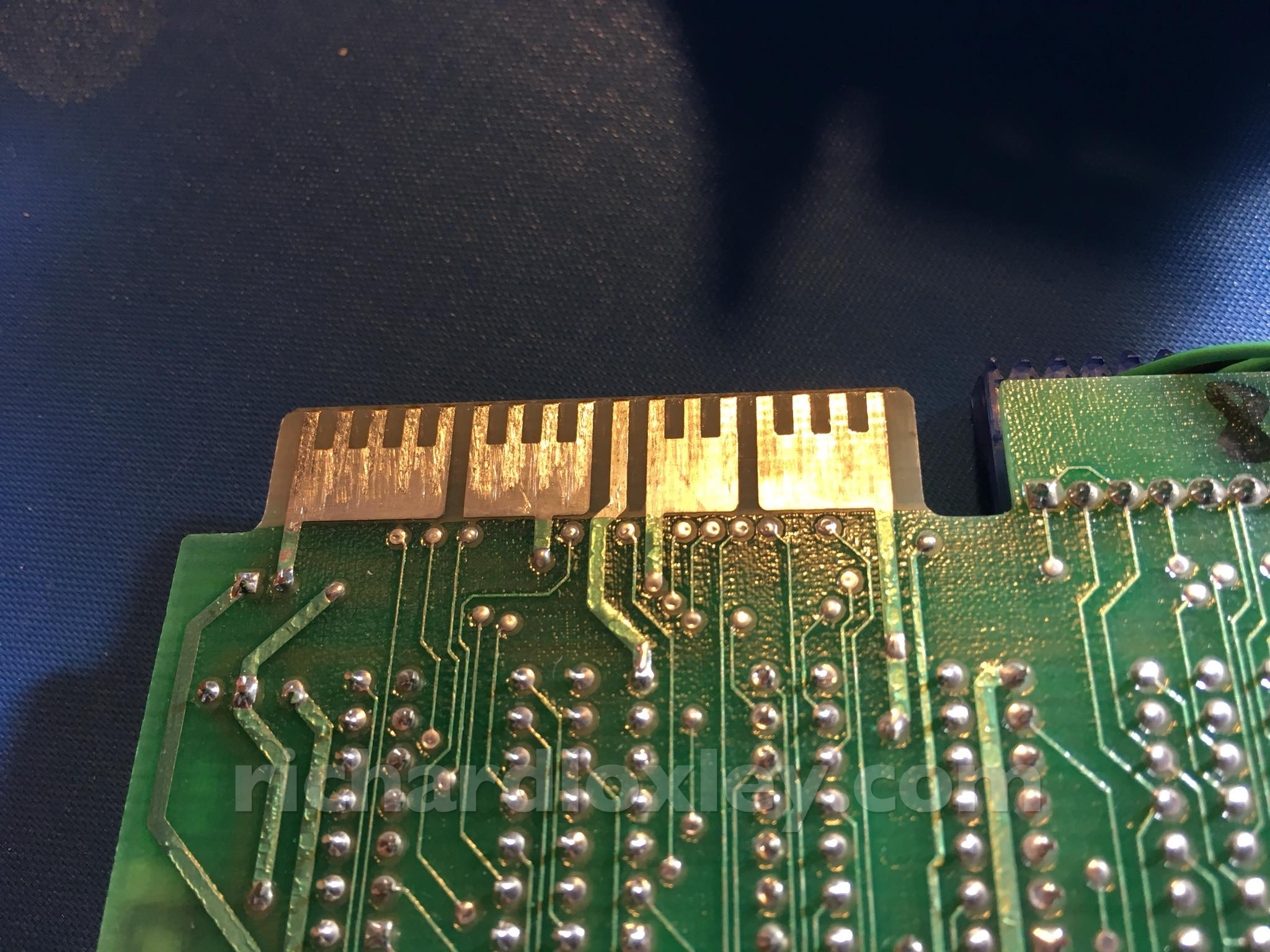
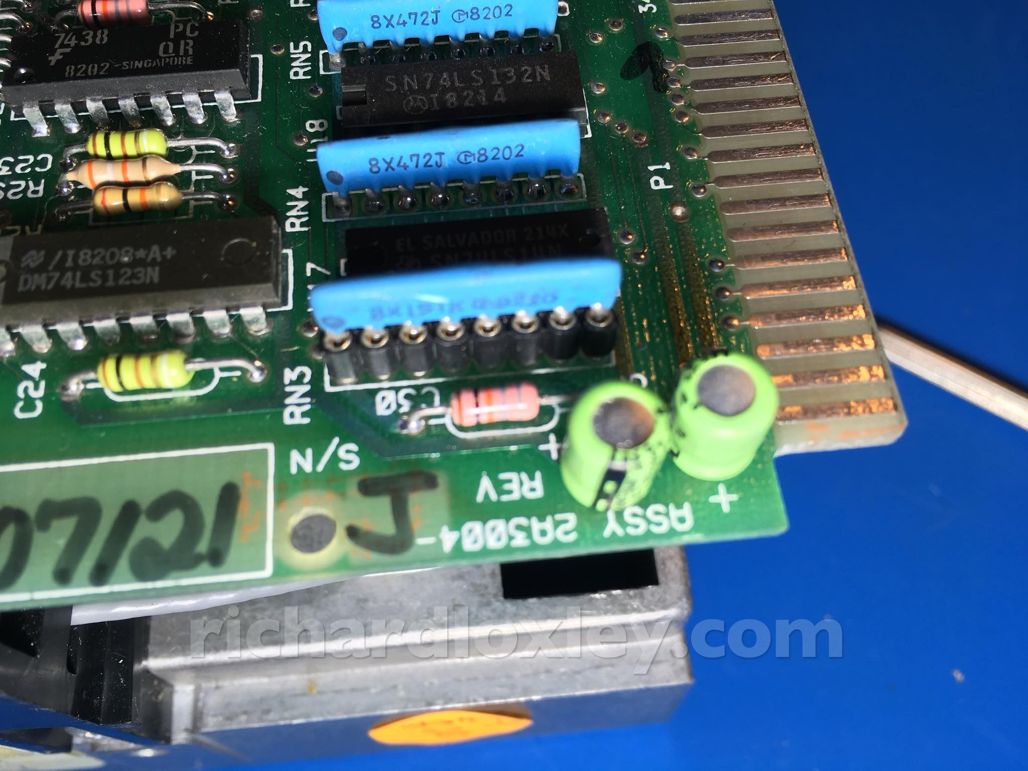
That light blue strip at the bottom is the resistor pack to terminate the cable at the far end from the computer. This is the A drive:
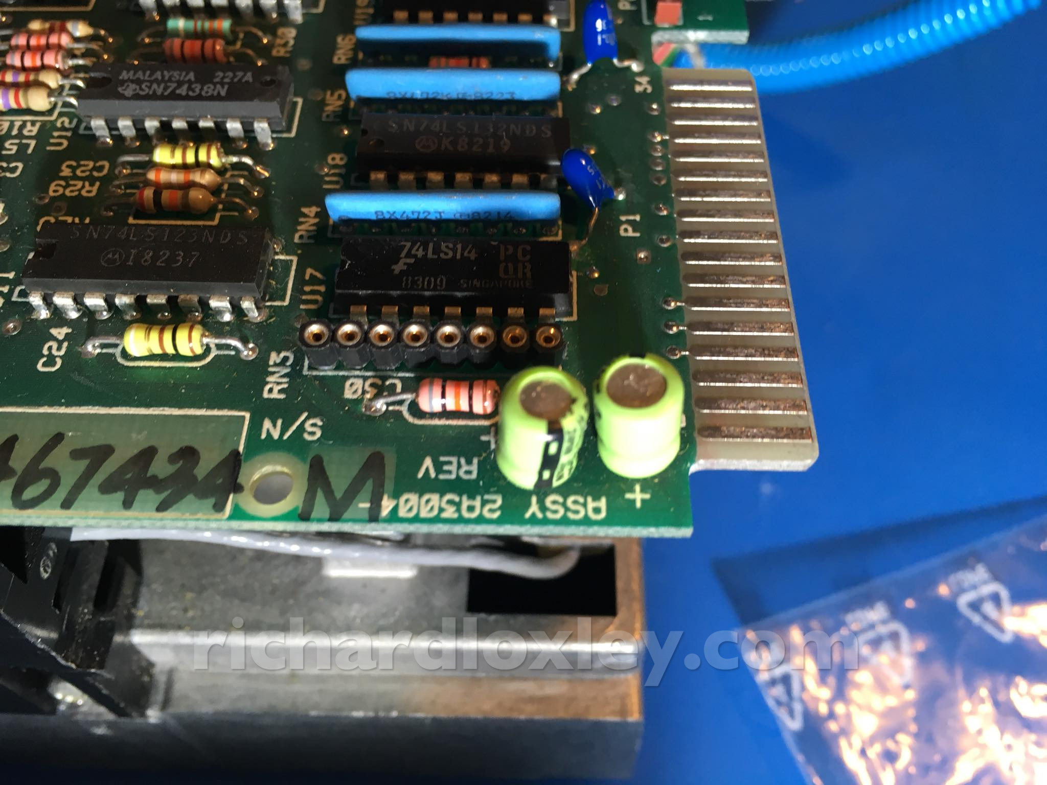
This is the B drive which is in the middle of the cable. Note that there’s no resistor pack on this one:
Powered up. It still works!
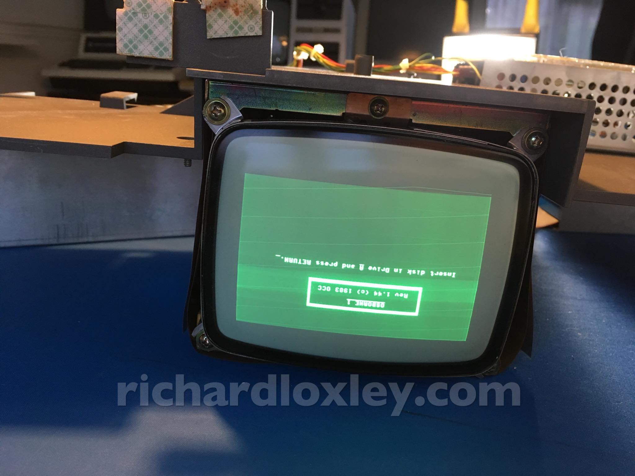
I had a momentary wobble when nothing appeared. I eventually figured out that the cover over the video-out port had fallen off.
This is a strange arrangement where the cover is actually a plug that diverts the video signal to the built-in monitor. If you remove it to access the video-out port it therefore automatically disconnects the built-in monitor!
I left the computer disassembled as the next task would be to try connecting a USB floppy-drive emulator to the motherboard…
The Os is looking in remarkably good condition, considering it’s age :-). This is looking very interesting, but what a wierd port cover!?!