This is part of a series of posts for the Retro Challenge 2018/04. See my index page for the other posts.
In my last post I had successfully got a Gotek/FlashFloppy USB floppy emulator working with my Osborne computer.
For future use, I still wanted to design a way to copy any additional files as and when I needed. I’d already experimented with RS232 serial transfers. I had also wondered about leaving a floppy cable installed somewhere in the machine so I could attach a USB floppy emulator easily when I needed to, but it was in no way obvious how to do that without leaving the aesthetics of the machine a bit ‘messy’.
Today’s job was to solve that dilemma.
I discovered that if I removed the top of the case from the Gotek drive, it would fit quite nicely in one of the floppy disk storage slots on the Osborne:
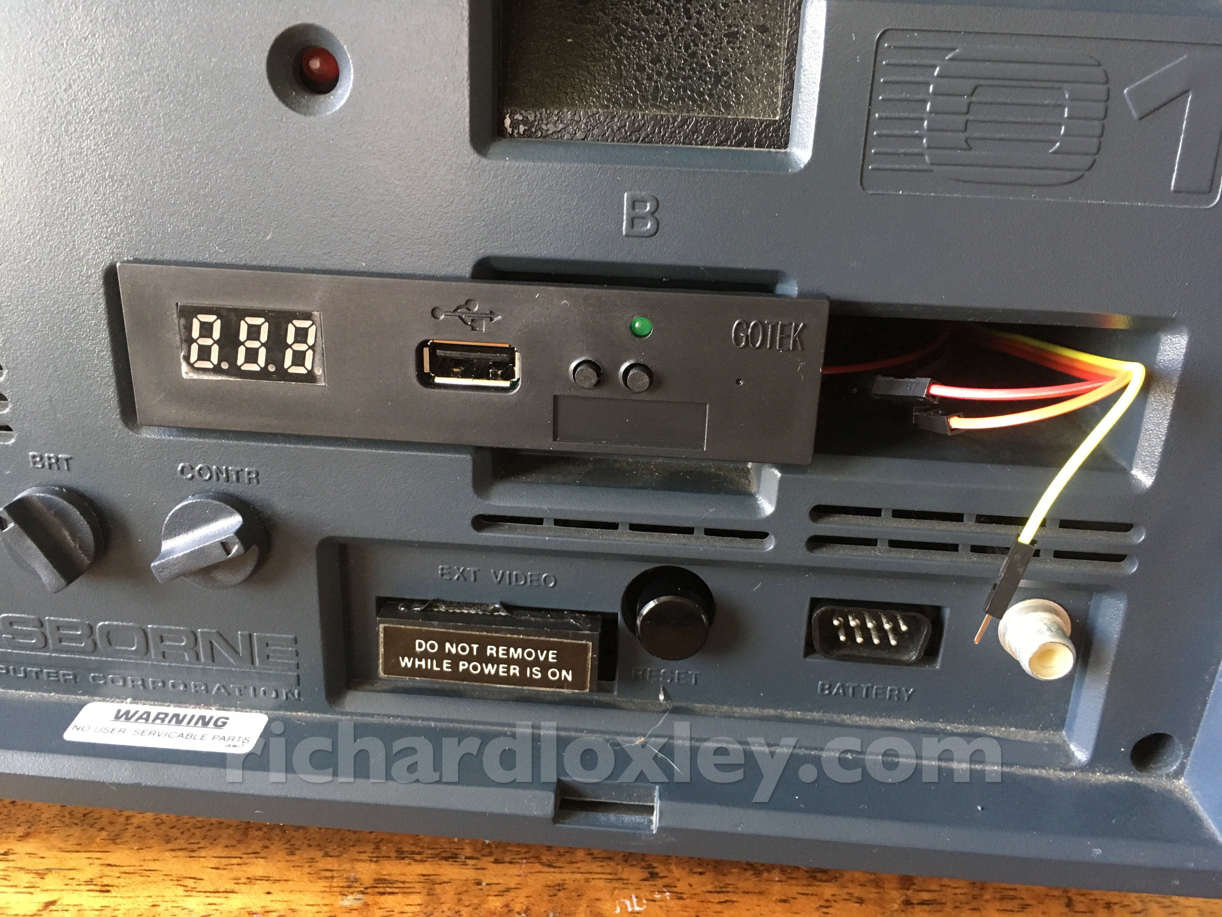
I quite liked that idea, as it would let me keep a USB drive emulator in the Osborne case where it was easily accessible, but without needing to make any permanent changes to the Osborne.
I’m sometimes willing to make changes to retro equipment, but only to very common machines. For something as rare as the Osborne any modifications had to be easily reversible. Ideally they shouldn’t change the aesthetic too much either. I think this solution might fit the bill.
The only problem was how to route cables to the floppy. A typical 34 pin floppy cable is very wide.
I measured one, and I could just get one through the hole of the “Ext Video” port (where it says “DO NOT REMOVE WHILE POWER IS ON” in the above photo). But then a light grey cable would snake its way up the outside of the machine. I also eyed-up the ventilation slot just beneath the Gotek, as it’s the perfect width, and the cable would go up nicely through the indents designed to allow your fingers to grip the stored floppy disks. But that would mean permanently removing the vertical bits of that grill, which I don’t want to do.
On the left side of the machine I could get a cable out of the IEEE 488 port, but then the cable would go diagonally up to the left storage pocket. The RS232 port is more central, but it would be a tight fit to get the floppy cable alongside the socket, and might stop me using the RS232 (which I will probably still want to use).
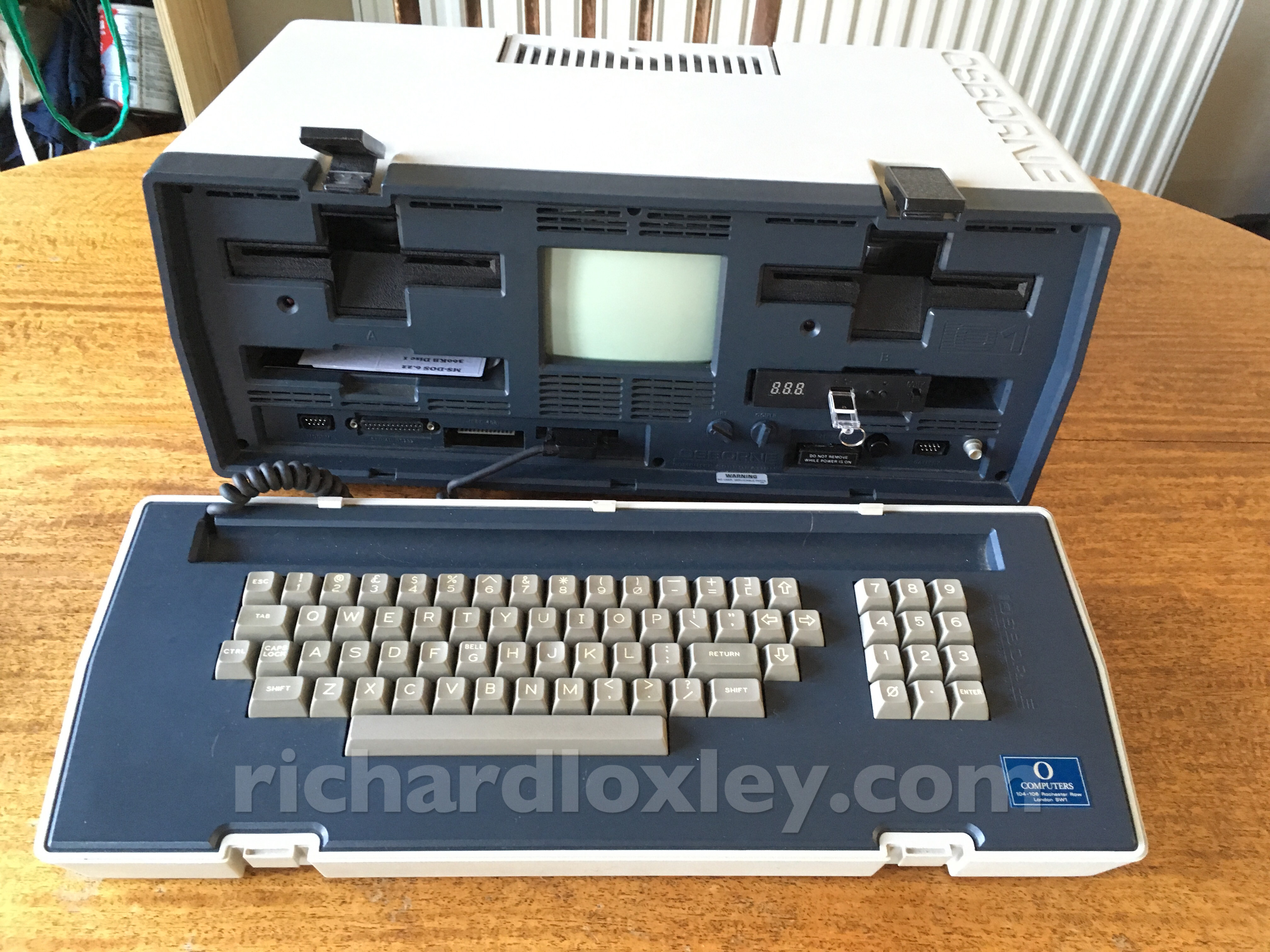
Either way, I don’t really want to use the left pocket, as it’s very hard to fold up the keyboard unless you tuck the keyboard cable in that slot!
So let’s work on the idea of putting the Gotek in the right pocket, and have it emulate a B drive. Ideally we’ll have a way of switching between the physical B drive and the emulated B drive.
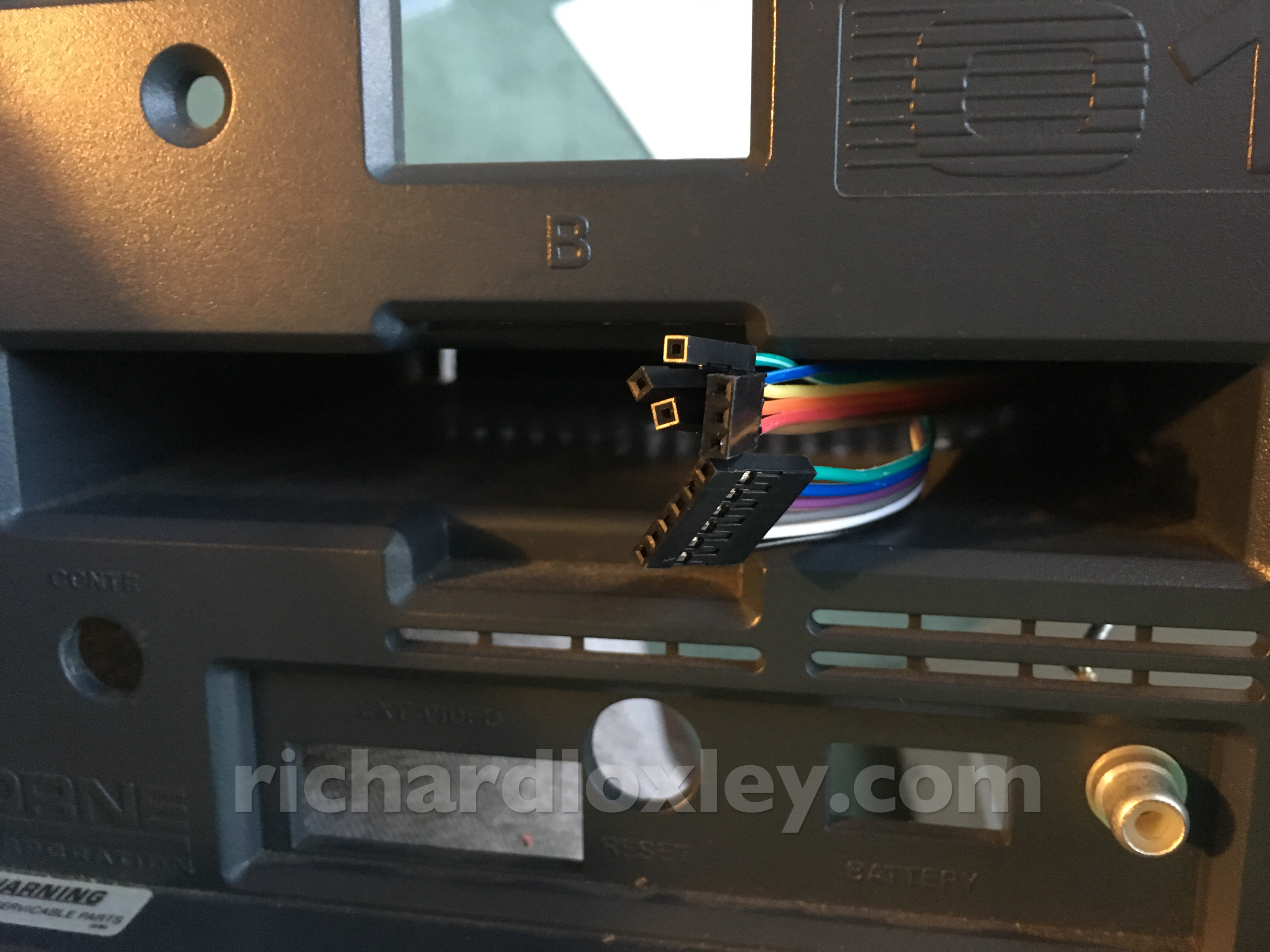
So next I investigate the ventilation slots at the back of the storage pockets:
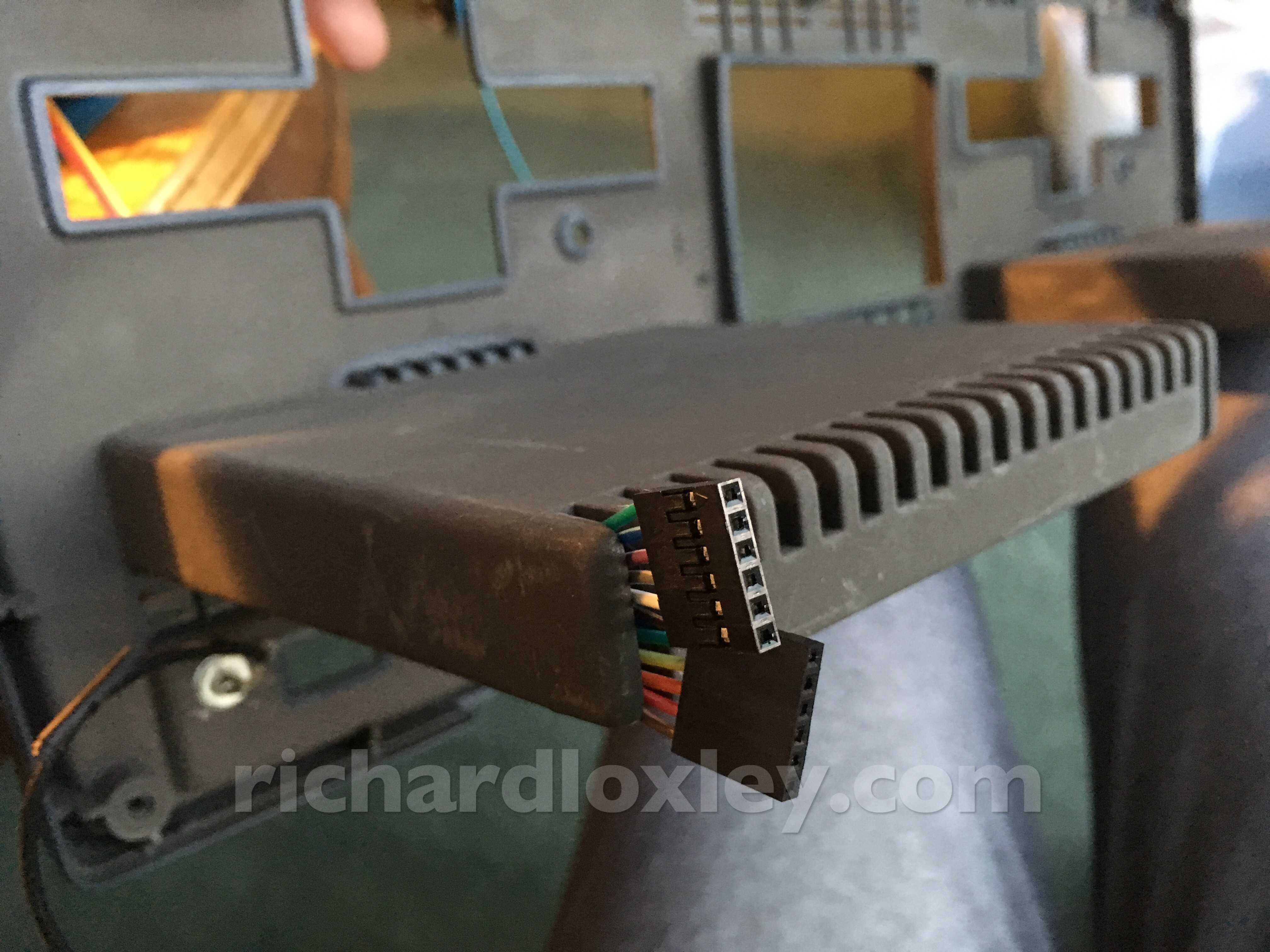
They wouldn’t fit a floppy connector. A floppy cable would probably fit through if I doubled it up – but then I’d have to install plugs either end after feeding it through, making the cable fairly permanent (without cutting it). Not ideal.
But I could get 6-pin Dupont connectors through the slots. Hmm. How many signal lines do I actually need? I did an audit:
- pin 8: index
- pin 12: drive select B
- pin 18: direction
- pin 20: step
- pin 22: write data
- pin 24: write gate
- pin 26: track 0
- pin 28: write protect
- pin 30: read data
- ground
- 5V (to power the emulator) – which the Osborne already provides on the floppy cable
That’s just 11 pins :-) If I want to switch between the physical and emulated drives, I’ll need an extra line connected to a switch to send the drive select signal back to the physical drive. That’s a nice round dozen – or two 6 pin cables that will happily fit through the slots!
So I design this rather convoluted wiring diagram:
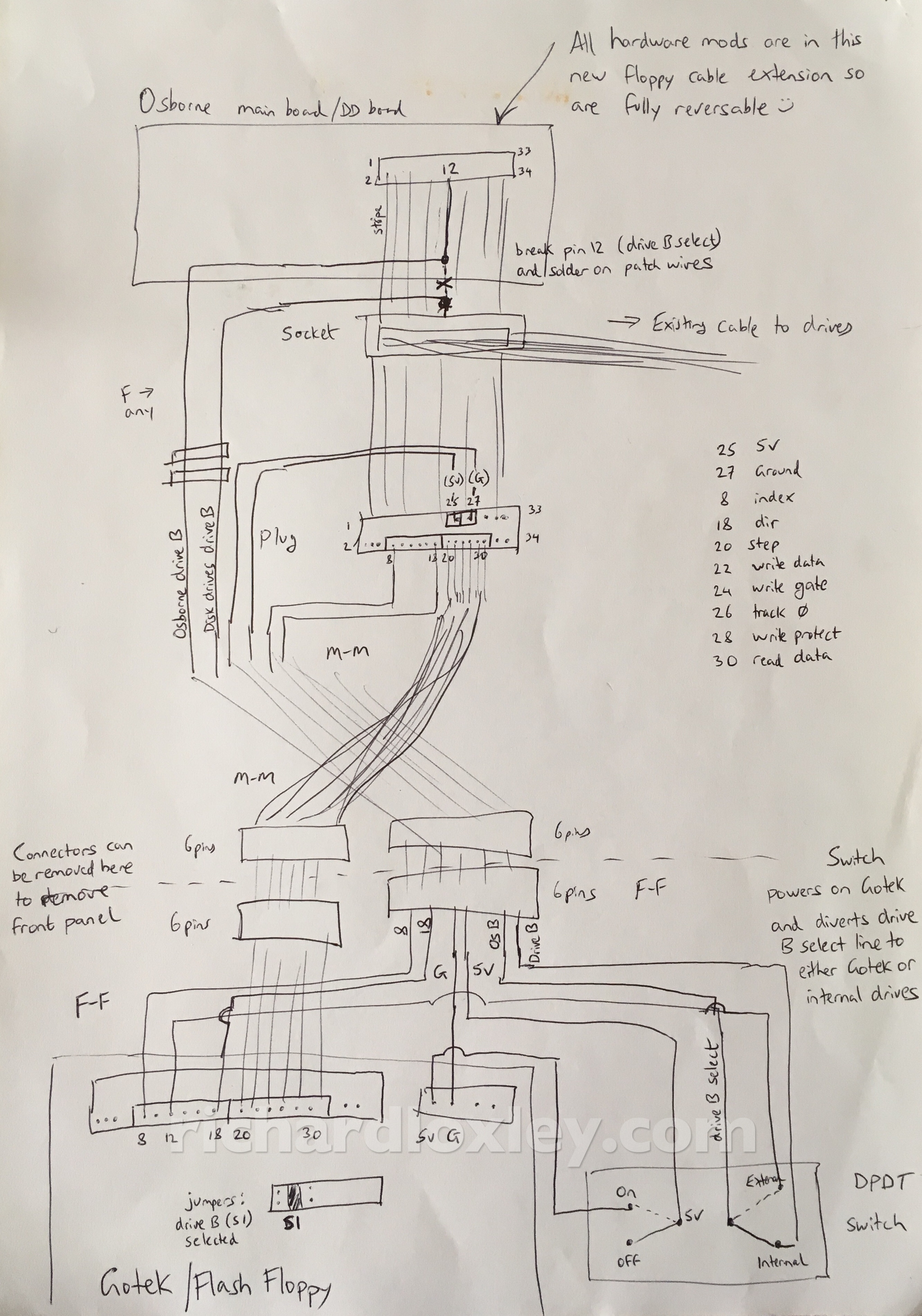
The idea is I have a 34 pin floppy extension cable inside the machine, to intercept the existing floppy cable without cutting it. Then I use Dupont ribbon cables (from a floppy plug) to take the signals I need to the front of the machine. Then further Dupont ribbon cables take the signals into the floppy storage pocket to the Gotek drive.
Everything is removable, and in modular sections for easy disassembly of the machine in the future.
The DPDT switch will allow me to switch the Gotek on and off, and when it is on the drive select signal will be routed to the Gotek, and when off it will be directed to the physical B drive.
So I order some appropriate DPDT switches from eBay, and start work on the cabling…
I cut the drive B select line in the extension cable just after it leaves the motherboard as it needs to be completely diverted:
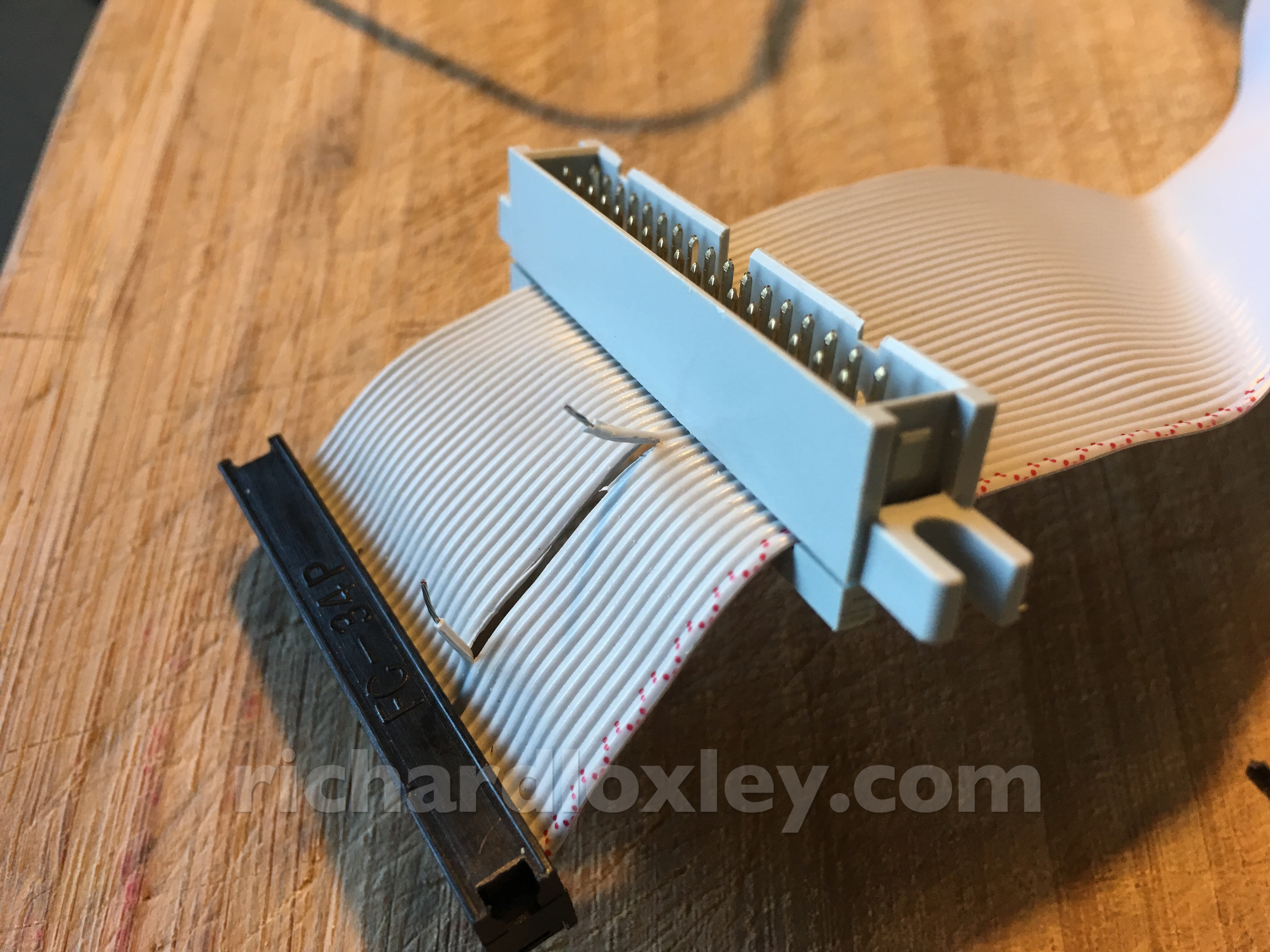
And feed it on to a separate ribbon cable:
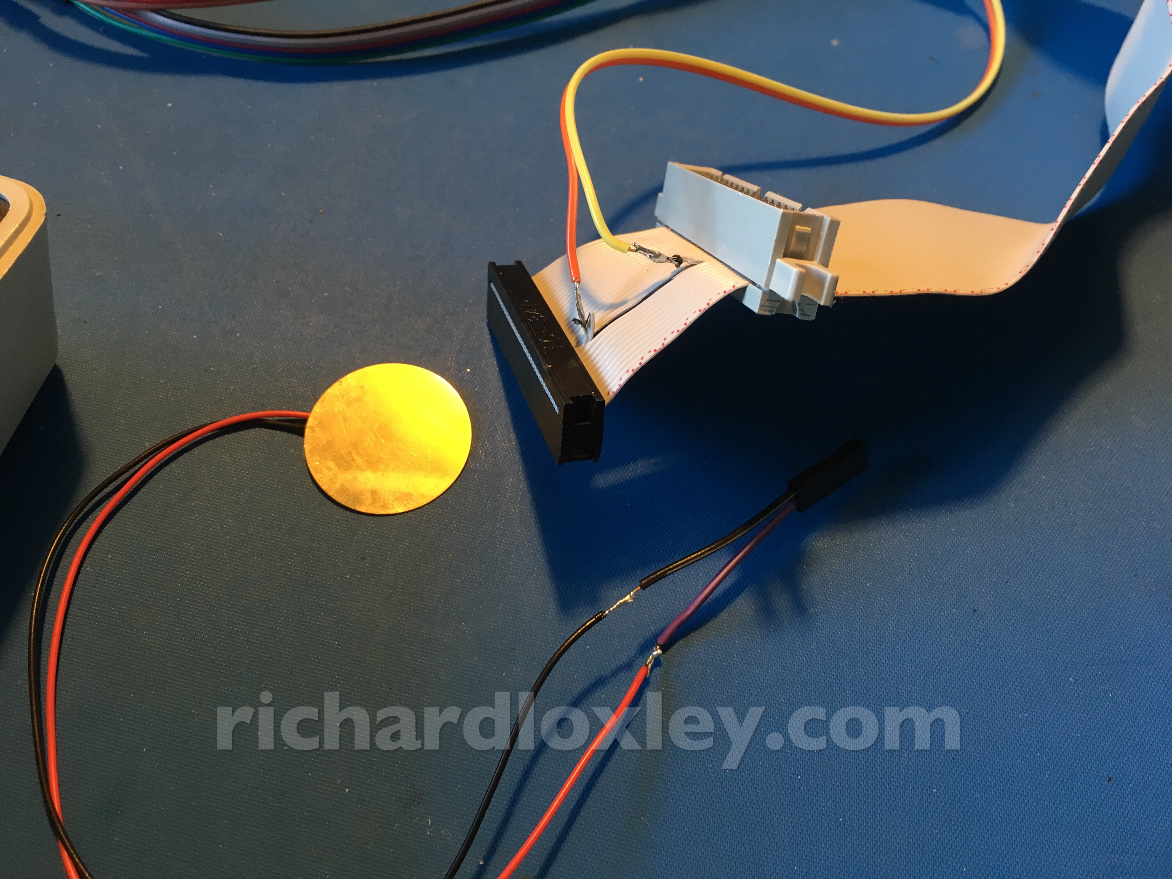
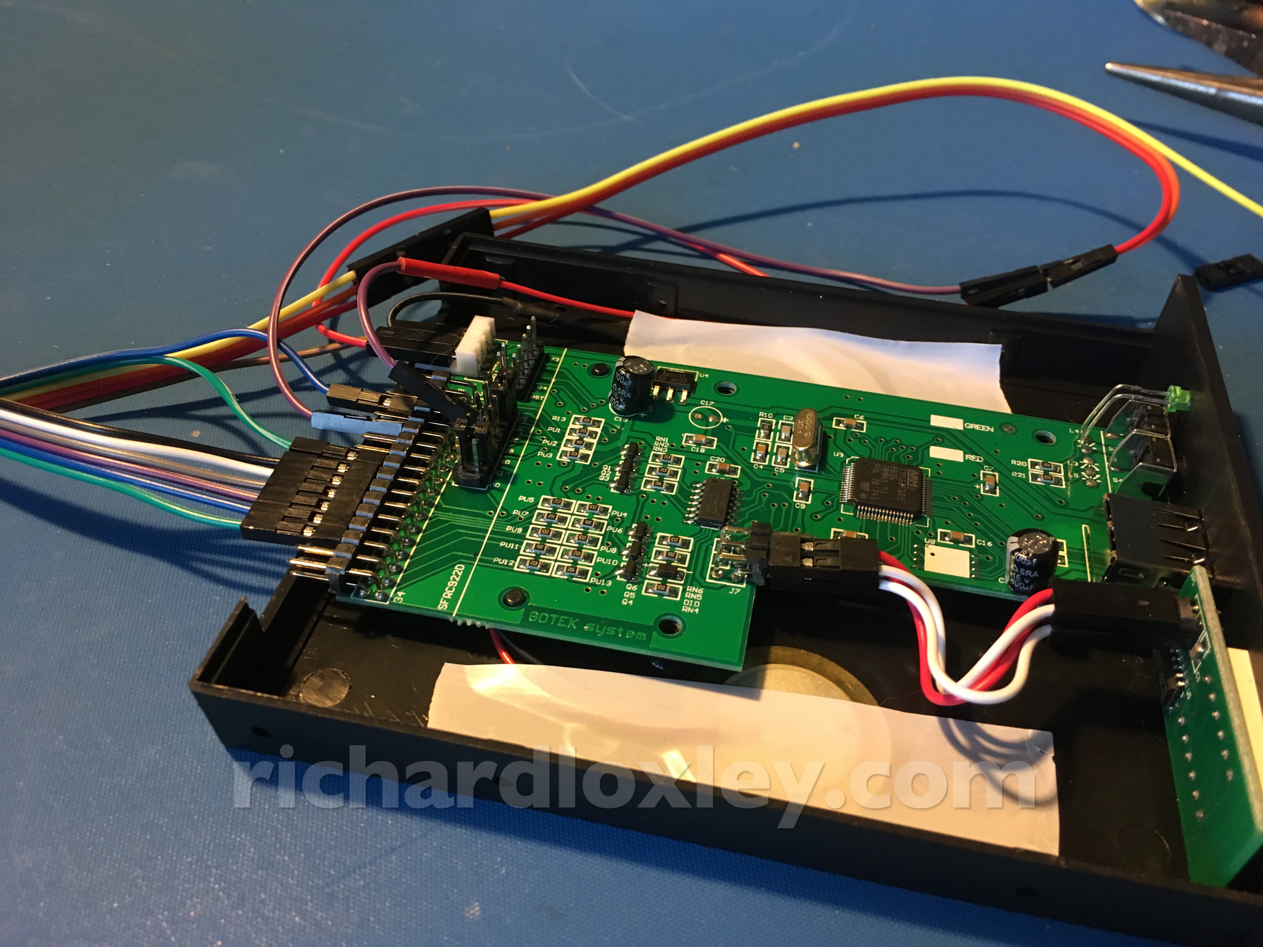
I take the other signals from a socket on the extension cable. Connectors colour-coded for future convenience!
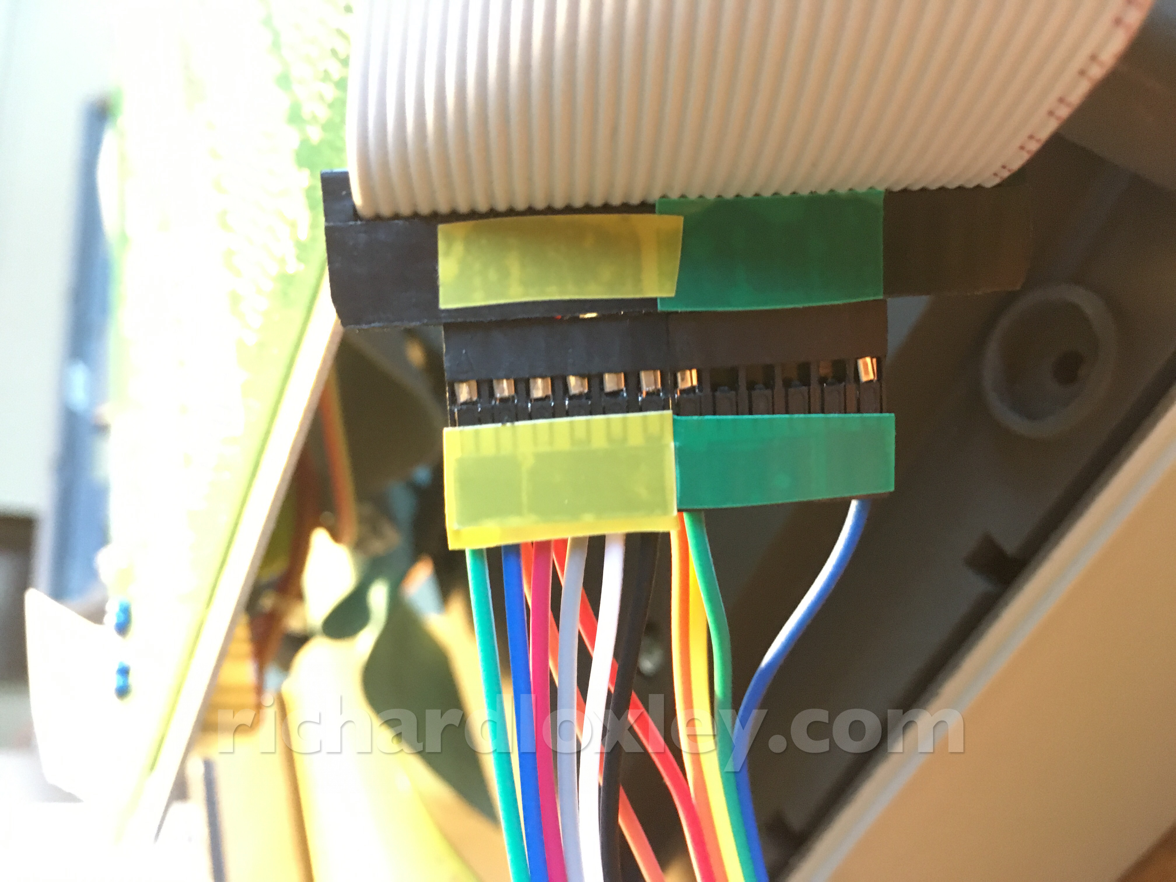
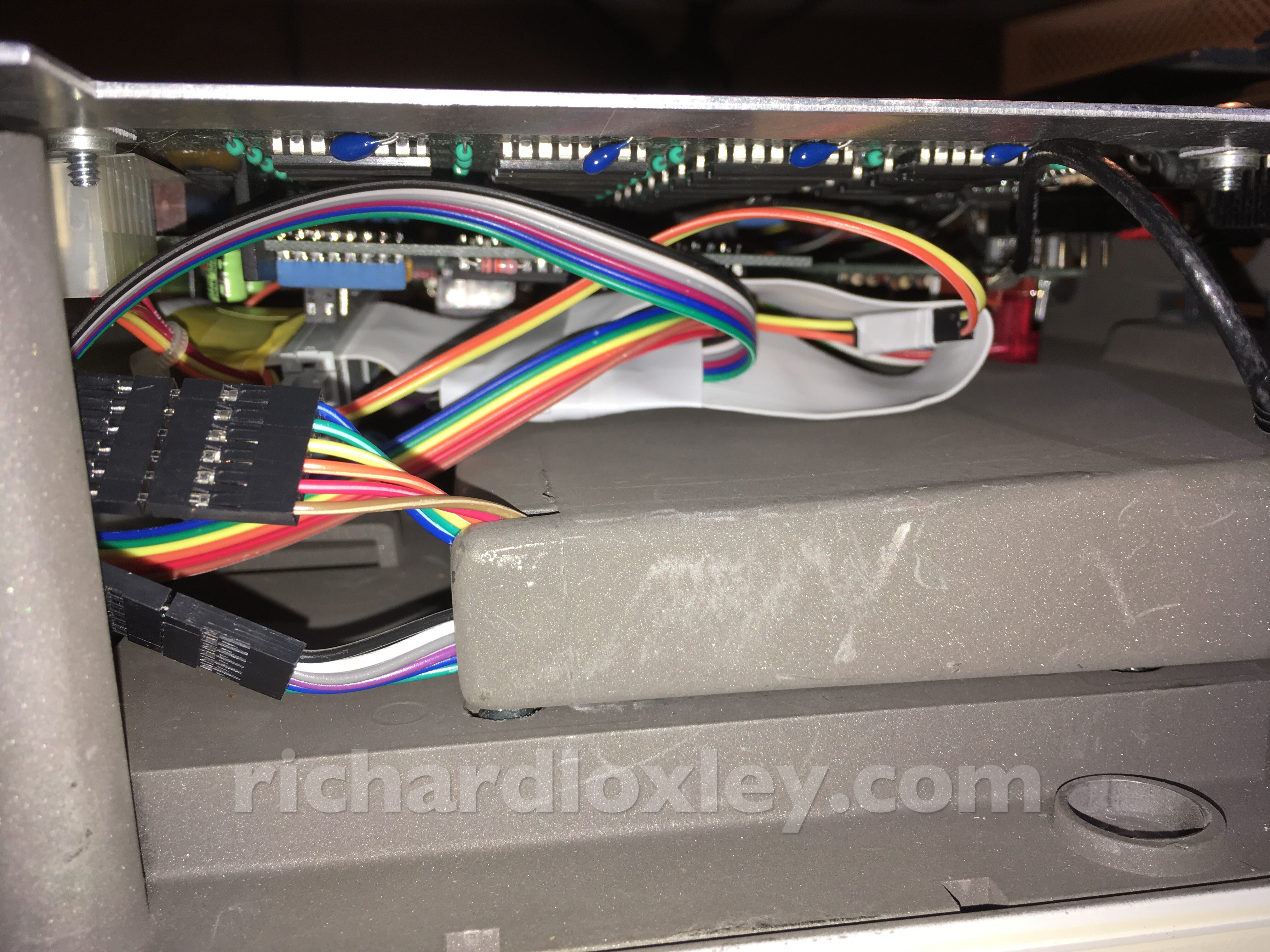
And everything gets fed out through the hidden ventilation slots:
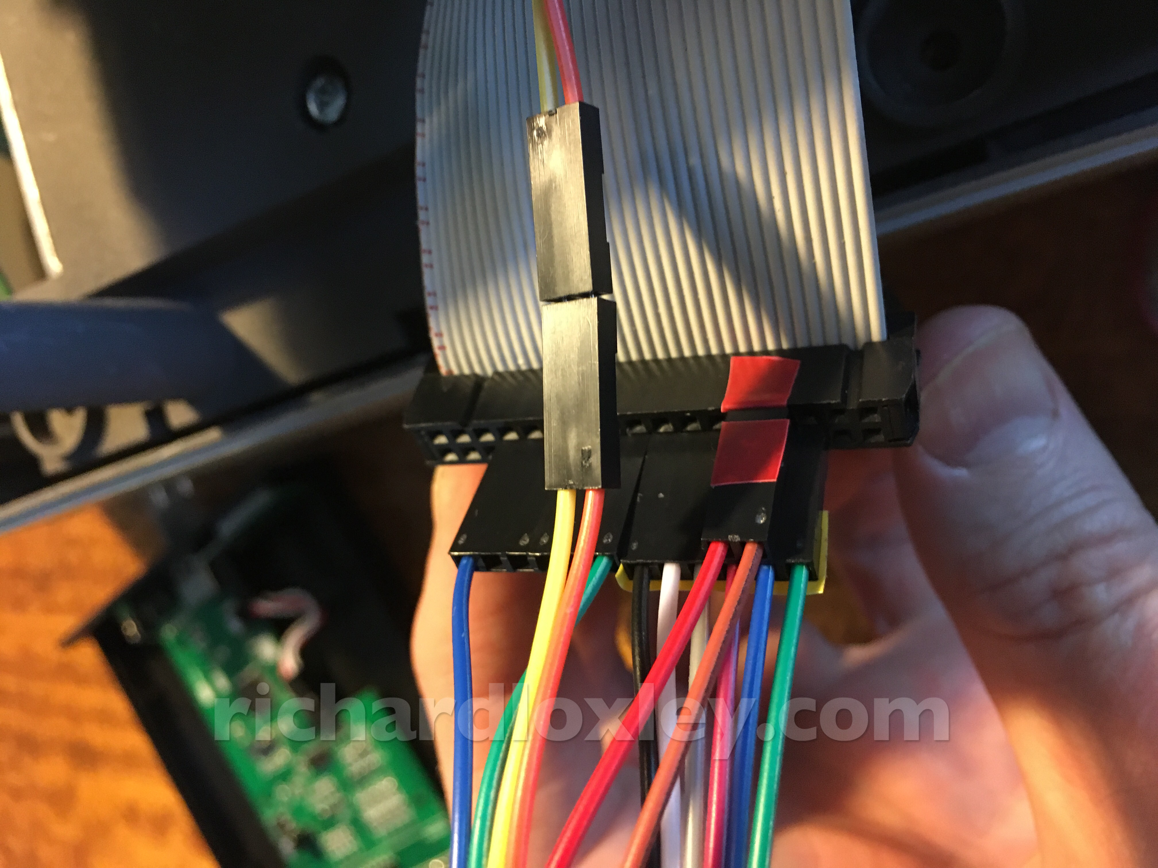
The Gotek/FlashFloppy drive seems to still work with the cut-down cables:
It was a tight fit getting the computer back together with all the extra cables. I had to do it in the ‘wrong’ order – putting the front on first (loosely) before the bottom, so I could arrange the cables appropriately:
But it seems to work. (These extra jumper cables out the front are to simulate the switch that hasn’t arrived yet!)
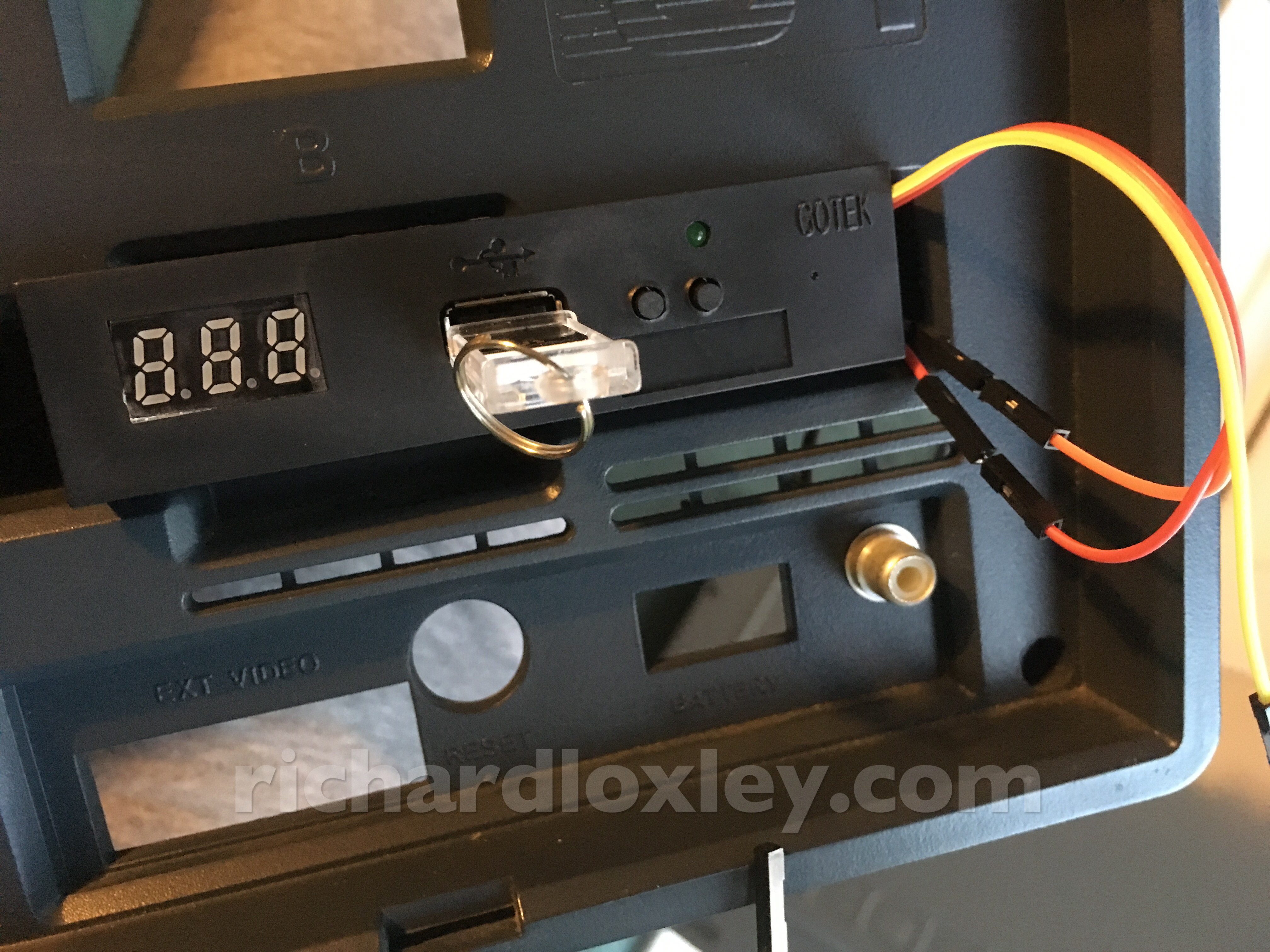
This is looking like it’s going to work!
Now to wait for the next components to arrive.