This is part of a series for the Retro Challenge 2019/3. Visit the index page for all the posts.
So March is already turning out to be busier than I expected!
I have a lot of work on at the moment, so the original plan was to just spend each weekend on the Retro Challenge. But life gets in the way, and by 6pm on Sunday I haven’t yet started!
Still, let’s try to get something achieved anyway.
The idea this year is to resume some hardware debugging on my retro computer collection. A few repairs got stalled as I lacked the diagnostic tools to get any further.
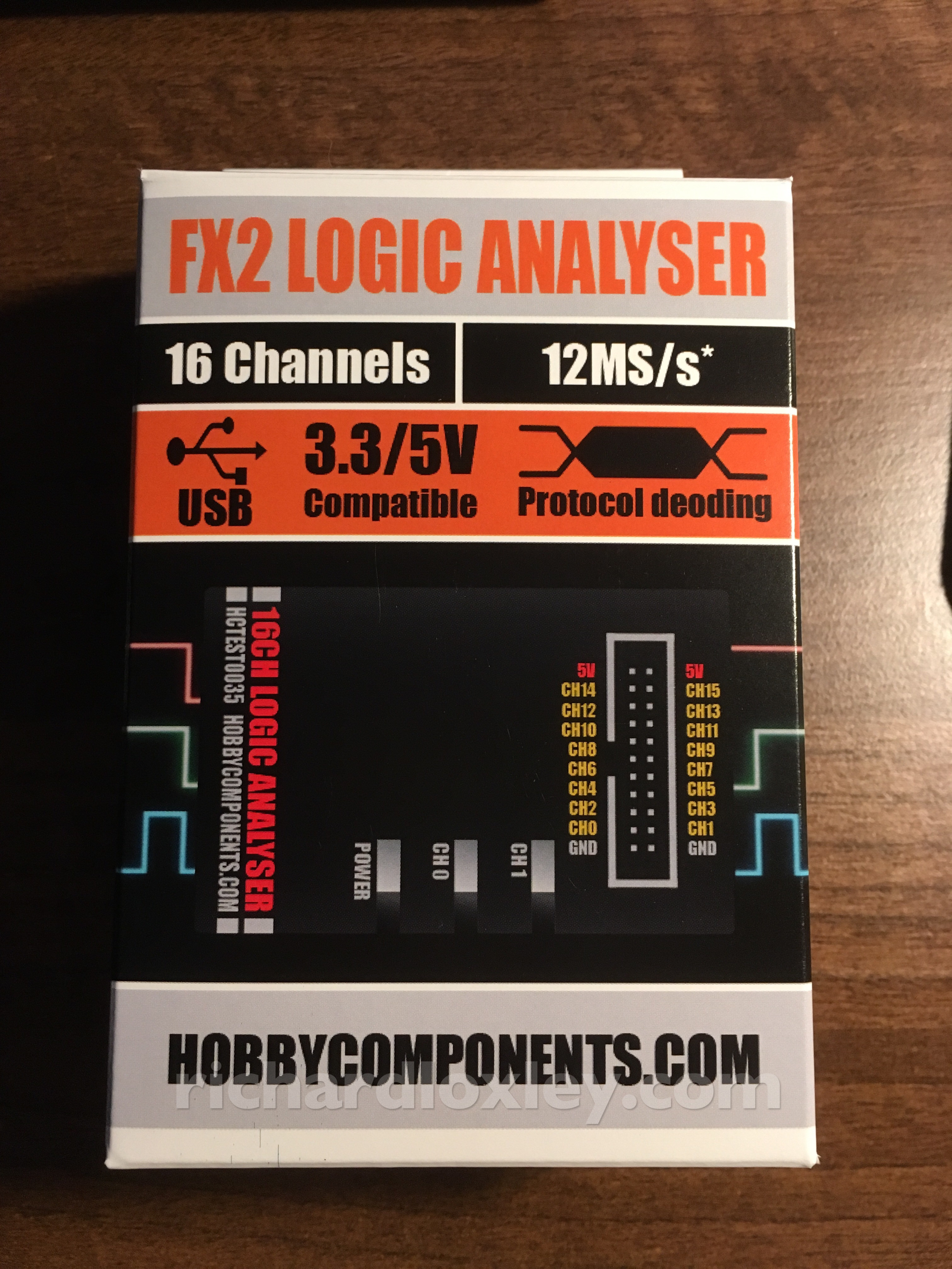
In the last year I discovered the existence of very cheap USB logic analysers. For £26.46 (including postage) I got this 16 channel logic analyser from Hobby Components:
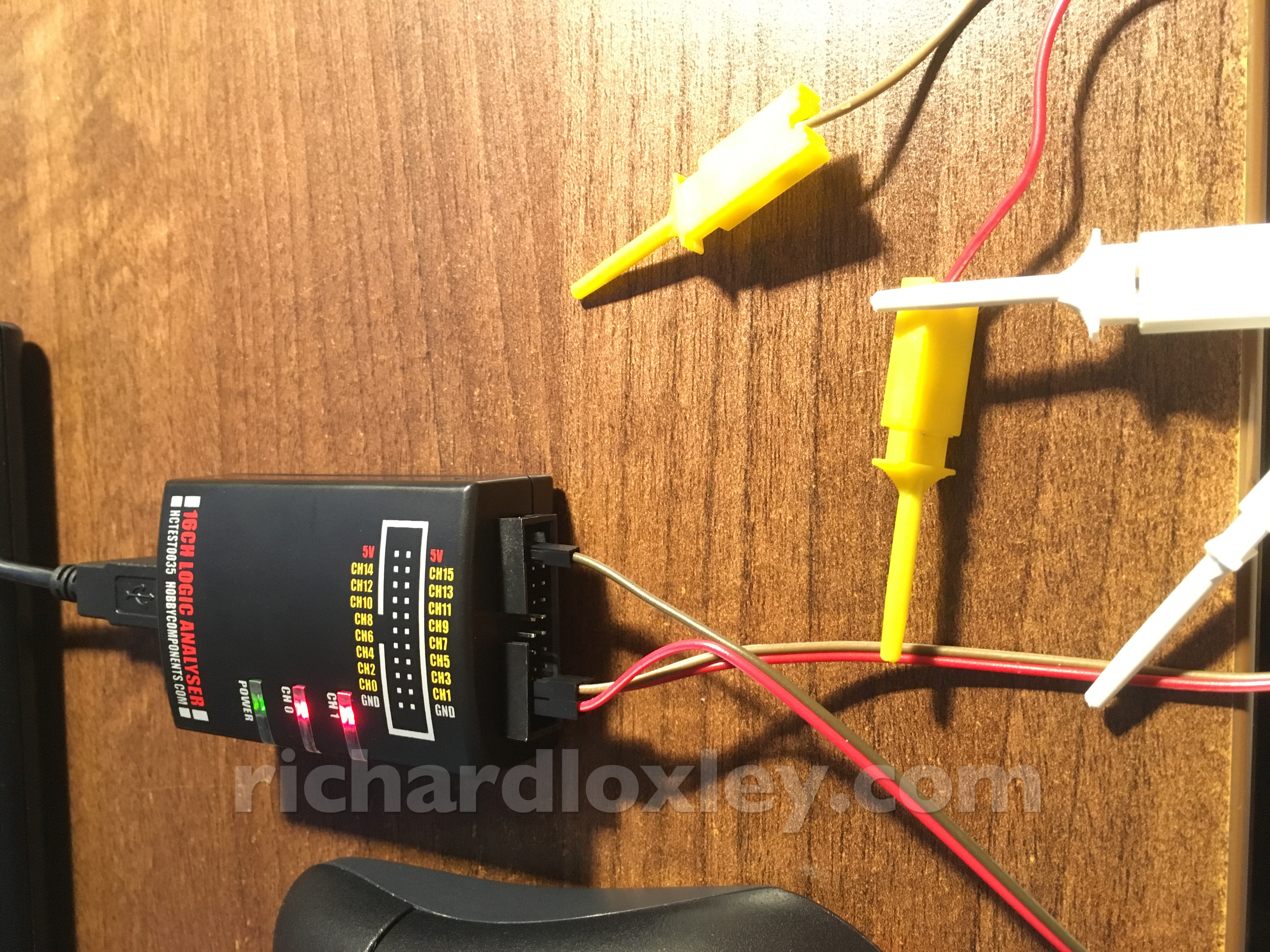
It comes with a set of test hook clips (four shown here).
It is compatible with the sigrok open-source software. Thankfully that is still compatible with Windows XP, which is what powers my old Asus EeePC netbook. That’s the only device I have that’s portable enough to get near the electronics I’m likely to want to analyse!
Installation of the software was pretty smooth. The instructions warn that I might need to install some Windows run-time components. Last month I had a right headache installing some other software on the netbook, and had to install loads of different Windows packages to get it to work. Presumably I’ve now already got all the prerequisites on there!
The sigrok PulseView GUI software didn’t immediately detect the USB logic analyser. Hobby Components gave some bare bones but useful instructions to install the Zadig driver shipped with the full PulseView installer. After installing the Zadig driver I still needed to let the Windows New Hardware wizard do its thing before it stopped nagging me (and it also seemed that was necessary for PulseView to see the device).
A couple of slight differences from the above instructions: my device showed up as “USB device” not “Unknown device #1”; and my device had a USB ID of “1D50 608D” not “1D50 608C”. The former might be because the XP driver lists things differently from later drivers. The later might be due to a device update (or maybe the instructions were copied from the 8 channel version).
I also need to select the device for every new PulseView window. It shows up as “sigrok FX2 LA (16ch)”. I’m not sure if there’s a way to set it as the default?
With no electronics lying around immediately, I tried touching the probes to the ground and 5V pins on the logic analyser interface. Here we see channel D0 first floating (oscillating), then high, then floating, then low, as I touched the pins:
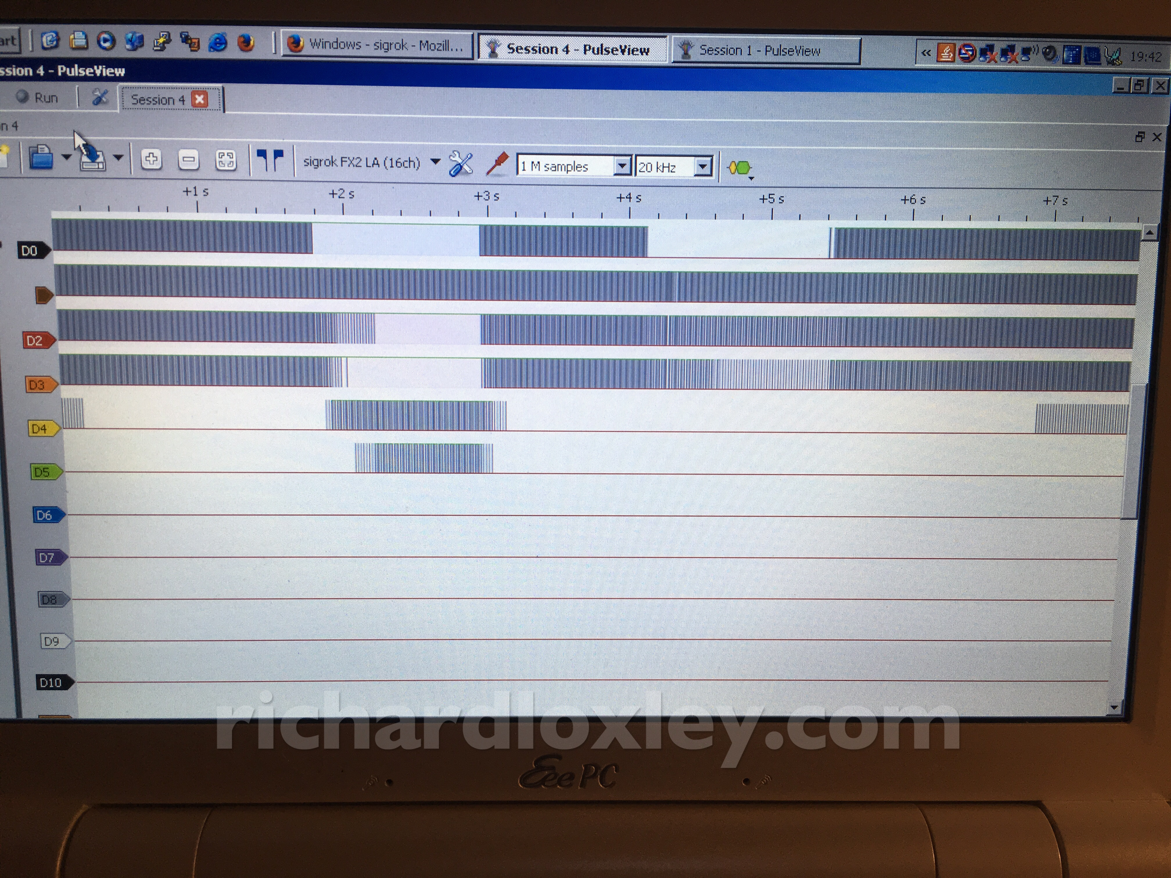
So it seems to work :-)
Nowhere can I find any instructions about the Hobby Components hardware, nor do any of the sigrok tutorials talk about the hardware side of things. I was presuming I’d need to hook up the ground line to the ground of the circuit being tested, but I couldn’t find anything to confirm that.
Eventually searching the net found a generic logic analyser tutorial, and that seems to confirm I need to connect the grounds.
So not bad for an hour of messing around. At least I achieved something this weekend!
The next step is to hook up the analyser to a known good computer to see the sort of signals I might be expecting to see, and to play around with the software to get familiar with it.
Next weekend maybe?
Just a quick note about grounds. You (almost) always have to connect the grounds together, which is why there is no mention of it. It is assumed that you will connect them. On the VERY rare occasion that you should NOT, that will be specified.
Thanks. A friend also pointed out that problems can occur if both the test device and the logic analyser have their grounds referenced to the mains earth (and I found a couple of videos explaining why). Thankfully my netbook power supply isn’t referenced to mains earth, so I should be good to use it to analyse any circuits I want :-)