In my previous posts I flashed HxC firmware onto a Gotek USB floppy emulator, and tested it with my Video Genie.
I’m now going to delve into the intricacies of the Shugart 34 pin floppy disk interface (emulated by the HxC firmware); the jumper settings on the Gotek hardware; and how to extend the hardware to do some cool stuff :-)
Gotek hardware
Here’s a look at the back of the Gotek USB floppy emulator:
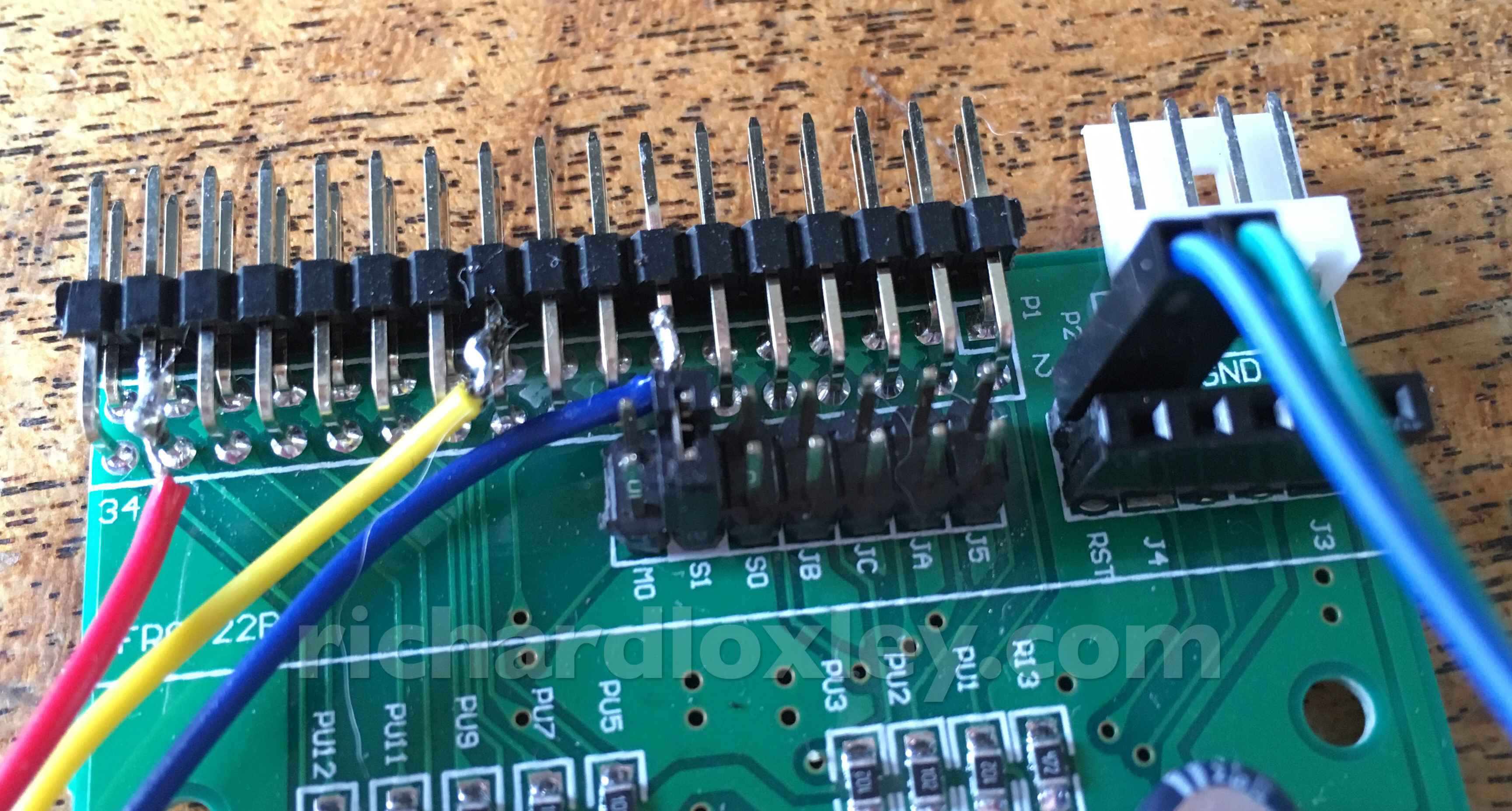
The black pins at the top left are the 34 pin floppy interface. The 4 white pins at the top right are the power connections.
In the second row on the left are some jumpers (marked MO, S1, S0, JB, JC, JA, J5).
In the second row on the right are headers that I have soldered on to provide power to an LCD display (the two blue and green wires), and to allow flashing of the firmware (the pins marked RST, J4, J3 and two unmarked pins).
Finally there are red, yellow and blue cables I have soldered directly on to the back of the 34 pin floppy interface – more on those later.
Shugart floppy interface
So to understand how the jumpers work, let’s first look at the definition of the Shugart floppy interface. This was a standard used by many disk drives in the 1980s, and was a precursor to the PC floppy disk interface.
Here’s a wiring diagram (taken from the Video Genie manual):
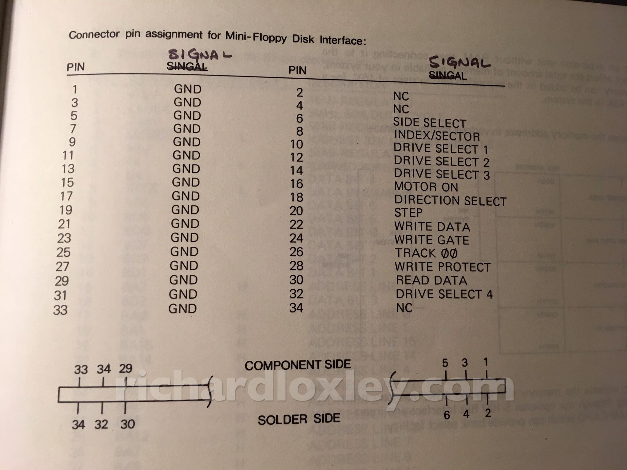
[N.B. Some resources label pins 6 and 32 the other way around – I’m not sure which is the original standard. Also pin 34 is usually a ‘ready’ signal, pin 4 an ‘in use’ signal, and pin 2 a ‘disk changed’ signal.]
The Shugart standard can control up to four drives. Some manufacturers refers to them as drives 0/1/2/3, others use 1/2/3/4. To avoid ambiguity I use A/B/C/D.
There are many common pins to pass data back and forth, and four pins (10,12,14,32) to select which drive should respond to the commands on those common pins. All lines seem to be pulled high (5v) by default, and are ‘active’ by being pulled to ground. The drive should only respond if the relevant drive select line is active (0v).
The one exception to this is the ‘motor on’ signal on pin 16. All drives should respond to this command, meaning that all drives connected to the interface spin up their motors regardless of whether they are being accessed. This seems counter-intuitive, until you realise that it takes several seconds for the motors to get up to the required RPM. So the ‘motor on’ signal is sent in advance, and then the drive is accessed once the drive has had a chance to spin up. A drive cannot use the ‘drive select’ lines to decide whether the ‘motor on’ signal is for that drive, as the computer may access different drives at quite short intervals (e.g. when copying from one drive to another). So the pragmatic solution is all drives spin up, just in case.
(As an aside, the PC floppy drive standard changed this, and went for separate ‘motor on’ lines for each drive. But to free up pins to allow this, they only allow drives A and B, with corresponding ‘motor A’ and ‘motor B’ pins.)
The jumpers
So back to the jumpers on the Gotek hardware. Of the jumpers JB/JC/JA/J5, only one is now used since I flashed the HxC firmware onto it (to add the extra button the upgraded user interface needs).
That leaves MO, S1, and S0. The documentation is not really very clear on them at all. But inspection reveals they are connected like this:
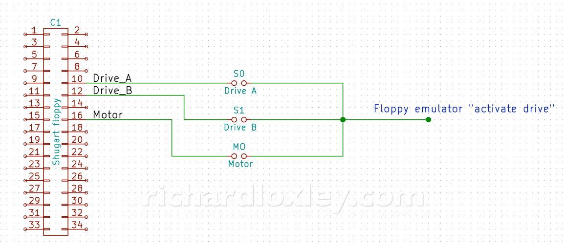
In other words, all the Gotek hardware needs to know is when to activate the emulator, and when to ignore commands destined for other drives. You can connect a jumper in one of the three positions to get it to respond to Drive A, or Drive B, or to the ‘motor on’ signal. That last one is interesting, as it will then always respond if any drive is being accessed. If you have multiple drives connected, then it will clash with the other drives, but if the Gotek is the only drive, it means it will always respond, without worrying about setting the jumpers correctly. So if you only ever use it as a solo drive you can set the jumper to MO and forget about it. Clever!
Extra jumpers for C and D drives
So now to my enhancements. My first plan is to allow the drive to be used as C or D, as well as A or B. (My Video Genie has two real floppy drives, A and B, and it would be good to be able to use the floppy emulator as a C drive alongside the real drives to copy files.)
My plan is to bypass the jumpers and replace them with a rotary switch. I can then also connect the drive select pins for Drive C and Drive D from the 34 pin connector to the switch:
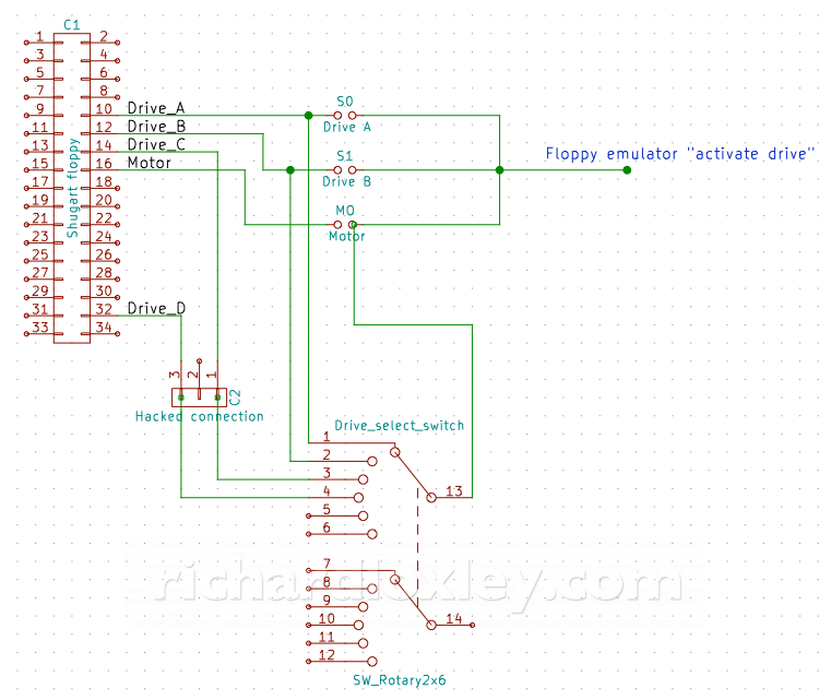
Remember those coloured wires soldered on to the pins in my first photo? The blue and red wires are the Drive C and Drive D pins respectively.
[N.B. Some wiring diagrams have Drive D on pin 6 instead of pin 32. Should I add an extra switch option to give A, B, C, D(6), D(32)? Or just use A, B, C and forget about D as three drives will be sufficient? I can’t decide.]
Supporting the Amstrad CPC 6128
My second enhancement is to allow use of the floppy emulator with my Amstrad CPC 6128.
Amstrad initially introduced their disk interface for the CPC 464 with the DDI-1 (Disk Drive Interface 1) and the FD-1 (Floppy Drive 1). The DDI-1 added disk commands on a ROM, and a cable where you could connect up to two FD-1 drives.
To make the configuration easier, they didn’t require jumpers to tell the drive to behave as A or B. Instead they made the FD-1 respond to both drive select A and drive select B pins! But they wired up the floppy cable so that the drive select A pin was only connected on the first floppy connector, and the drive select B was only connected on the second connector. That meant it was ‘plug and play’ for users.
The CPC 6128 had an internal floppy, and they carried on the same interface model for the port that allowed a second floppy drive. But that means that the external floppy port is only wired for drive select B, so any drive connected there can only act as Drive B.
Ideally I want my floppy emulator to be able to act as Drive A on the 6128, as some software will only work when loaded from Drive A.
Thankfully there is a hack to allow this to work.
I’ve found several references to connecting pins 11 and 12 together on the 34 pin floppy interface to allow the external drive to act as an Amstrad CPC 6128 Drive A (reference 1, reference 2, reference 3, reference 4). But no one has ever explained why (as far as I can tell).
Now I’m not one to blindly follow instructions without understanding them! Particularly if I’m trying to make a generic product that will work with other devices. So I set out to work out how this hack works.
I found a schematic for the Amstrad 6128 disk interface. Following the drive select pins back from the drives, leads to this section of the circuit. (Ignore the pin numbers on the interface, the internal drive uses a 26 pin interface instead of the 34 pin version, and the external drive is numbered in a non-standard way as Amstrad used the 34 pin connector rotated by 180º!)
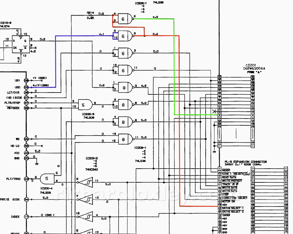
I’ve marked the interesting bits in colour. It seems that the Amstrad only uses one digital output (US0: marked blue) to toggle which drive is being accessed. This is then sent through a NOT gate to produce the drive select B for the external interface (marked red). Meanwhile the drive select A for the internal drive (marked green) is created by another NOT gate whose input is pulled high with a 5v line and a resistor. And then the drive select B is also connected to the input of the NOT gate for drive select A .
The upshot of this is the internal drive (A) is normally active (5v -> NOT -> 0v, which means the drive is selected). But if US0 is high (5v), then the external drive (B) is active (5v -> NOT -> 0v to select the drive). And the action of selecting drive B deselects drive A (drive B = 0v, which is connected to the NOT gate for drive A, which pulls the input low because of the resistor between it and the 5v line, and 0v -> NOT -> 5v which deselects drive A).
This also explains a quirk of the Amstrad when you have two drives connected. Because it only uses one bit to toggle the active drive, it means one drive is always active, even if it isn’t being accessed. On a twin-drive system, the LED for drive B is always lit, unless you read drive A, in which case the drive A LED briefly comes on and the drive B LED goes out.
So this now explains how the pin 11 – pin 12 hack works. That connects the drive select pin for drive B to ground (that’s the red line in the diagram). So whichever drive the Amstrad tries to access (using the blue line), the red line always stays at 0v. And the green line (for the internal drive) is always set from the red line, so that keeps the internal drive permanently inactive.
So providing the external drive is jumpered to respond to drive select B, connecting pin 12 to ground will make the external drive respond to any drive letter (including drive A), and will also deactivate the internal 6128 drive. Nice!
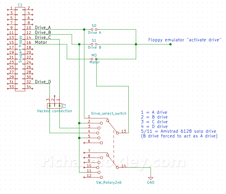
So now here’s the circuit I intend to use to add a fifth option to my rotary switch (A, B, C, D, 6128 solo drive). The fifth position will jumper the emulator as drive B, and by using a double pole switch it can also connect pin 12 (drive select B) to ground:
Amstrad CPC 464
The Amstrad CPC 464 presents an extra challenge above the 6128. People have used floppy emulators as B drives using the DDI-1 interface with the 464, but no one has successfully used one as drive A.
The reason is that the DDI-1 doesn’t quite conform to the Shugart standard. It replaces pin 14 (drive select C), pin 6 (side select or drive D select), pin 4 (in use) and pin 2 (disk changed) and expects all four to be connected to 5v.
This is because the DDI-1 interface requires a 5v power source to power its circuits. If you connect an FD-1 to the ‘drive A’ position on the cable, it delivers the 5v down the ribbon cable on those four pins. There are three possible reasons why Amstrad did this:
- Perhaps they didn’t think the Amstrad CPC 464 could reliably deliver enough current for the DDI-1?
- Perhaps the DDI-1 needed powering up earlier than the 464 to enable it to register its ROM routines during the 464 boot-up sequence? Indeed people have hacked the DDI-1 to take its power from the 464, and some say that occasionally it fails to load the ROM routines with that hack.
- Perhaps they wanted to stop people buying cheap 5.25″ and 3.5″ drives and connecting them to the DDI-1, rather than buying the propriety FD-1?
I’ve come across reason 3 many times in my research, but no evidence to back it up. I personally feel reasons 1 and 2 are far more plausible for this design decision. It seems a very low-level design decision to be influenced by such marketing pressures.
Anyway, I’d prefer not to modify my DDI-1 (I don’t like irreversibly modifying vintage hardware, and it might also cause issues using the DDI-1 with an FD-1 in the future).
I’ve wondered about having a switch on my RetroMatic 2000 box to activate 5v power on the relevant pins. But that could be very dangerous if I forget to switch it off when connecting to other computers!
I’m going to need an extension cable anyway to get the floppy connector outside the box. No one sells 34 pin male to female floppy cables any longer (except specialist retro places in Europe for exactly this purpose, at vast expense).
So it’s most effective for me to buy the connectors and wire up my own floppy extension cable.
Since I’m doing that, I could wire a custom extension cable with two sockets at the end. I can have an additional 5v wire going to the second socket and connect it up to the relevant pins.
I can paint the 5v socket red as a warning that that socket is only for the Amstrad. Or just write on the cable in big letters next to it. Then you just plug into the correct socket for the computer in question.
This also solves the problem of the Amstrad 34 pin connector having the key-way reversed 180º since I’ll be wiring up a dedicated Amstrad socket!
You could probably even leave multiple computers connected provided only one was powered on at a time ![]()
Sound effects
The original HxC hardware came with a speaker and emulator for a floppy drive sound. But the Gotek hardware running the HxC firmware doesn’t (yet) support this. The author of the firmware has said he wants to add this, but it’s nearly two years since he announced his intention, and nothing has yet materialised (reference 1, reference 2).
I’ve found four basically similar sound mods suggested for the Gotek hardware. They all use the ‘step’ signal on pin 20 to make a ‘click’ sound on a speaker to simulate the click you’d get from a stepper motor moving the disk head. (Design 1, design 2, design 3, design 4.)
I might still do one of these, but I’m tempted to go a bit further. My reasons are:
- They all require extra components that I’d need to buy (and fit somehow on my circuit board).
- They only use the ‘step’ signal, not the ‘drive select’ signal, so the sound effects occur for any drive on the cable, not just the emulated drive.
- They only simulate the head step sound, not the motor sound.
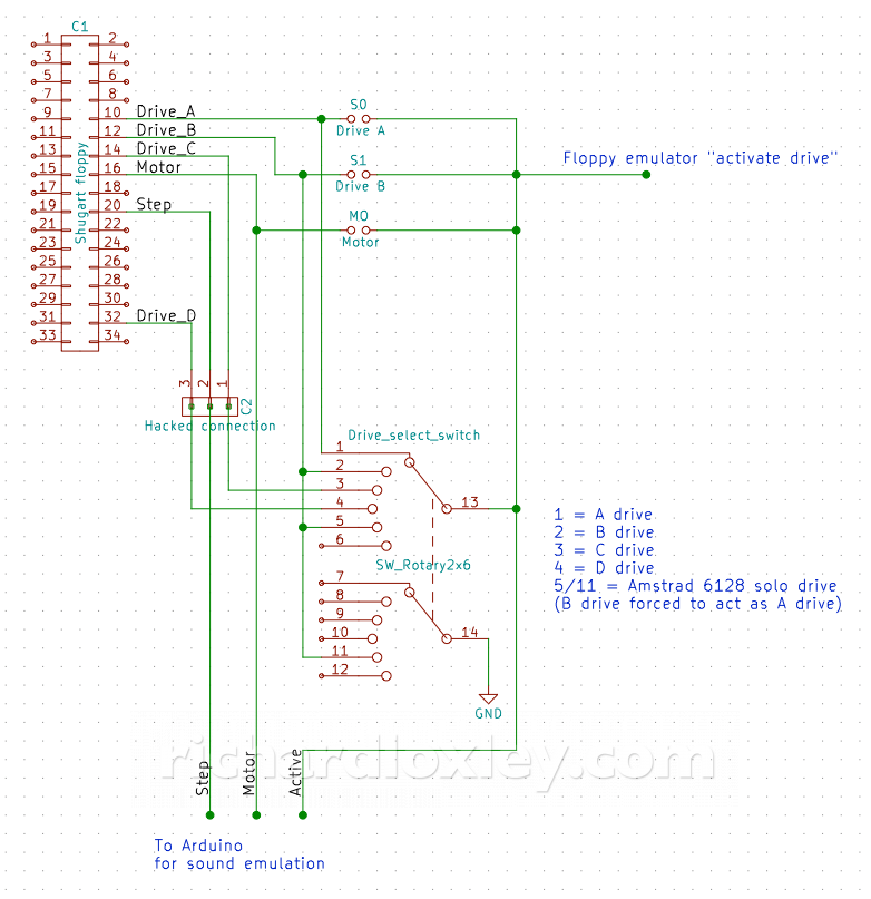
So my plan is to feed the ‘motor on’, ‘drive select’ and ‘step’ signals to the Arduino I’m using, and then try to simulate the sound effects in software. I’m not sure if that will work, but if it fails I can always go back to the hardware solution :-)
Here’s my final circuit including the sound effect interface (the ‘step’ signal is the yellow wire I soldered on to pin 20 in my earlier photo):