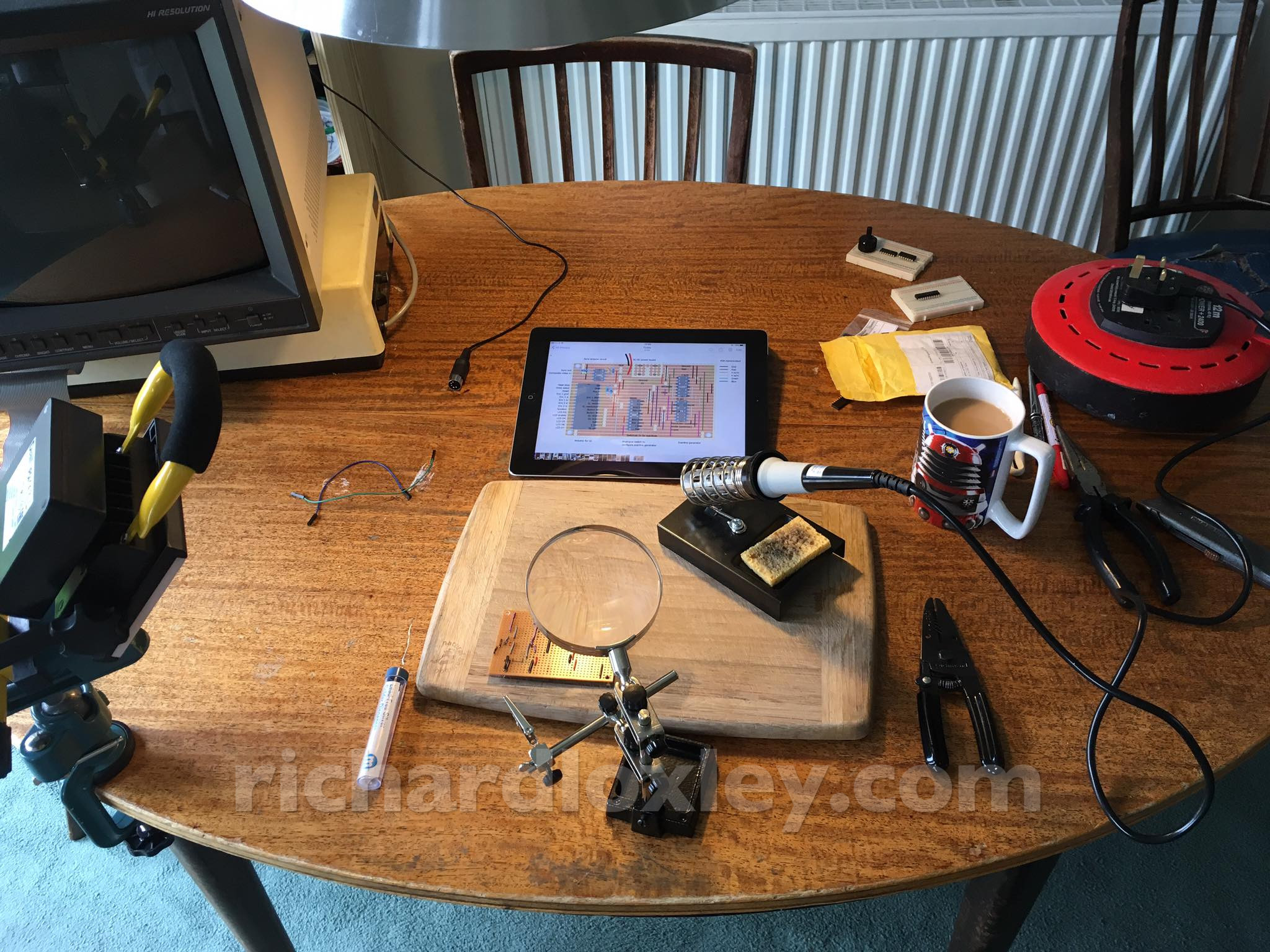
It’s the last day of the Retro Challenge, so I’m going to try to solder up the main circuit board, so I get a finished product, rather than just a collection of breadboards.
All set for a day of soldering. Including a cup of tea in my favourite Dr Who mug ![]()
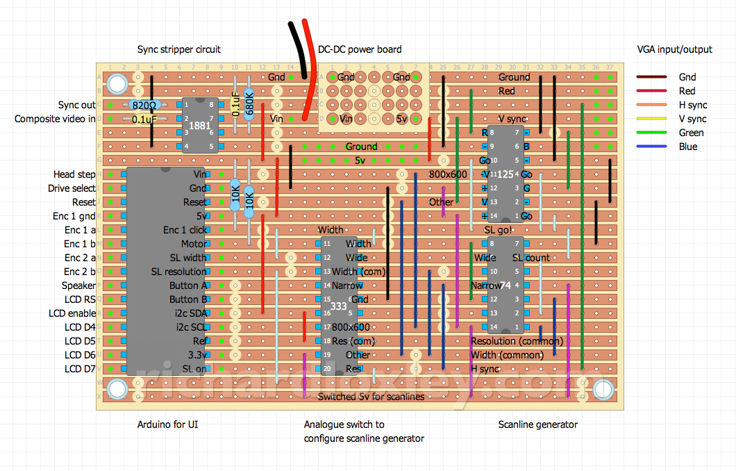
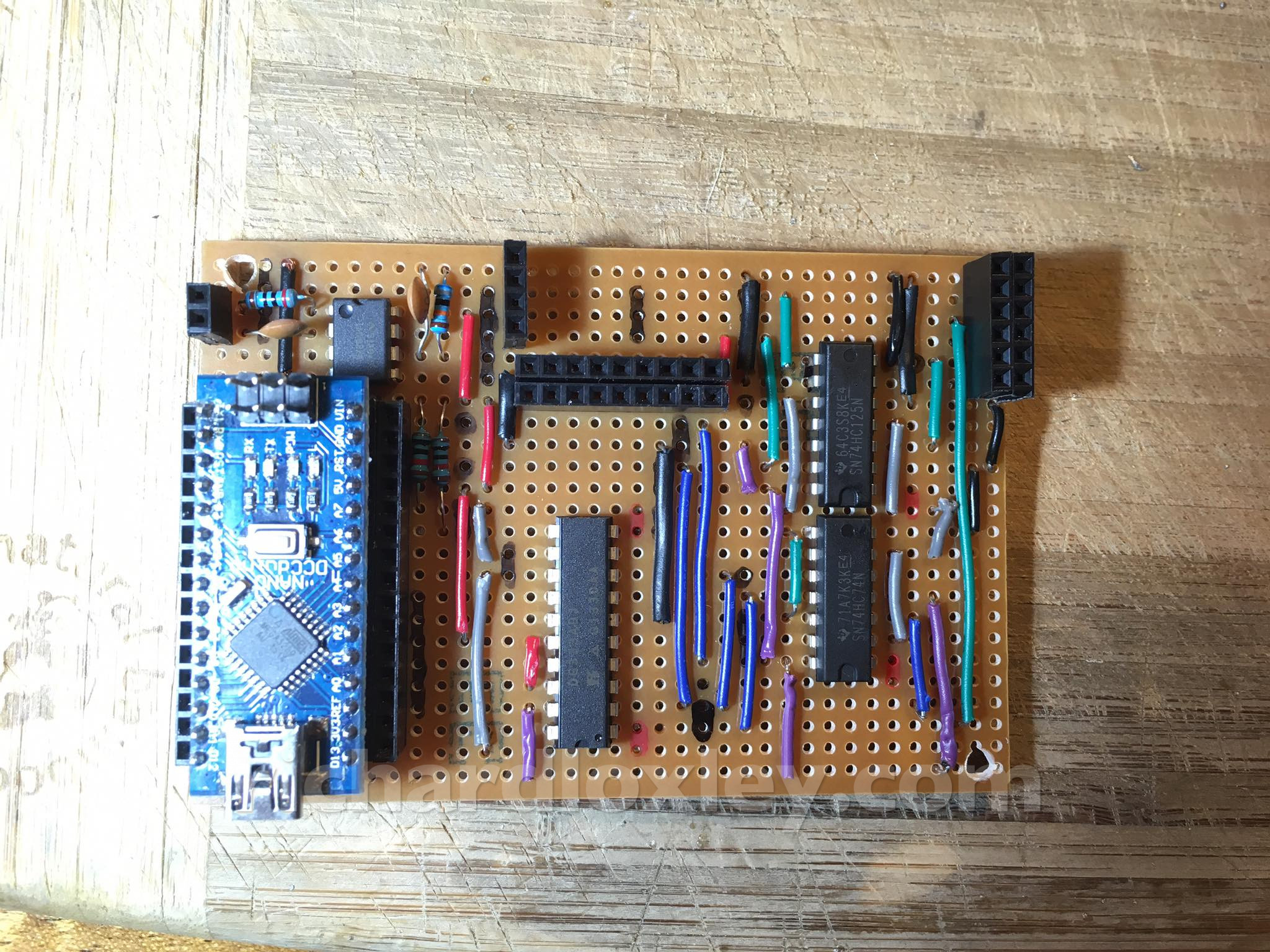
This is the final final circuit board, with a few tweaks made last night (mainly extra power headers for the satellite boards):
Off we go!
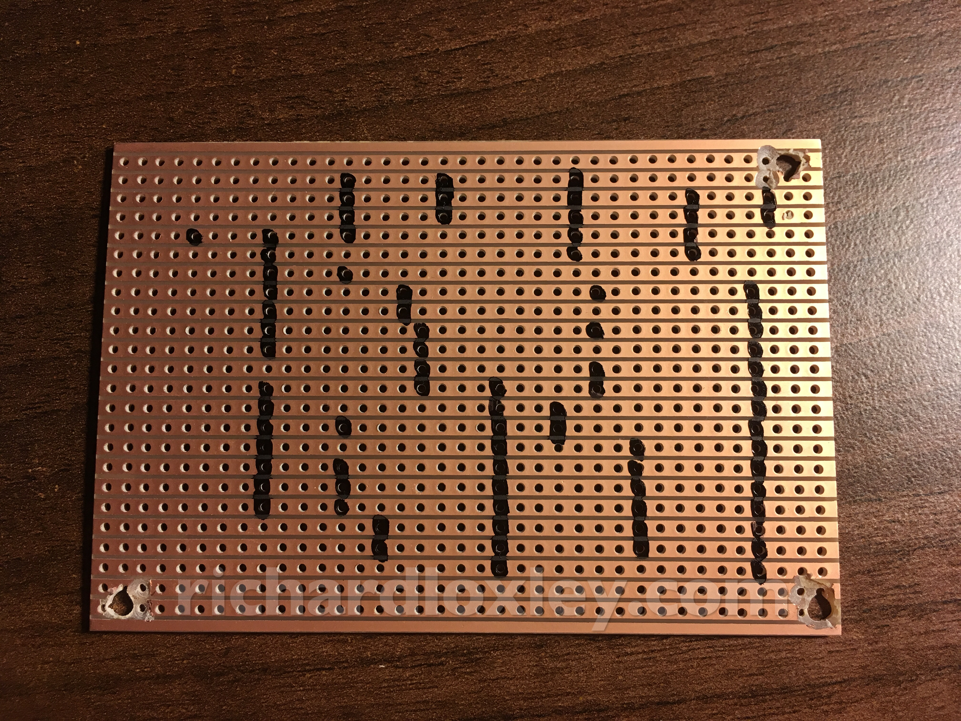
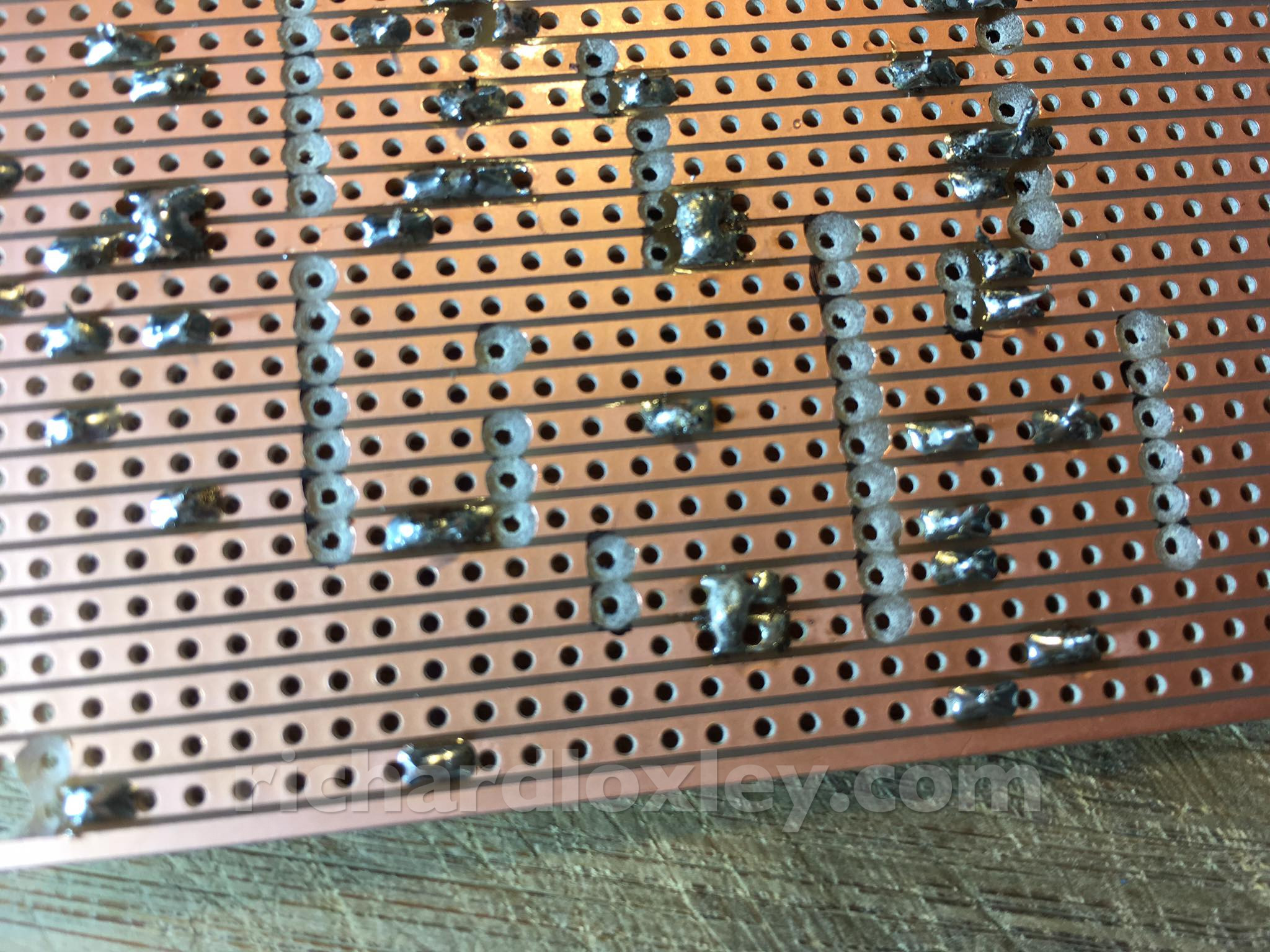
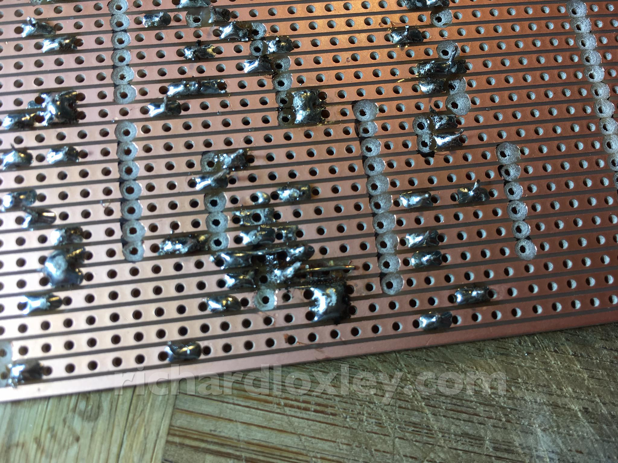
Marking out the veroboard where I need to cut the traces, and making the cuts.
I verified all the cuts and traces afterwards with a multimeter to make sure I’d done it right. It’s been about 35 years since I last did this!
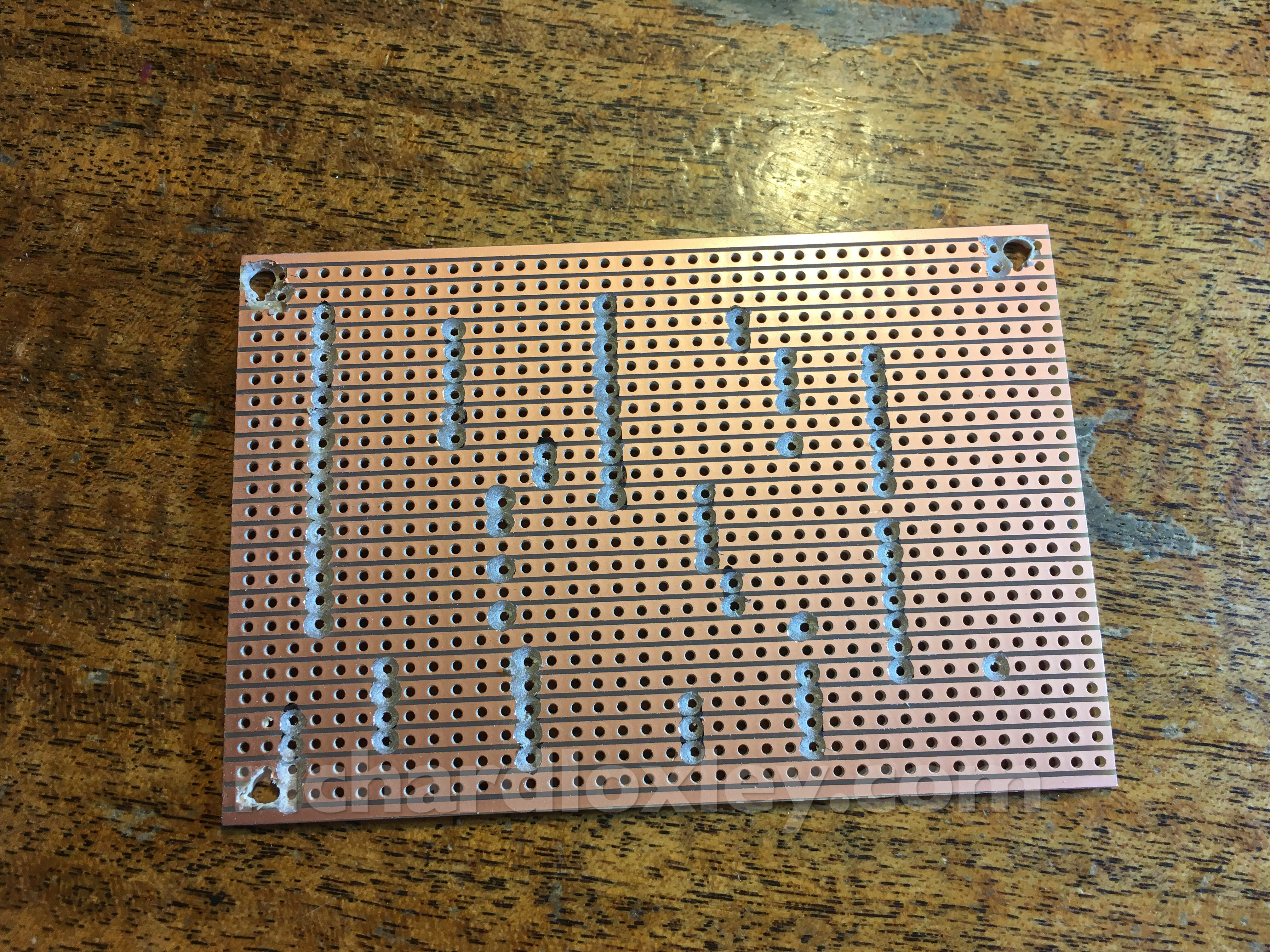
Oops. The two hole break in the middle (3 holes up from the bottom) is in the wrong place. It should be 2 holes from the bottom. And I lined up some wires relative to it, so they need to be moved too.
Fixed it with some patch wires. Broke a bit of track in the process, so there’s a patch wire hanging in mid air ready to to solder to the pin of an IC when it gets fitted later ![]()
All wires done. I managed to keep to a reasonably sensible colour scheme to show the logic.
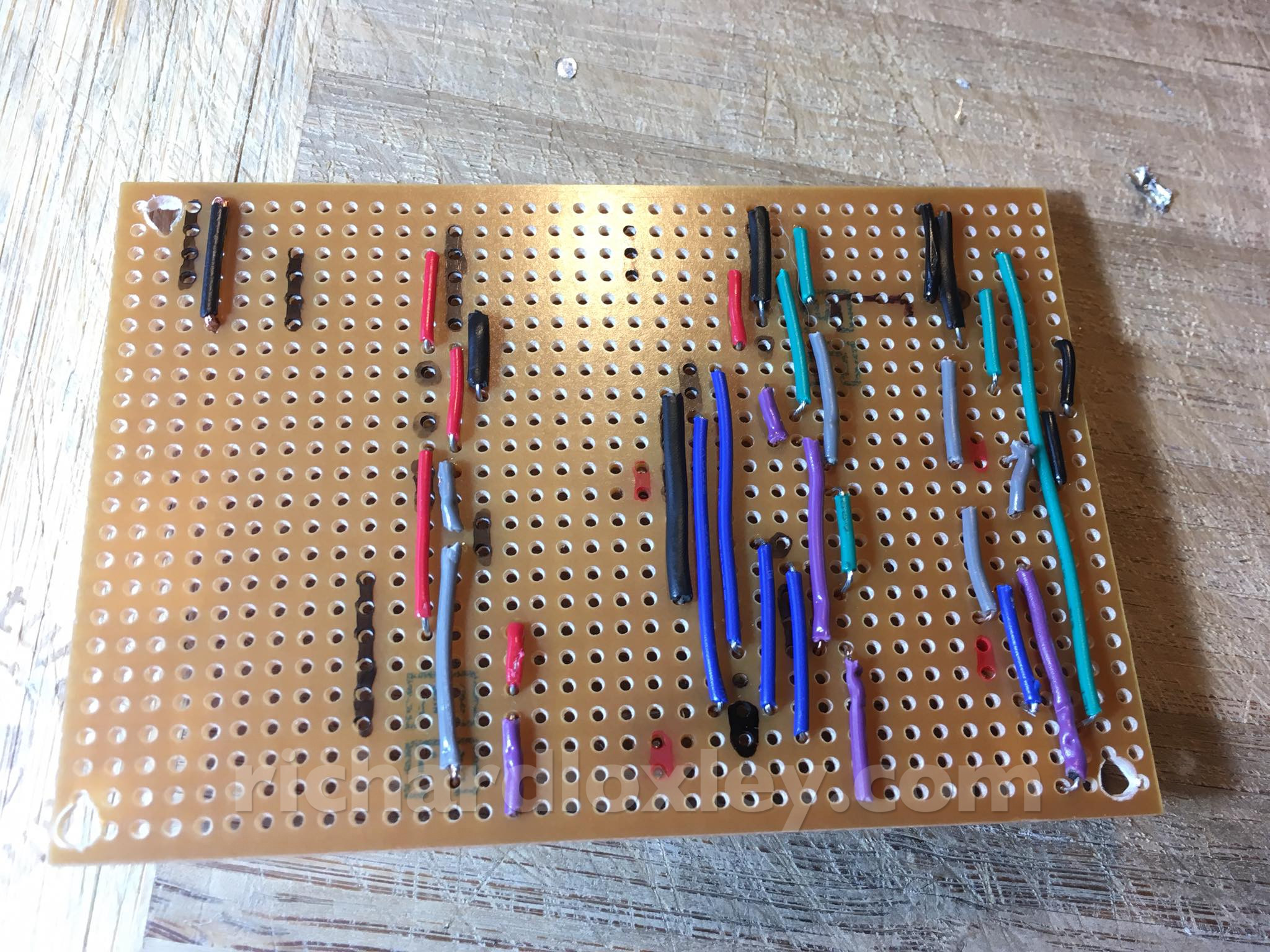
Red is 5v, black is ground. Purple is switched 5v to power the scan line generator as required. Grey is logic triggers. Blue is configuration of the scan line generator. Green is external input from VGA (apart from one internal logic line in the scan line generator which is also green).
Black marks are where there are cuts on the other side. Red marks are where I bridged tracks on the other side rather than bothering with a tiny wire.
Headers, resistors and capacitors added. I had a panic when my Arduino didn’t fit the headers – it turned out I’d soldered the header in the wrong place. 15 pins to unsolder let me perfect my unsoldering skills though!
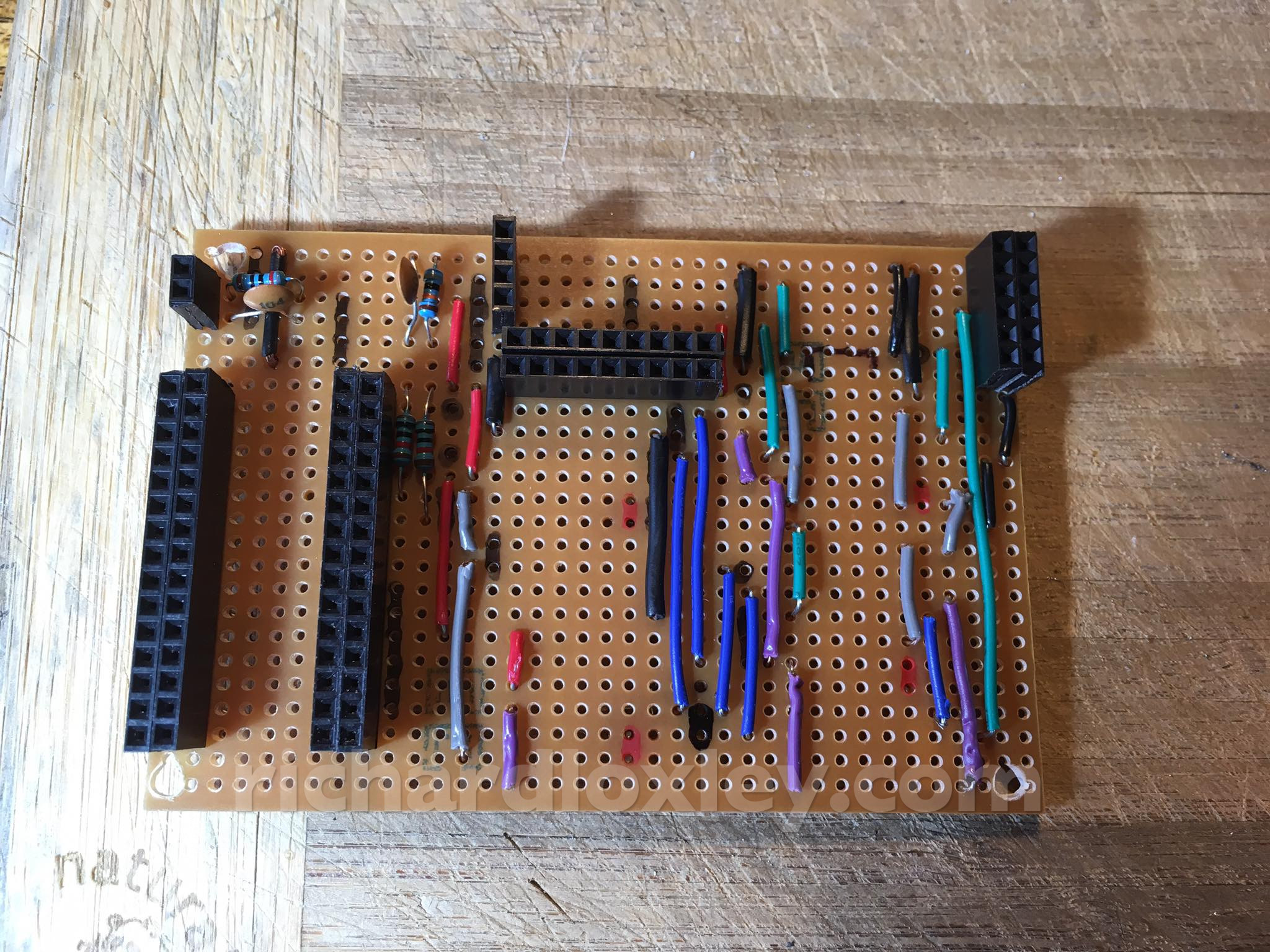
Now the ICs. I’m nervous about buggering them up with my soldering. Most are cheap (although I don’t have replacements to hand) – but one is nearly £5.
I don’t currently have any IC sockets (I must order some). I tried female DuPont headers but they were too loose.
I think that’s complete. I managed to solder the ICs with a maximum of 3 seconds per pin, so hopefully ok ![]() . I wonder if it will work?
. I wonder if it will work?
Well it mostly works. In that everything works as well as or better than it did on the breadboard, which is a good thing!
The scanline generator works, and now does wide scan lines are well as narrow. However the software switching of scan lines on and off doesn’t work. On inspection my analogue switch switches the scanline generator power supply between 2.5v and 5v instead of 0v and 5v. I’ll investigate why at a later date.
All the UI components work exactly as before. But I’ve now added a cool startup bleep. Every bit of retro kit has to have a cool startup bleep ![]()
I’ve plugged the Amstrad video feed through the the sync stripper. The Amstrad has clean sync anyway, so doesn’t need it, so it’s not a perfect test! But the video still works (which is how it should be) so the sync stripper is probably working correctly, I just need to do a more comprehensive test later.
Now to assemble everything, and make a video for my final submission for the Retro Challenge. Only 3 hours left ![]()