It’s time to build all the user-interface components for my RetroMatic 2000 into the wonderfully retro case I acquired.
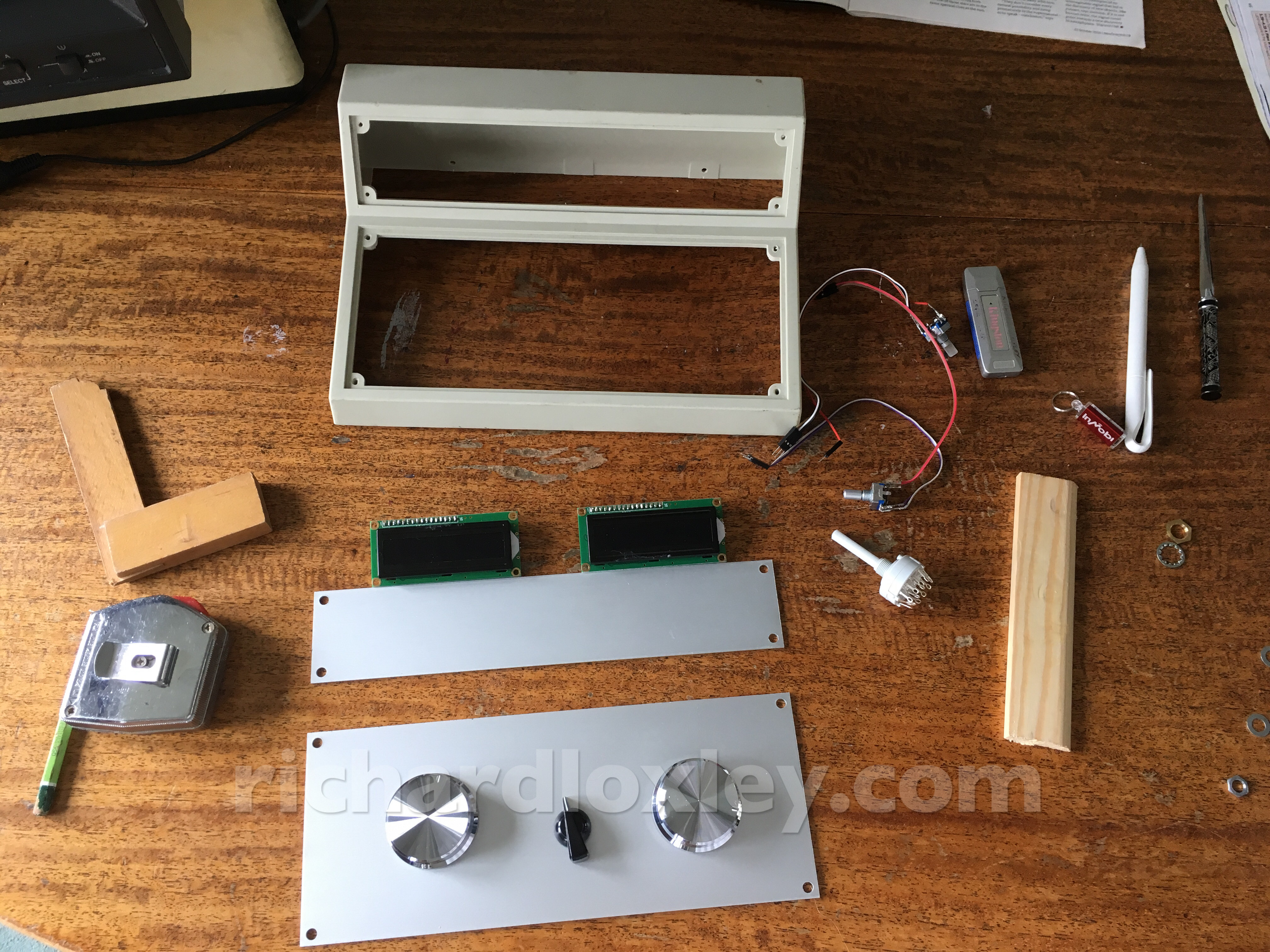
First off, lay out all the components, and plan where they are going:
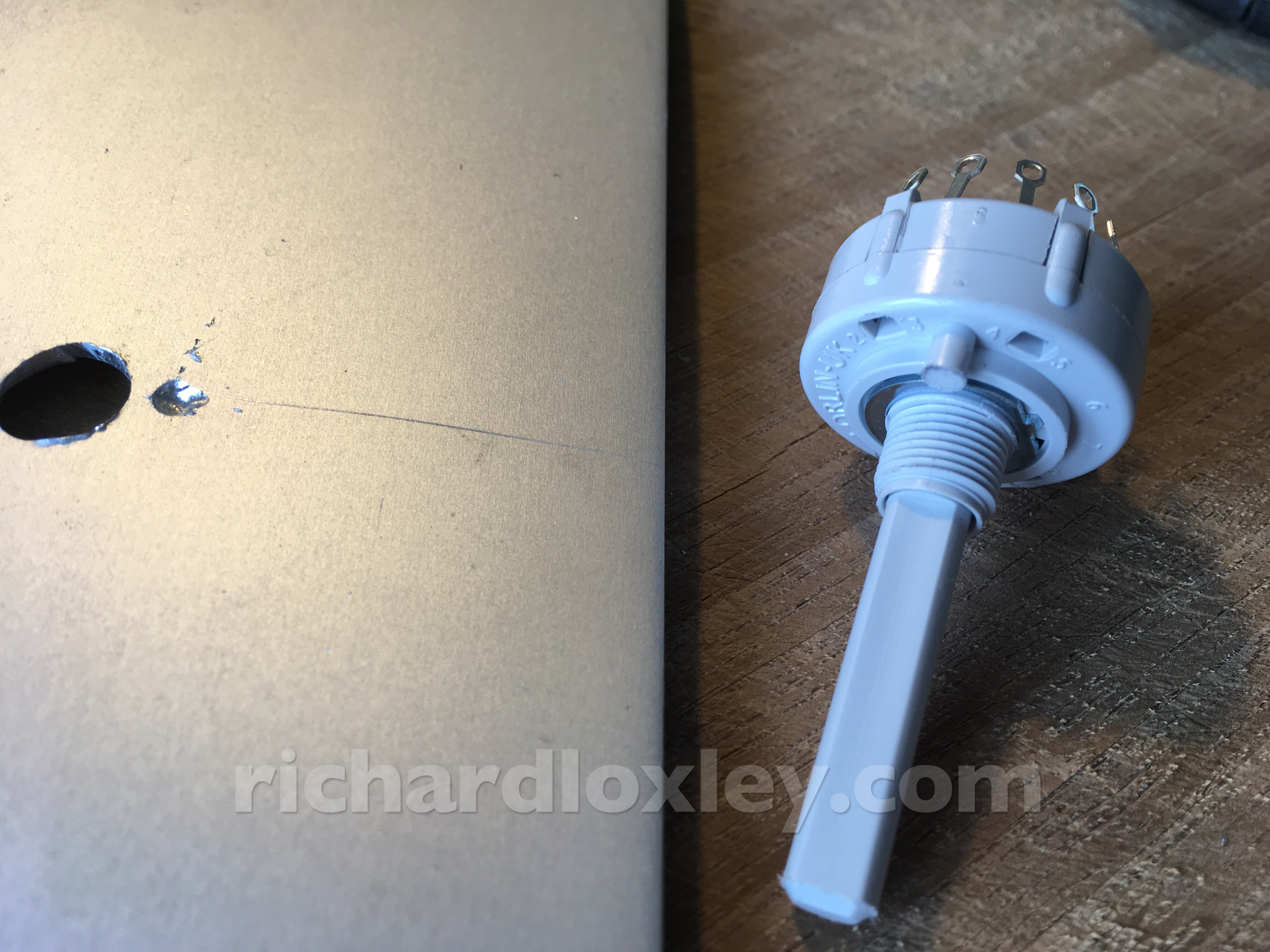
I drill a hole for the rotary switch. Rather cleverly, it has a “stud” to locate it, so it doesn’t spin round in its hole. Sadly the knob I have won’t cover the hole for the stud, so I have to drill a small indentation and file down the stud to fit:
Oops, I’ve let the magic ball bearings out of my rotary switch!
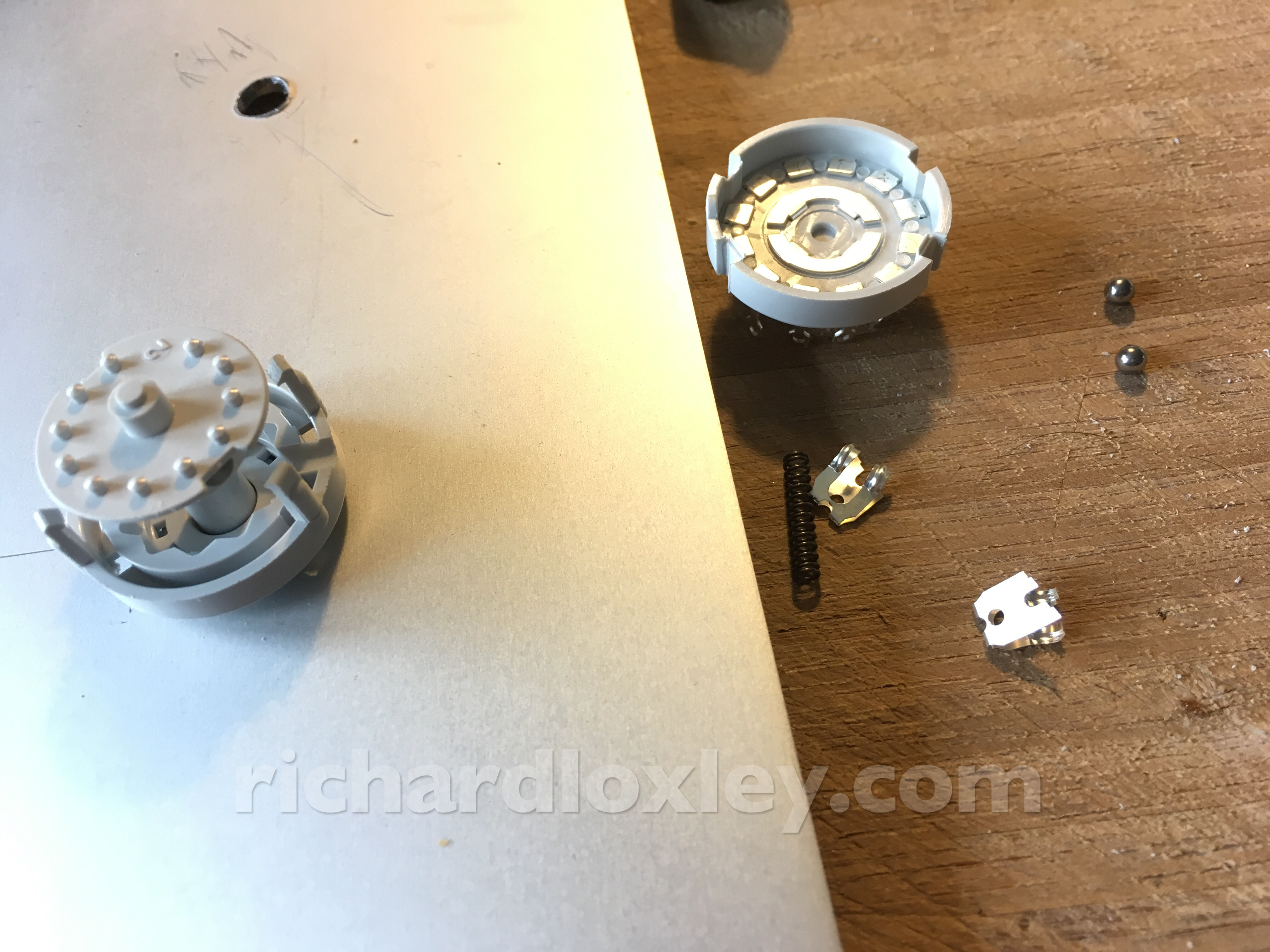
(I pressed too hard when trying to squeeze my knob onto it and everything exploded. Ooh err missus.)
It’s all right, I managed to reassemble it correctly, and I got to work out how it worked ![]()
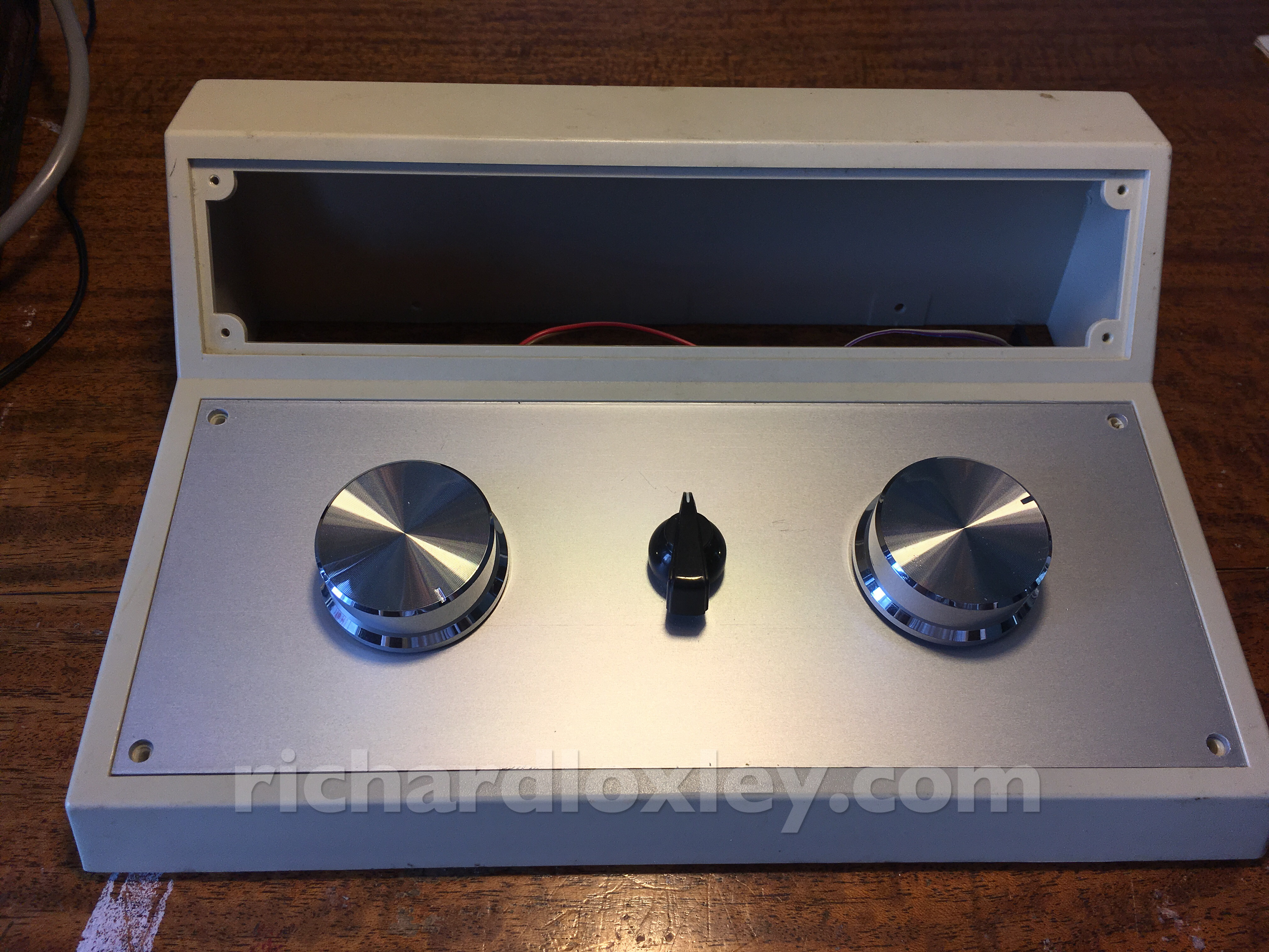
Knobs installed! Now to cut holes for the LCD displays. They need a very neat edge so it’ll be hard to do a good job!
Careful marking out for the LCD holes:
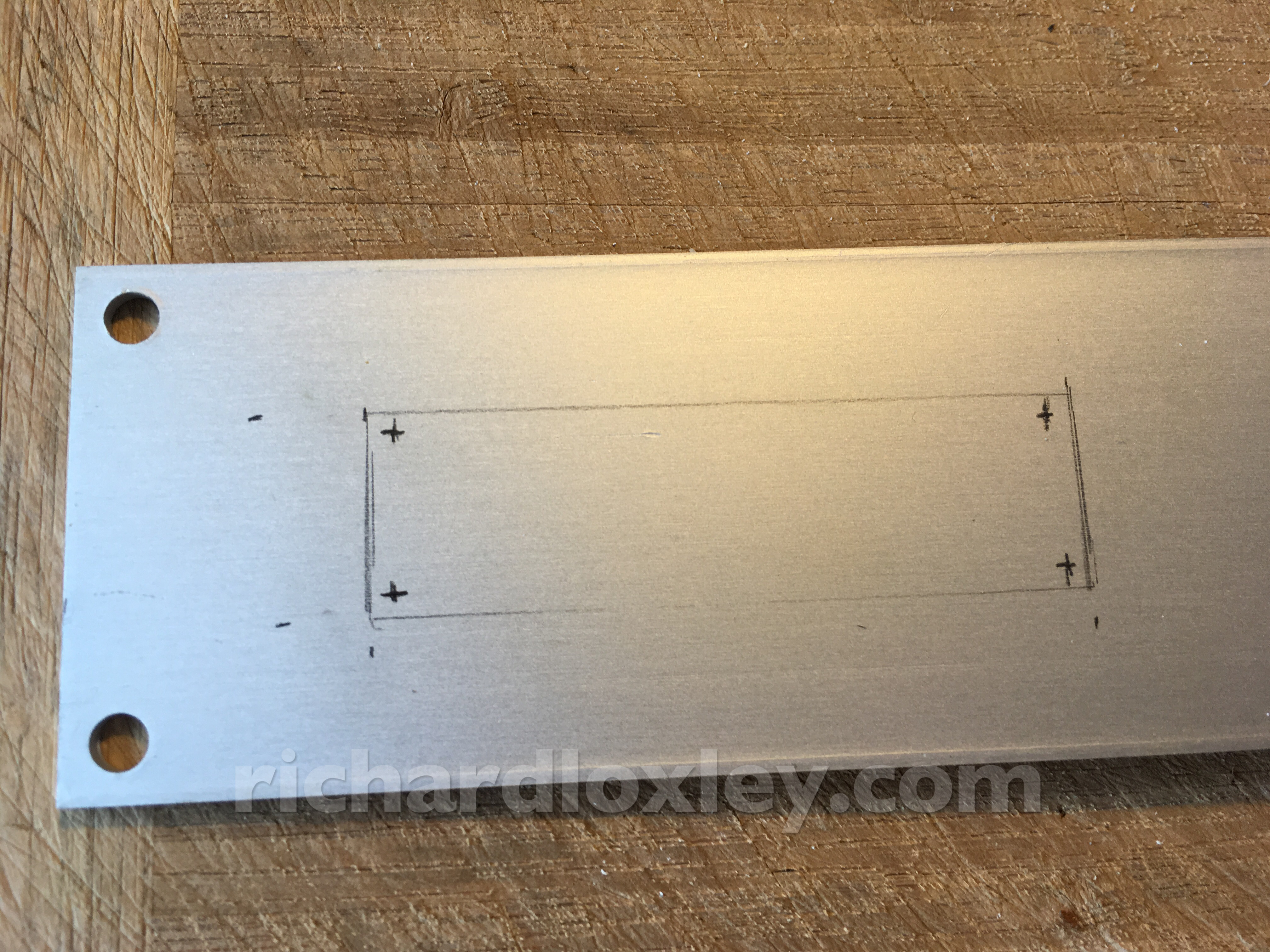
I’m going to mount them behind the holes with hot glue, so the display just floats behind the hole. It should look good if I get it right, but the edges of the hole will be very visible so I need to get a good finish.
I’m planning on drilling out the corners with a 4mm drill (hole centres marked 2mm in from the edges). Then I’ll cut out the edges.
Ideally I’d use an abrafile (is that the correct spelling? – I haven’t used one since school). But I don’t have one, so let’s see if the aluminium is soft enough to use a coping saw on. If not I can probably get the blade of my junior hacksaw in there, but it might not be too accurate.
Of course, if I mess up I can always put a card surround over the metal. I might do that anyway to give appropriate branding to the product.
Well the coping saw “coped” with the aluminium. Not the neatest job. Time for some filing!
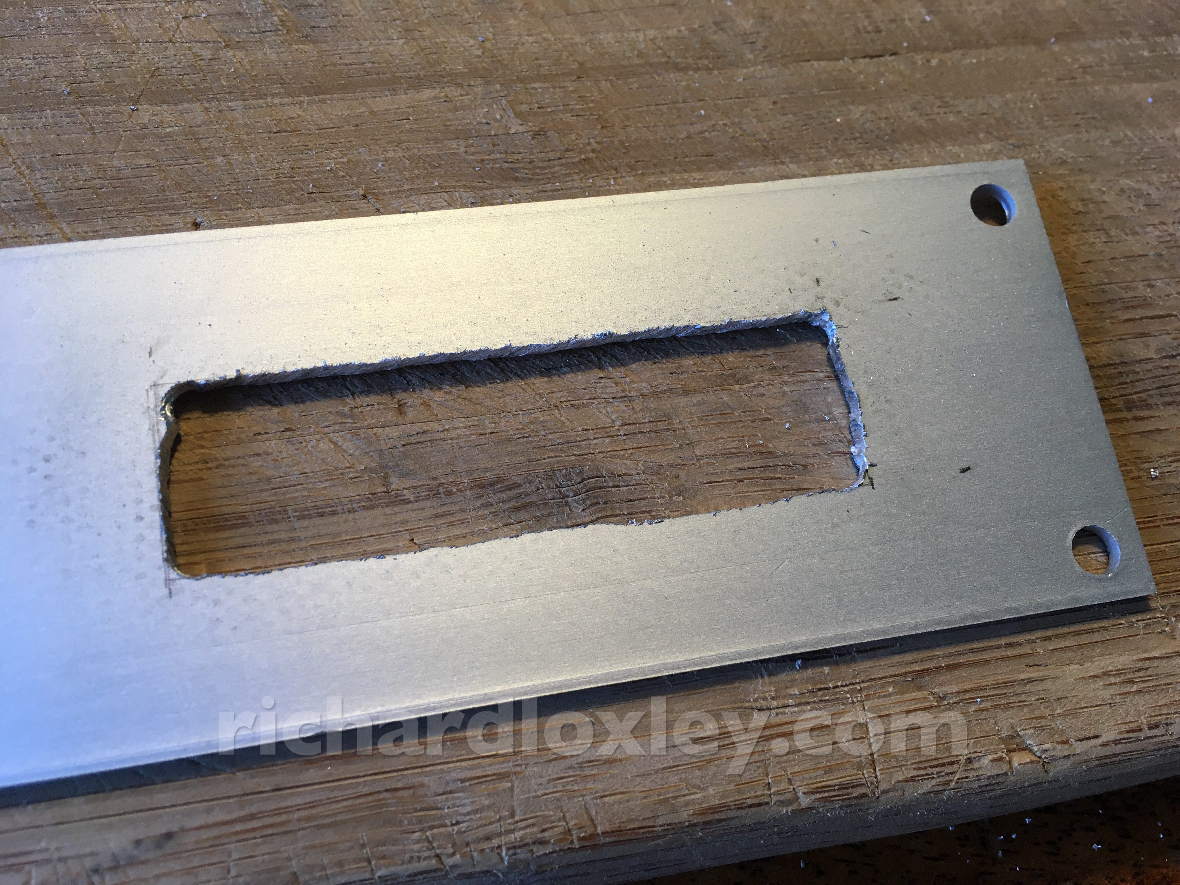
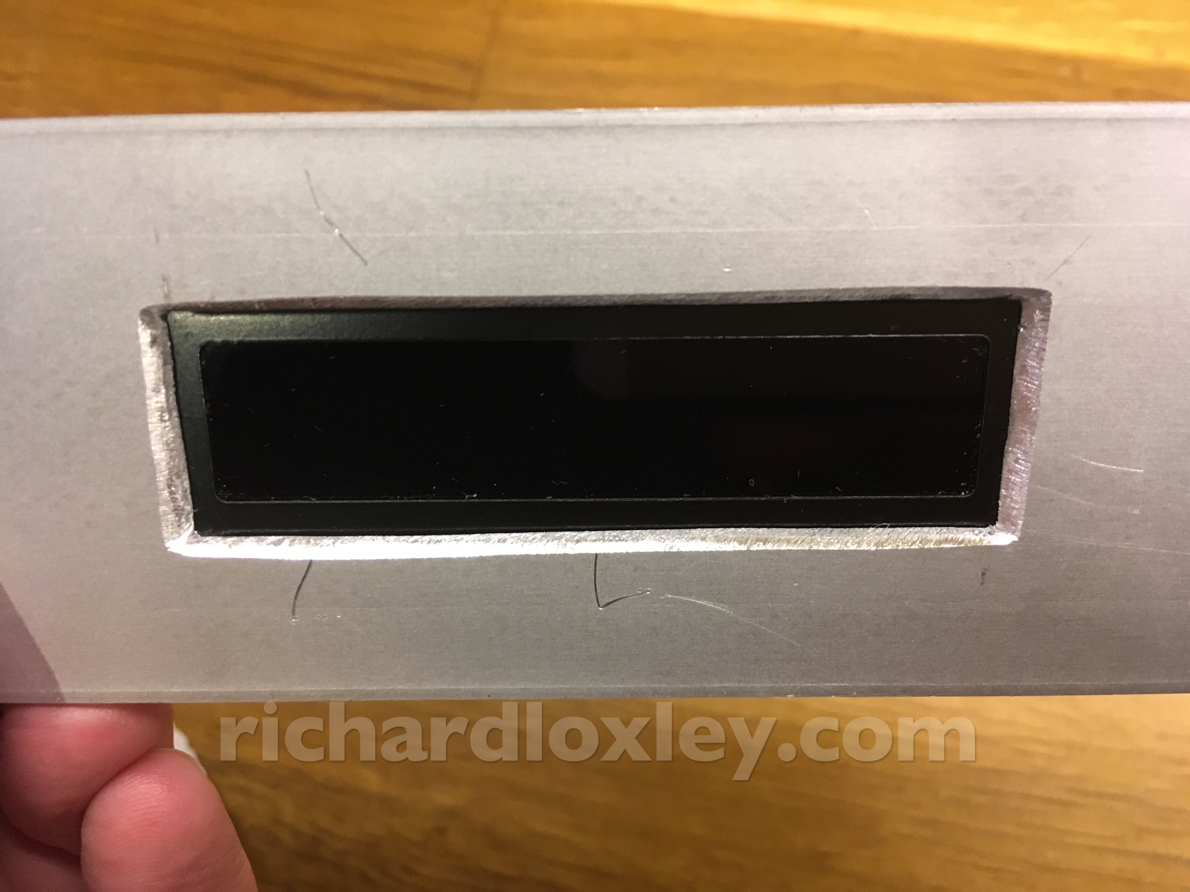
First LCD hole cut and filed. Not my best job, but acceptable. I’ll cut the second one now, and see how good that is before deciding whether to revisit this one to tidy it up some more!
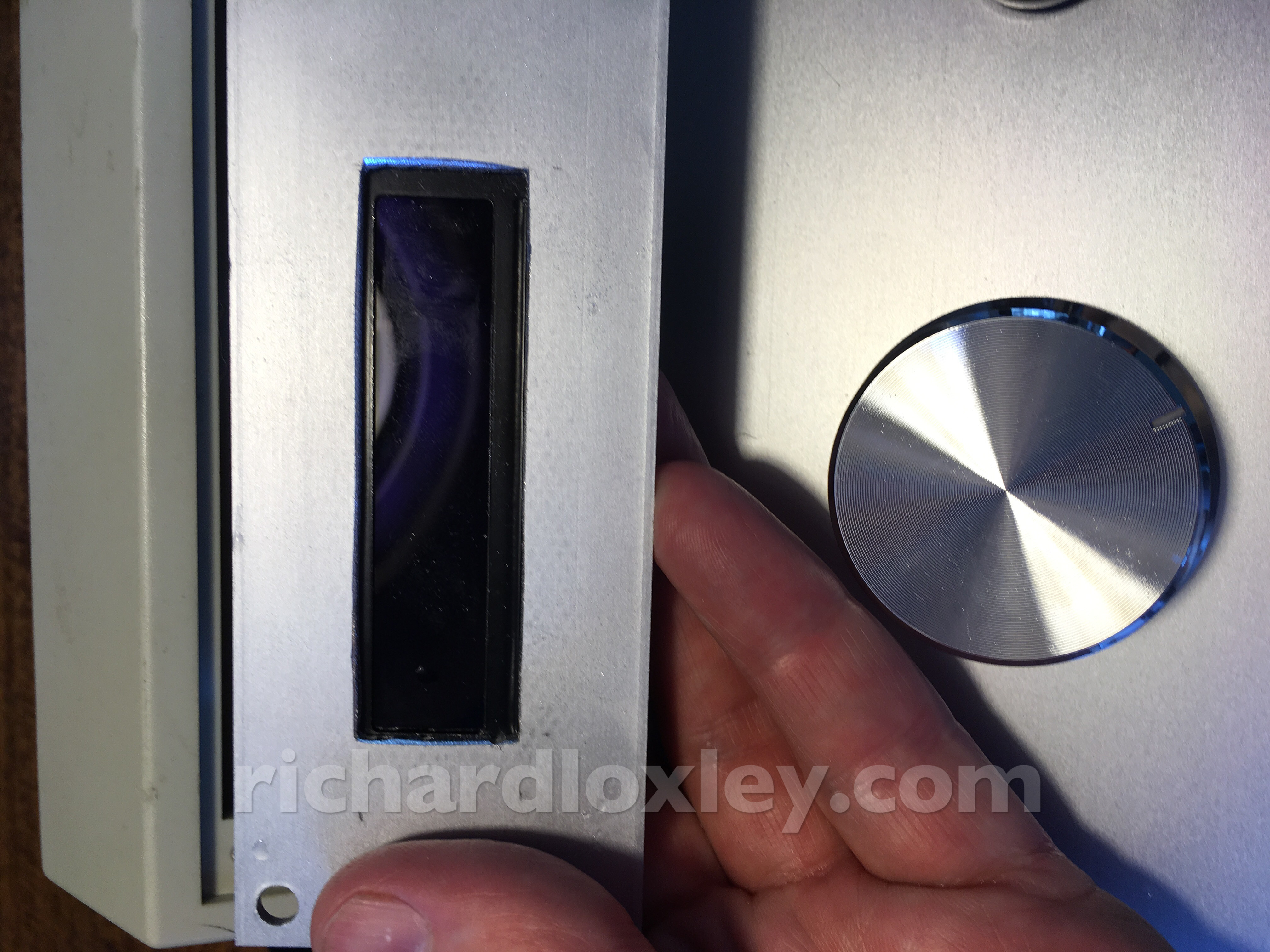
The second hole cut. Time for some serious filing to straighten up those edges.
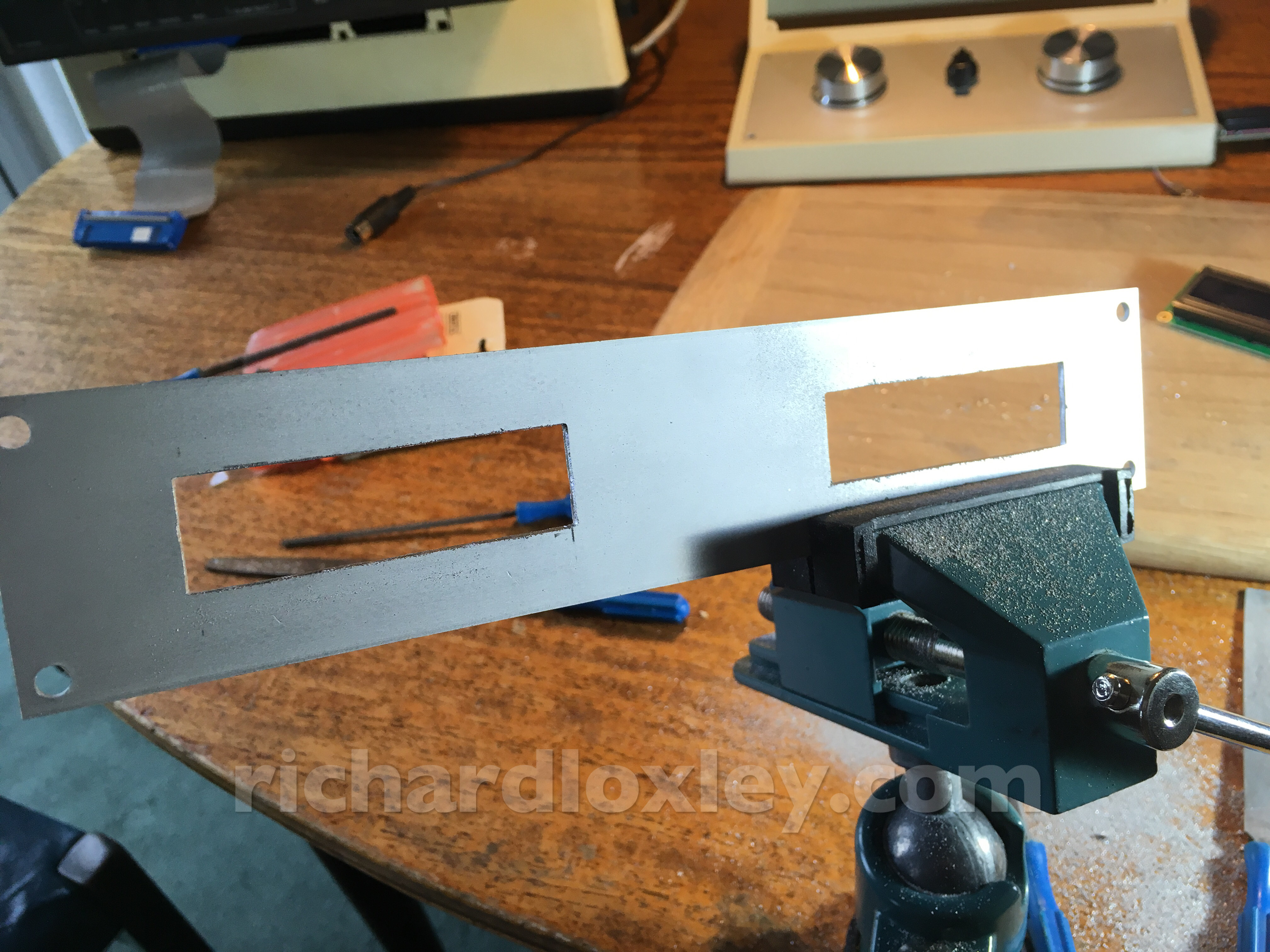
I also added some chamfers. Still not perfect, but good enough. Sadly during the chamfering my file slipped a few times, leaving marks on the aluminium face :-( Oh well.
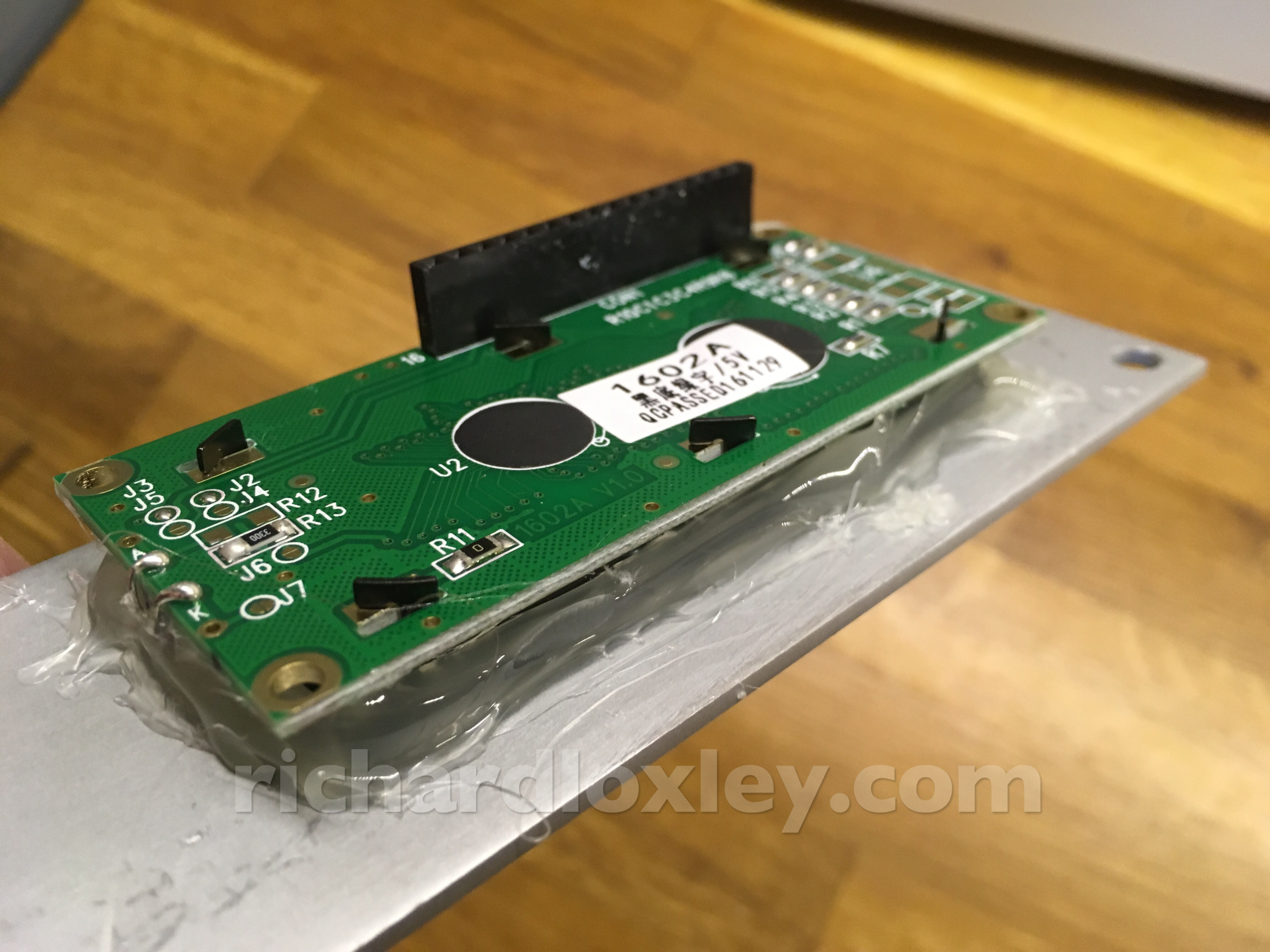
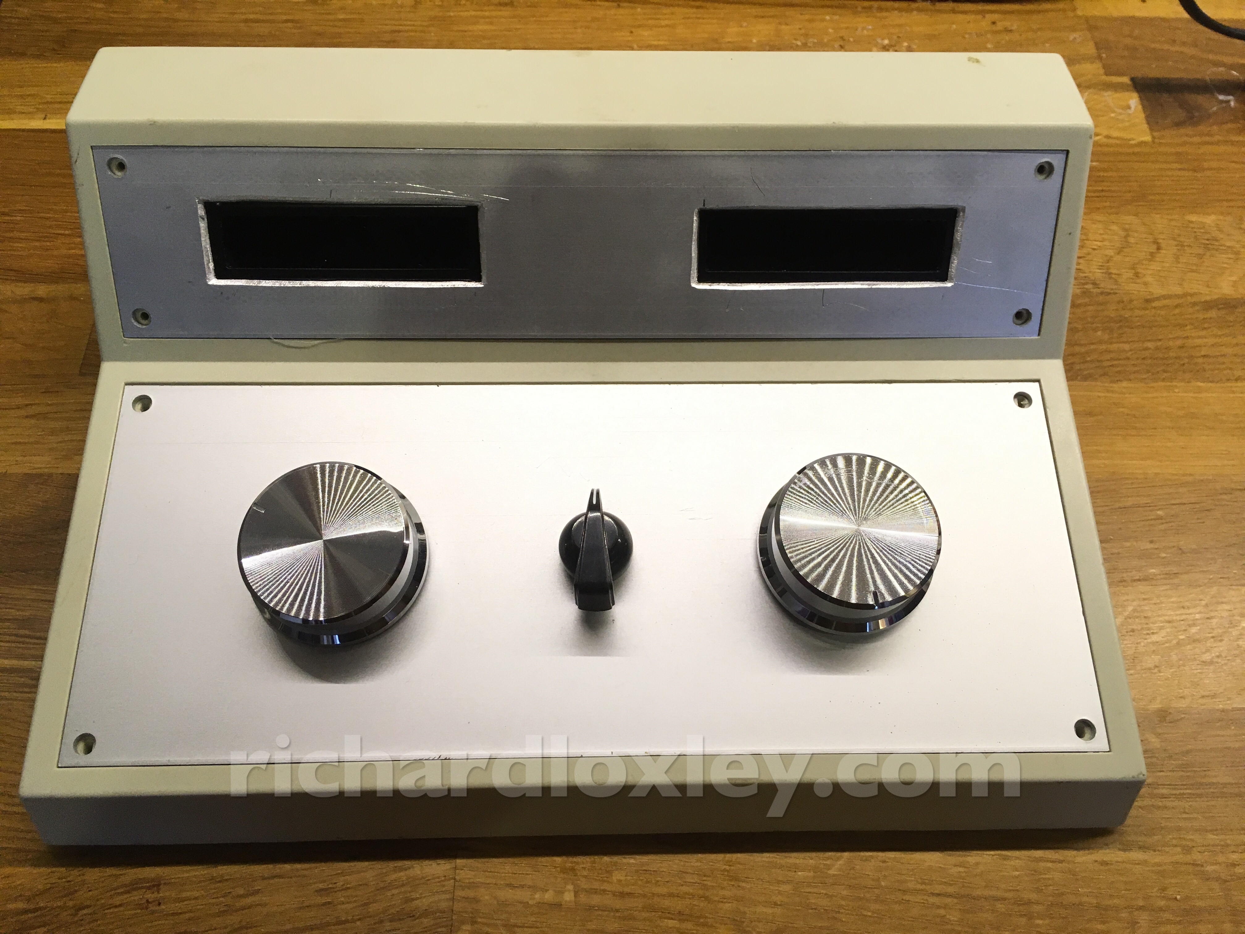
Hot glue! And lots of it. Those LCD displays aren’t going anywhere.
It’s beginning to look like the original design!
Now to extend all the ribbon cables from the breadboard into the case:
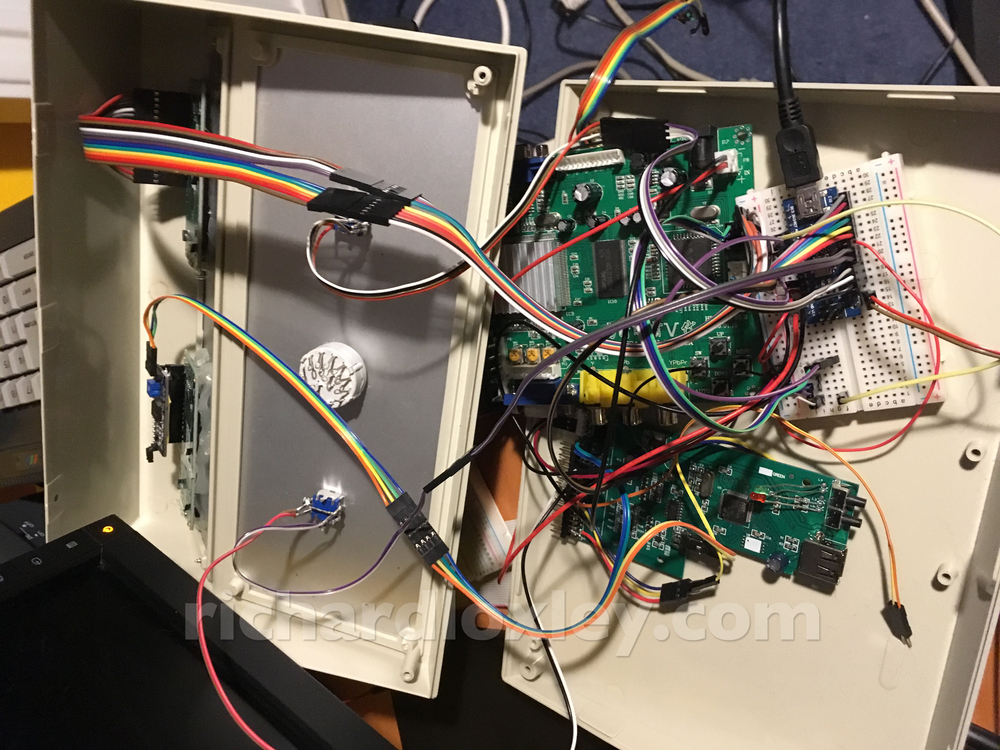
And turning it on – it’s looking just as awesome as how I imagined ![]()
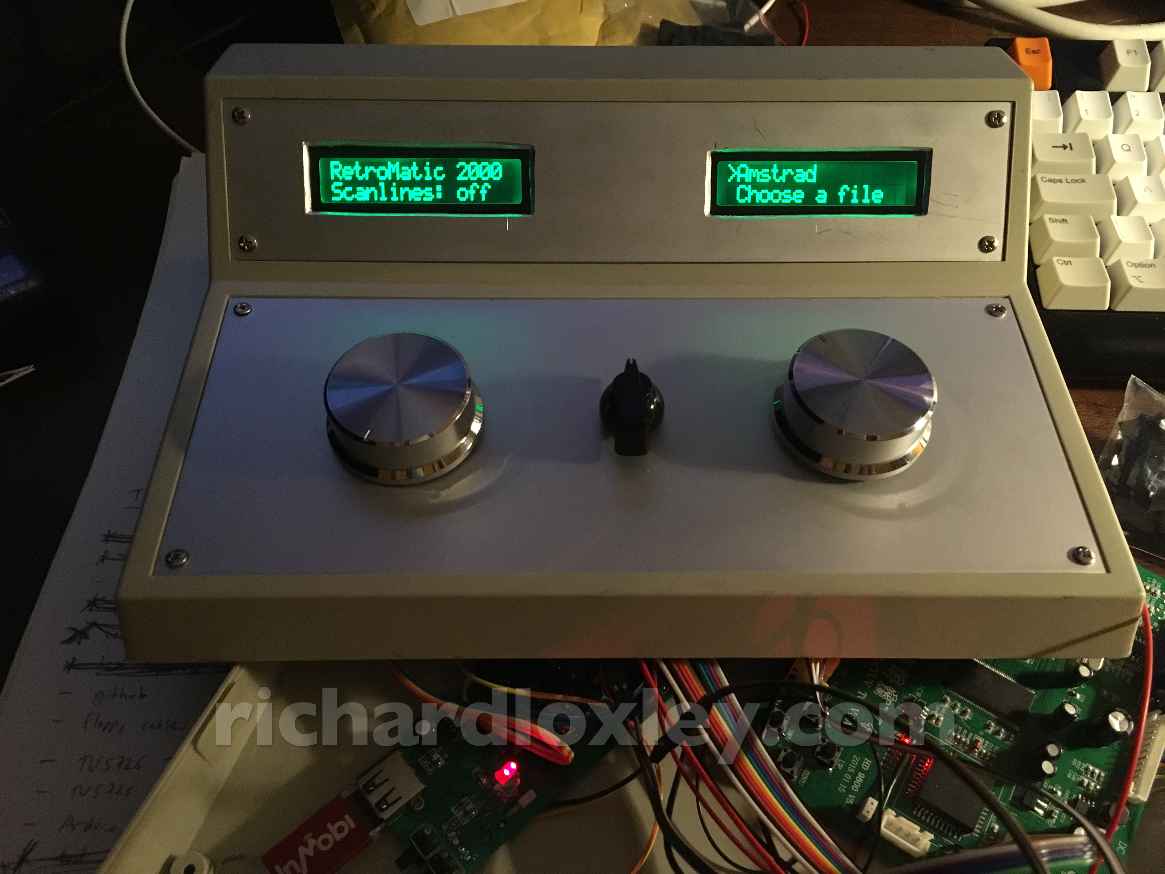
The two large knobs work to control the menus on the respective displays. (I’ve only got a simple place-holder menu on the left hand display for now.)
The drive select knob in the middle does nothing so far (I just need to solder some wires onto it and then they connect to headers on the floppy emulator).
The USB stick is internal for now (the USB socket hasn’t arrived yet from China). I’m probably going to put that on the top.
Now to revisit the circuit board and get soldering! I’d really like to get everything off the breadboard and soldered up properly before the end of the Retro Challenge. It’s going to be tight though…