After drawing a (dotted) line under my entry for the Retro Challenge, I took a week off from the project to have a rest.
For the Challenge I was able to demonstrate pretty much everything, but it wasn’t very reliable, and bits were breaking and being repaired in between shots of my wrap-up video!
So time to revisit it, and get it up to scratch to be a usable product.
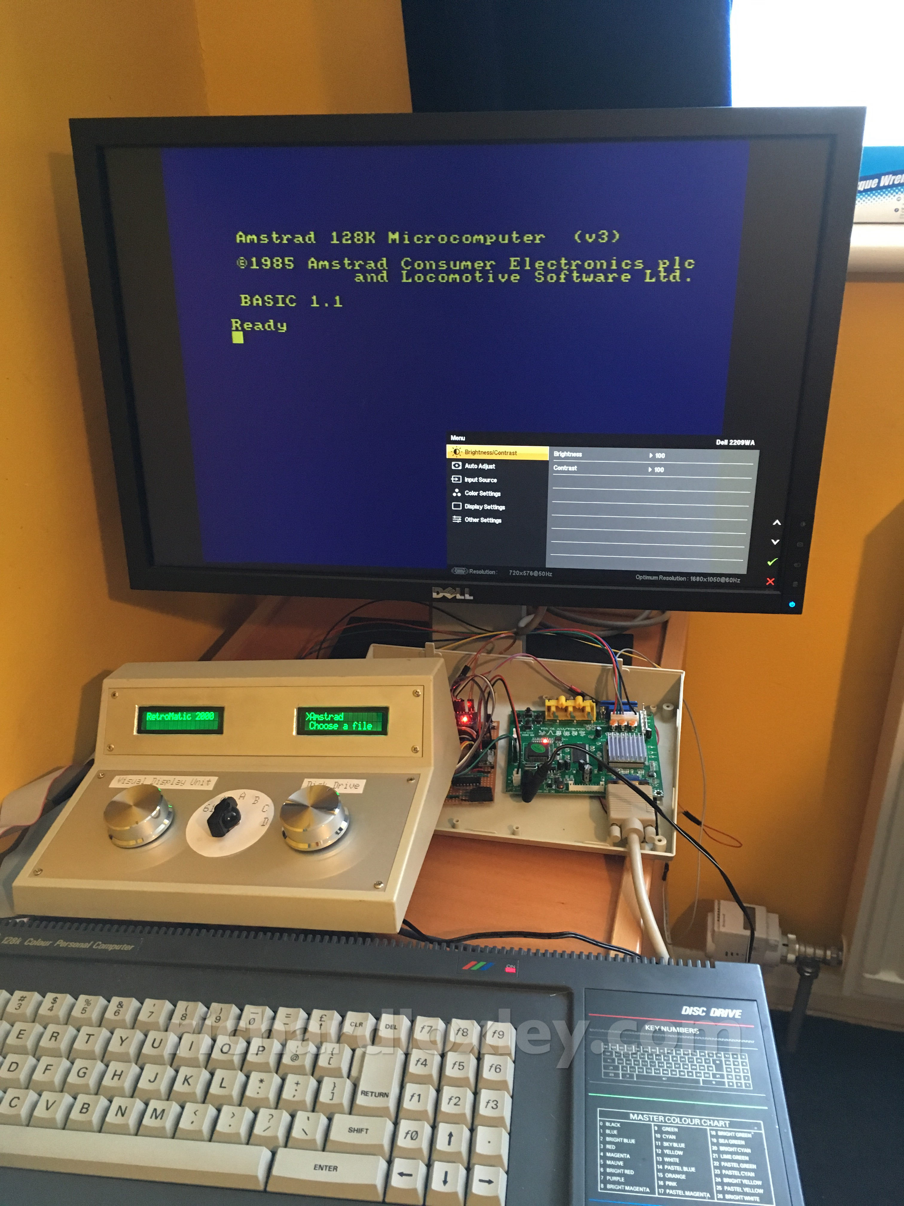
First off, when I recorded the video for the Retro Challenge my homemade SCART cable broke. It had taken me several hours of swearing to make it in the first place, and I had said never again. So I decided to buy a pre-made one to replace it.
This one has a 5v feed from the Amstrad to activate SCART RGB switching, allowing it to work with modern TVs (to some extent at least).
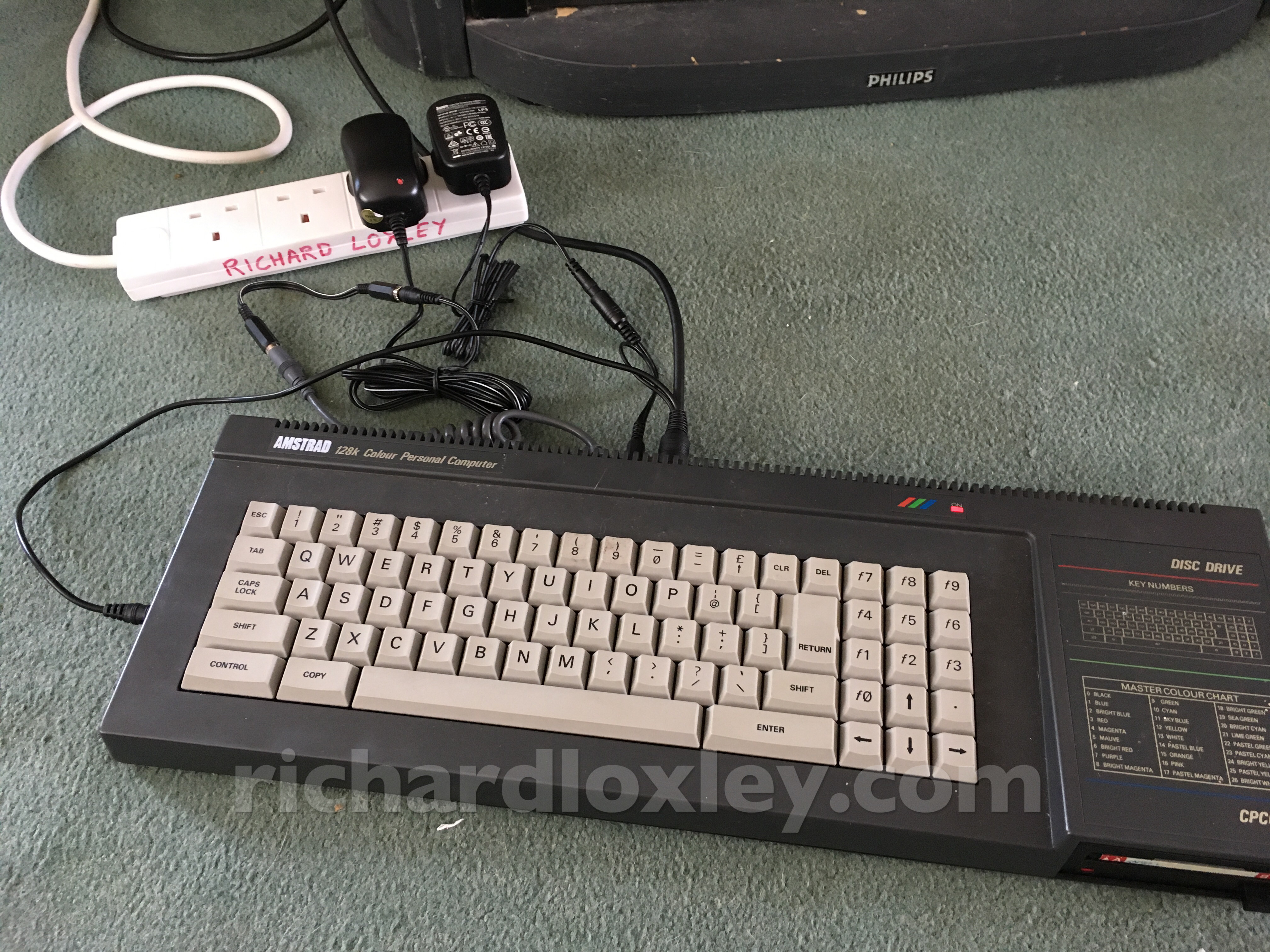
The seller also did bundles with 5v and 12v power supplies to run the Amstrad and disk drive without needing the Amstrad monitor. I’d been intending to make something myself, but the price was tempting enough to just get the bundle ![]()
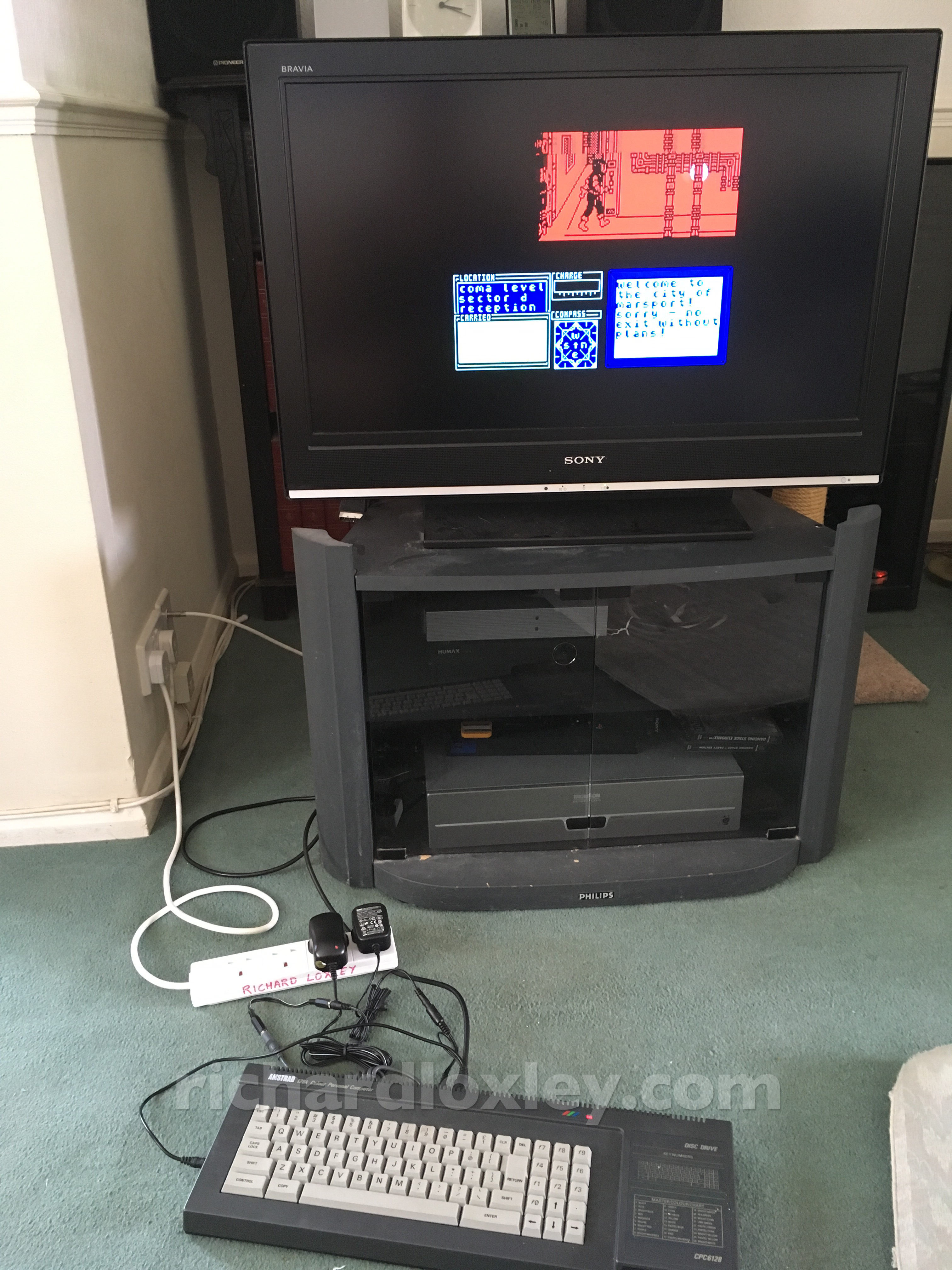
This SCART lead will work with my TV. Sideways scrolling (seen here in Marsport) isn’t too bad despite trying to deinterlace a non-interlaced signal.
It doesn’t negate my RetroMatic 2000 project, as I still want to use it with a desktop monitor rather than squatting in front of the telly!
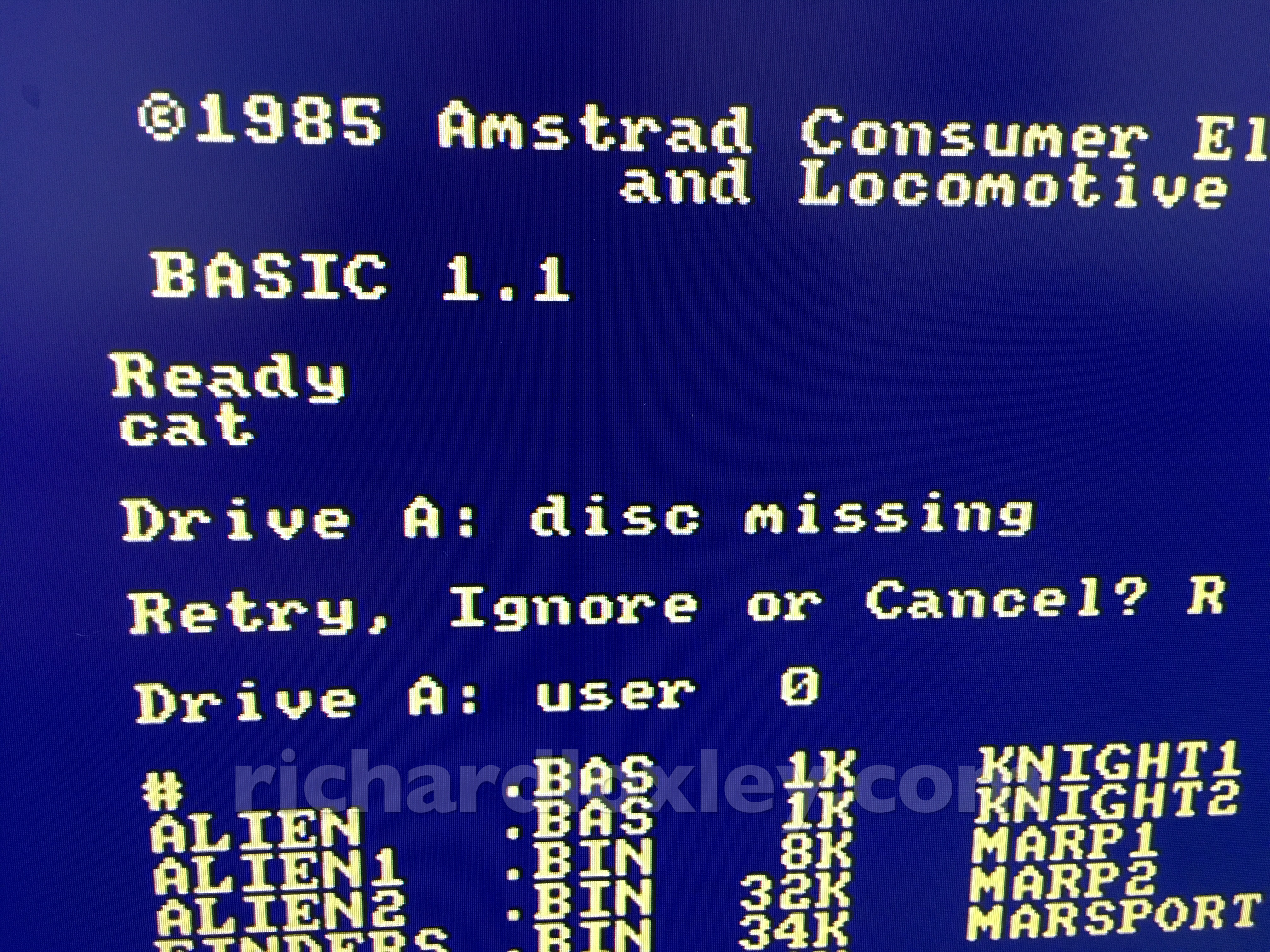
A fairly crisp picture close up on the telly. No scan lines though ![]()
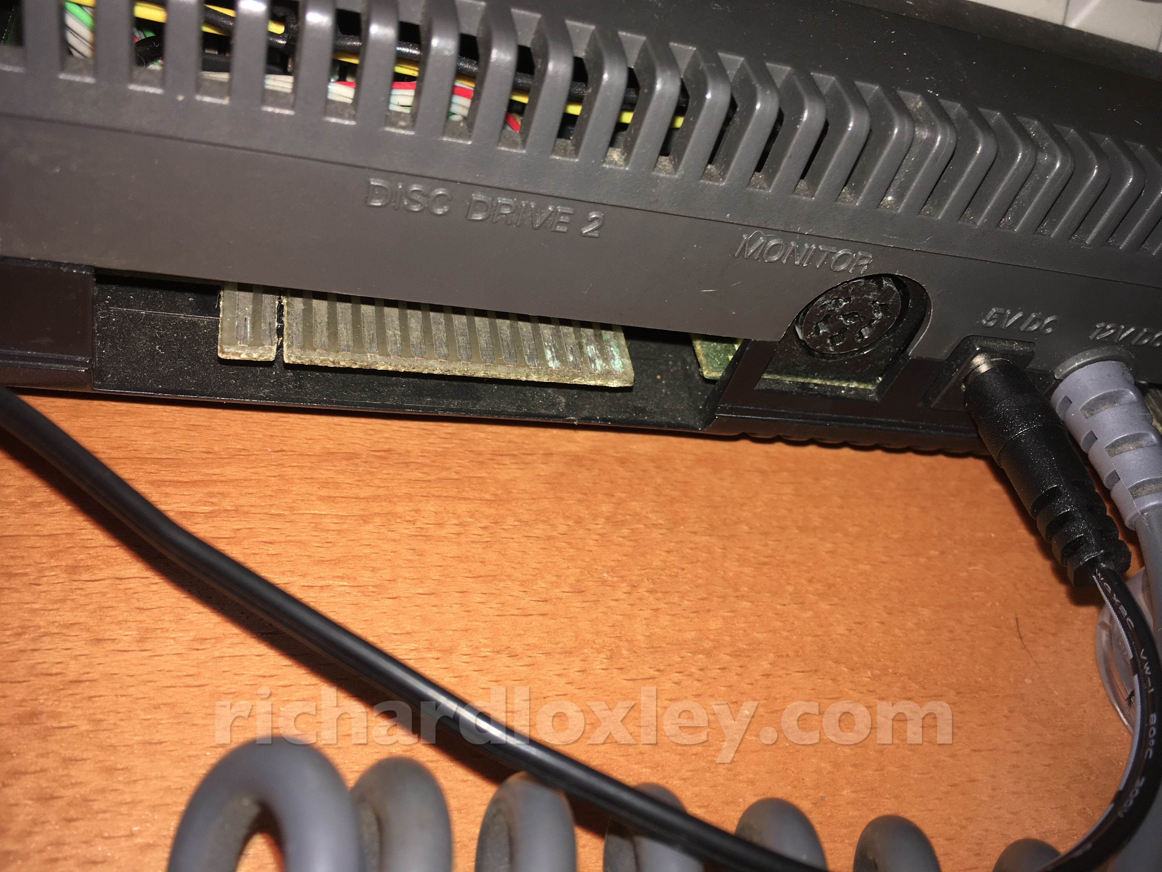
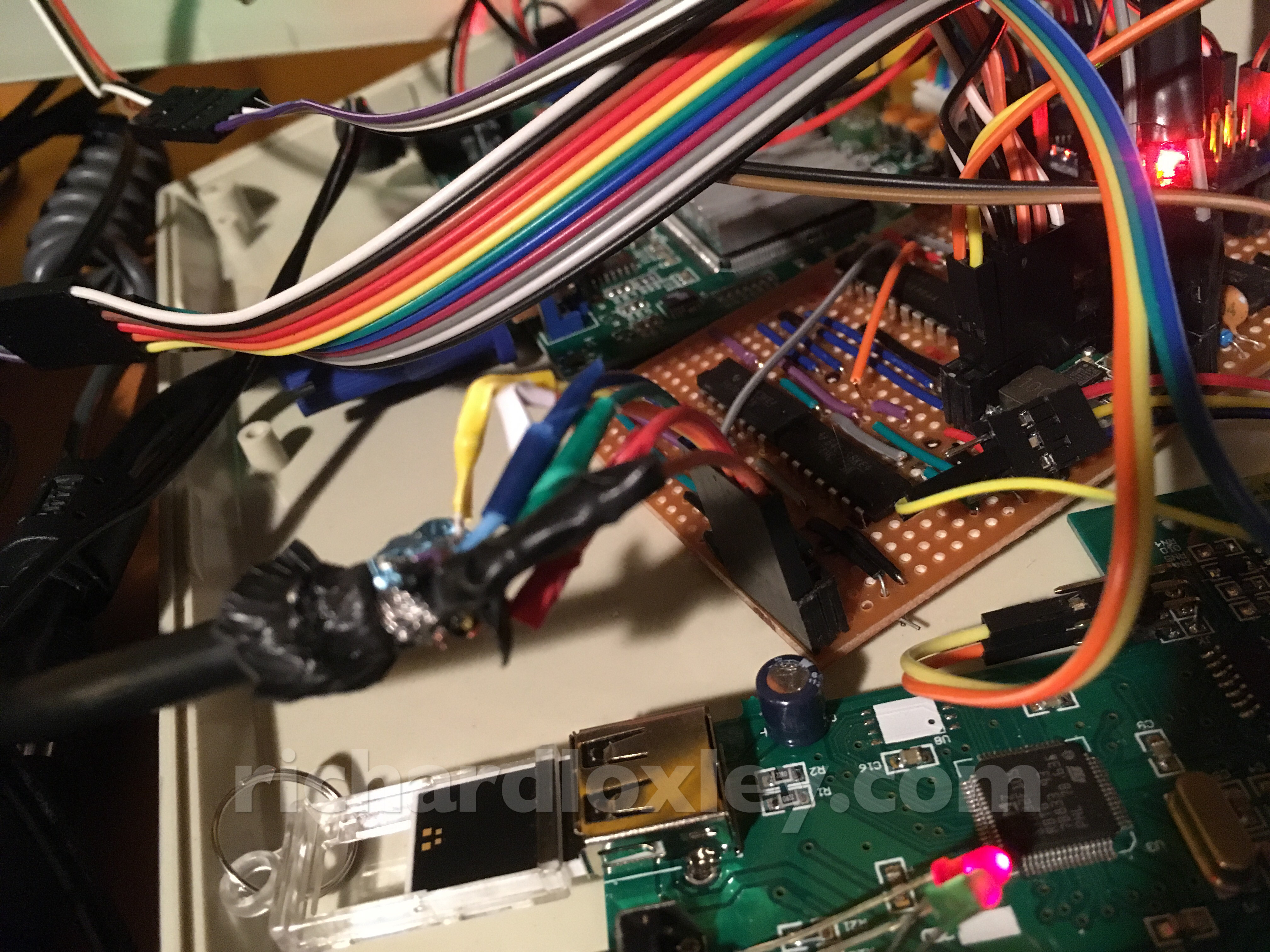
Next, I was having some disk read errors with my RetroMatic 2000 USB disk. I wonder if this crusty edge connector has anything to do with it? I cleaned it with alcohol on a cotton bud before reassembling my test bed configuration.
I’d always suspected my lovely circuit board might need some ‘on the fly’ modifications – and I was correct.
Today I learned something new about integrated circuits – they don’t stop working just because you turn the power off! ![]()
I have a switch to turn off the power to the two ICs that form my scanline generator. But you turn the power off, and the scanline generator carries on working!
Apparently it’s because the logic inputs still have some voltage going to them. The ICs have protection against the logic inputs being a higher voltage than the supply voltage, and drain the excess voltage using ‘protection diodes’. So if you have no supply voltage, all that voltage on the input pins is drained through the chip’s power lines, which then ends up powering it!
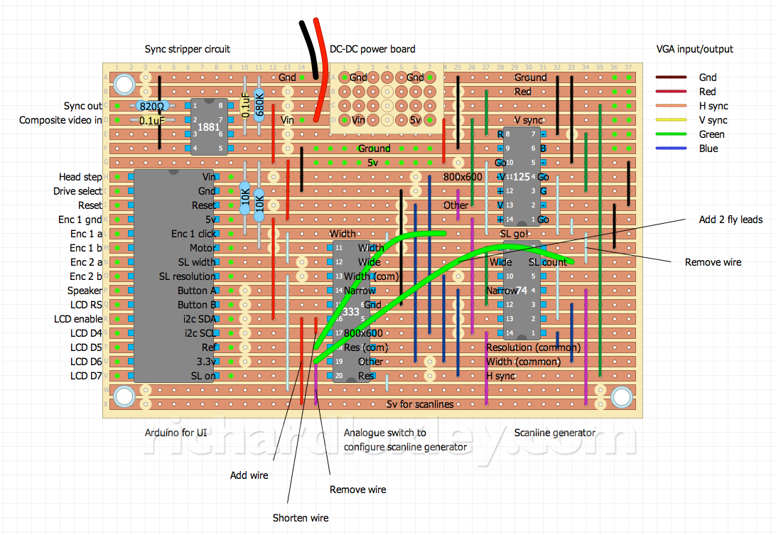
So here’s my modified circuit which should hopefully fix it. Instead of powering off the two chips, I’m going to leave them permanently powered. Then I’m going to redirect the “go” signal from the scanline generator through the switch instead. So that logic signal will either get through to the chip that blanks the scanlines, or it will be connected to 5v (indicating no scanline). I’ve tested the theory by cutting the “go” line, connecting the end of it to 5v, and leaving the chips powered. That does seem to disable the scanlines.
The new Amstrad power supplies mean I don’t need to balance two monitors on this pedestal unit! A much neater test area now.
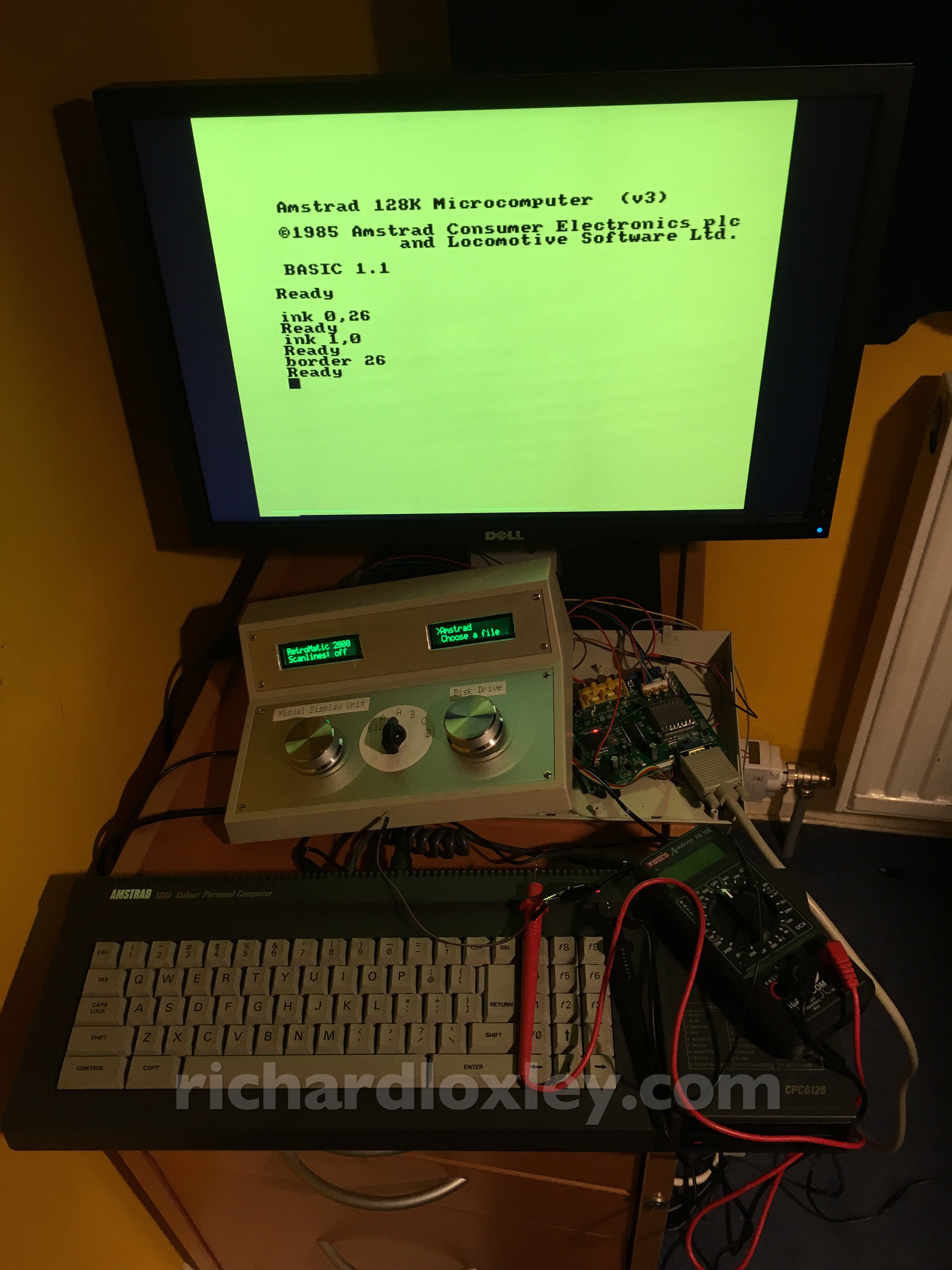
My reworking of the circuit board means that the scan lines can be turned on and off by the menus now :-)
I was having some bad interference issues, but on checking I found the Arduino voltage was only about 4v. I guess the 6v input wasn’t sufficient for the voltage regulator. I’ve upped it to 12v and now the Arduino is running at 5v and no big glitches.
I’m still finding the double-width scan lines don’t work reliably (the same happened when I ran it on the breadboard). That needs more investigation.
But the most obvious thing here is the colour – that should be a white screen! The blue signal isn’t getting through.
I’ve tested the SCART signal, and the blue is getting as far as the HD9800, but isn’t coming out of the VGA output of the same board. I’ve disconnected the Arduino and used the built-in software, and it runs the same. Faulty HD9800 board? It wouldn’t be the first fault! I do have another on the way from China…
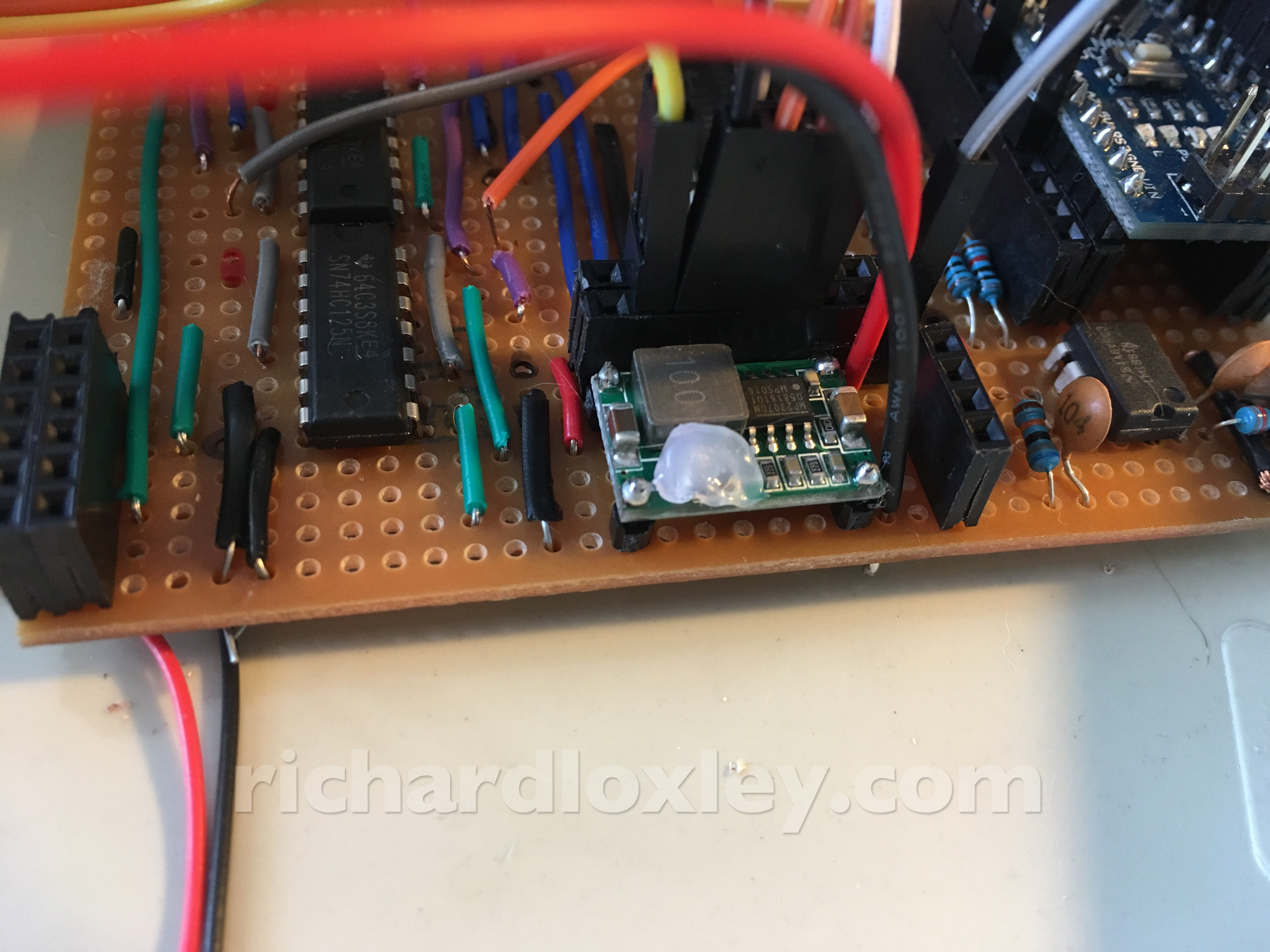
Another day, and another delivery. Here I am testing this tiny DC-DC converter board before putting it in the RetroMatic 2000.
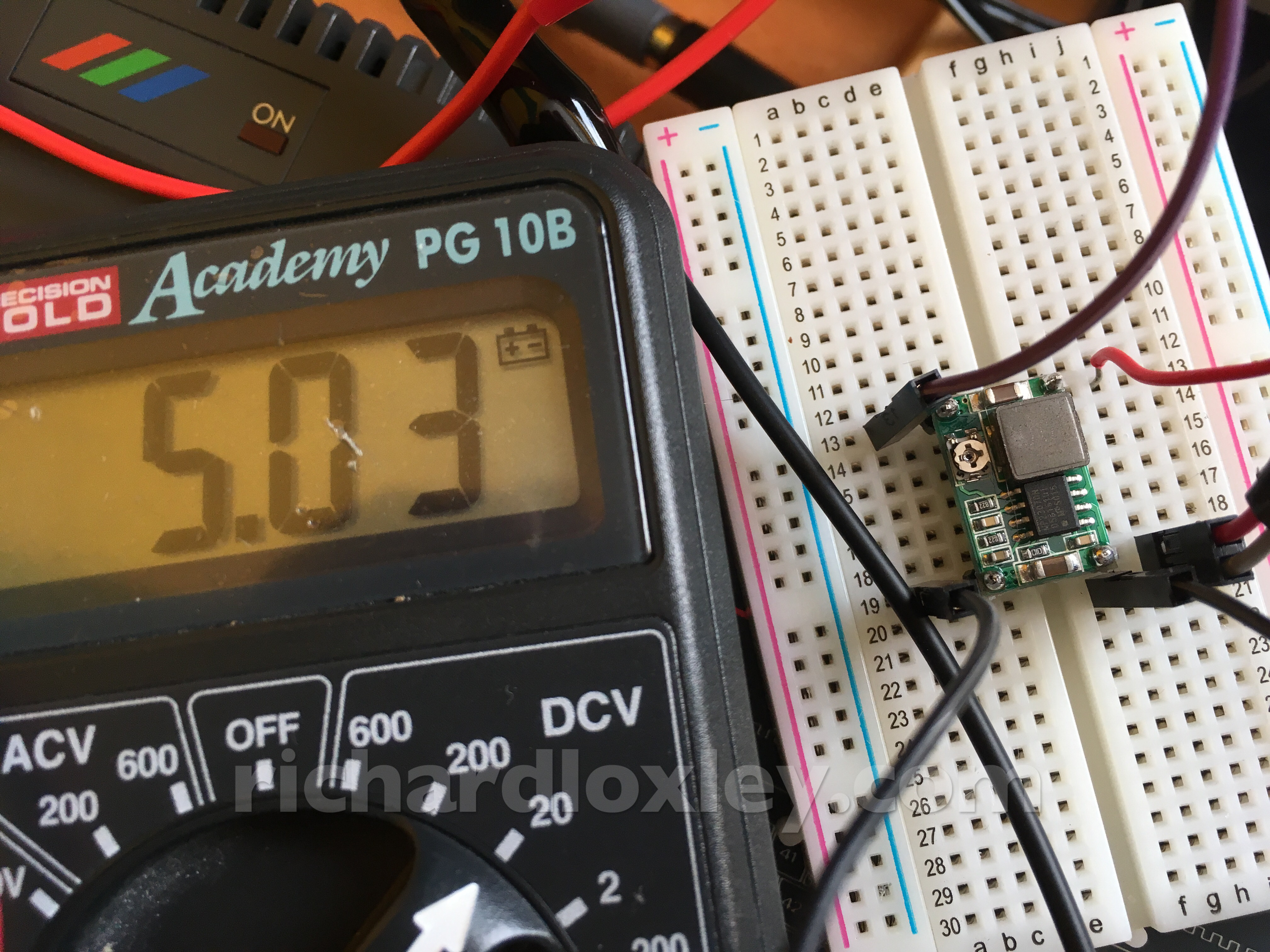
It’s got adjustable voltage output, and the pot is very sensitive! After a minute or two adjustment this was as close as I could get to 5v. Should be good enough, but I think I’ll put a blob of hot glue over the pot to stop it moving!
How much for this beauty? 25p! You couldn’t buy the components for that! (£2.46 for ten boards including postage from China.)
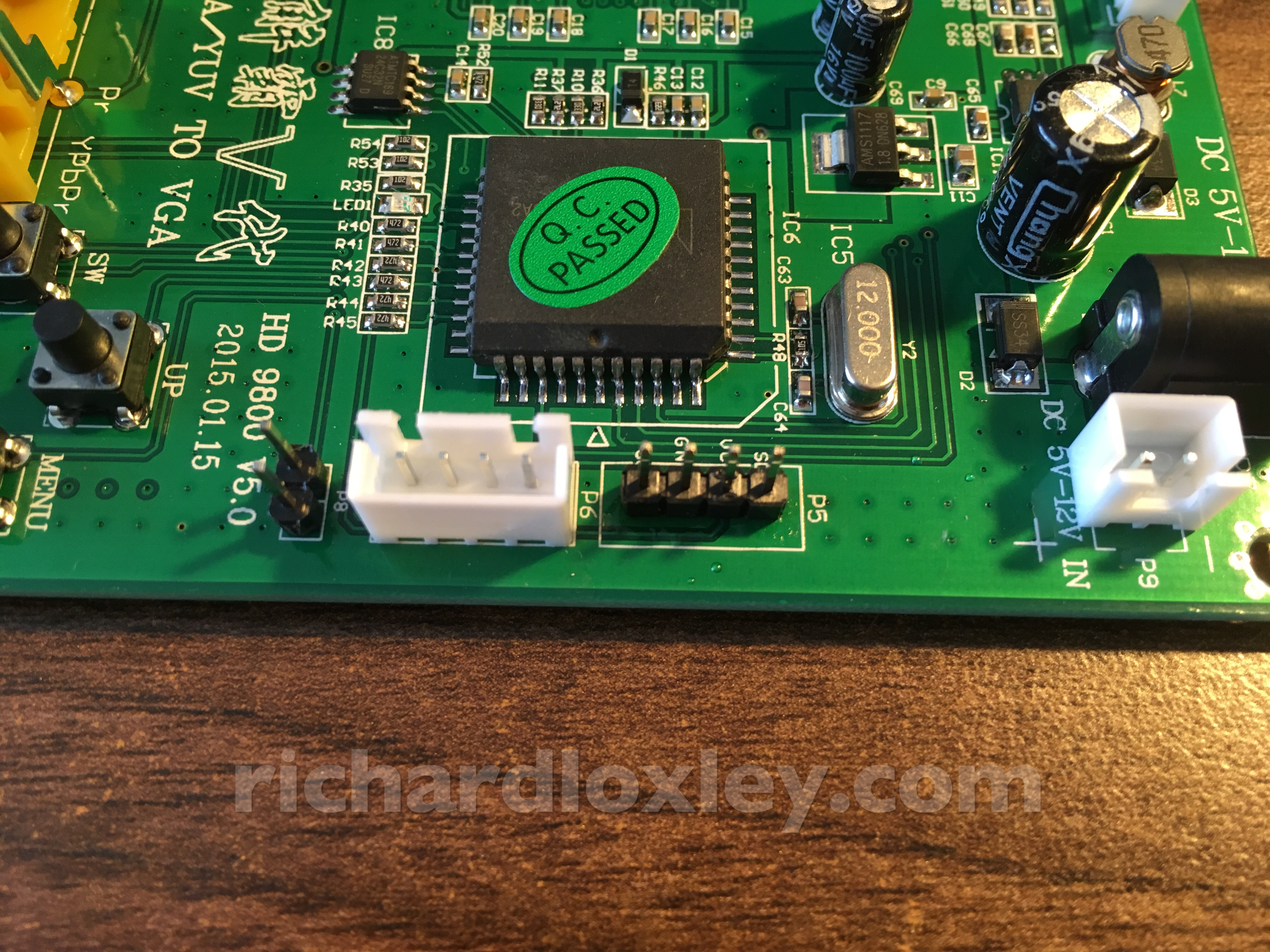
And today more deliveries. My replacement HD9800 to hopefully fix all the niggling issues on my damaged original one. Soldering on the i2c headers went much more smoothly this time!
I’ve also installed the DC-DC power board on my main circuit board (and glued down the voltage adjustment pot so it’s fixed at 5v).
And success, the new HD9800 works correctly (including blue!) and communicates with my board:
Next up: investigate why the double-width scan lines don’t work. This mode is supposed to blank out pairs of horizontal lines on the VGA output, rather than just every other line. The idea is eventually I’ll run the HD9800 video board in a higher resolution than 768×576 (because that isn’t a standard VGA resolution, so isn’t compatible with all monitors). But then I’ll need wider scanlines to match the higher resolution.
When I switch into wide mode, it sort of works, but I get loads of interference, with bands rolling up the screen. It looks like a loss of sync, or perhaps bad grounding.
My first thought was interference on the VGA output. I use a ribbon cable to get the signal to my scanline generator, rather than a decent cable. Also the old ribbon cable was soldered onto the old HD9800 board, so I needed to do something new with the new board.
So I decided to use the VGA socket on the HD9800 board, and cannibalise an old VGA cable:
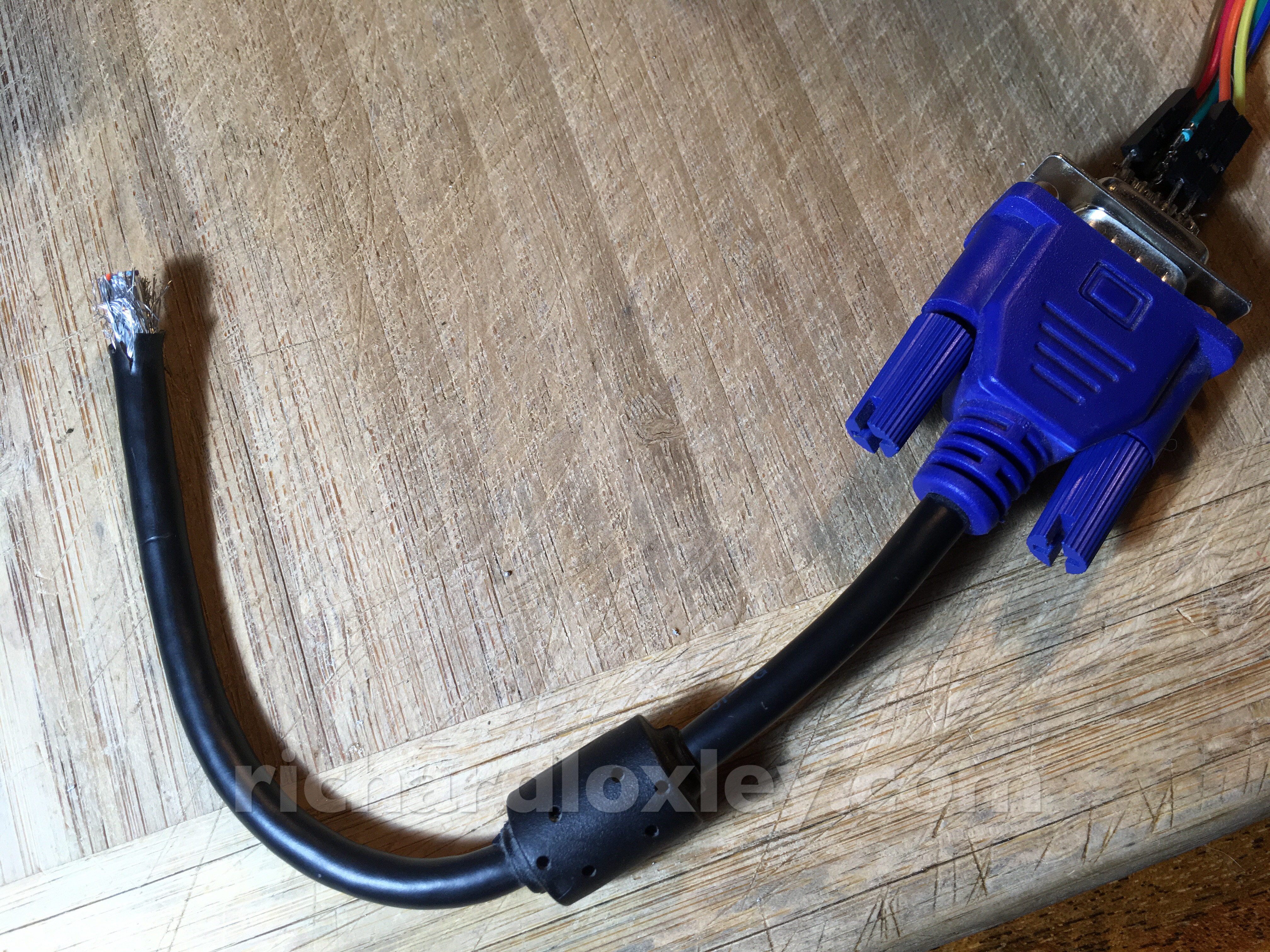
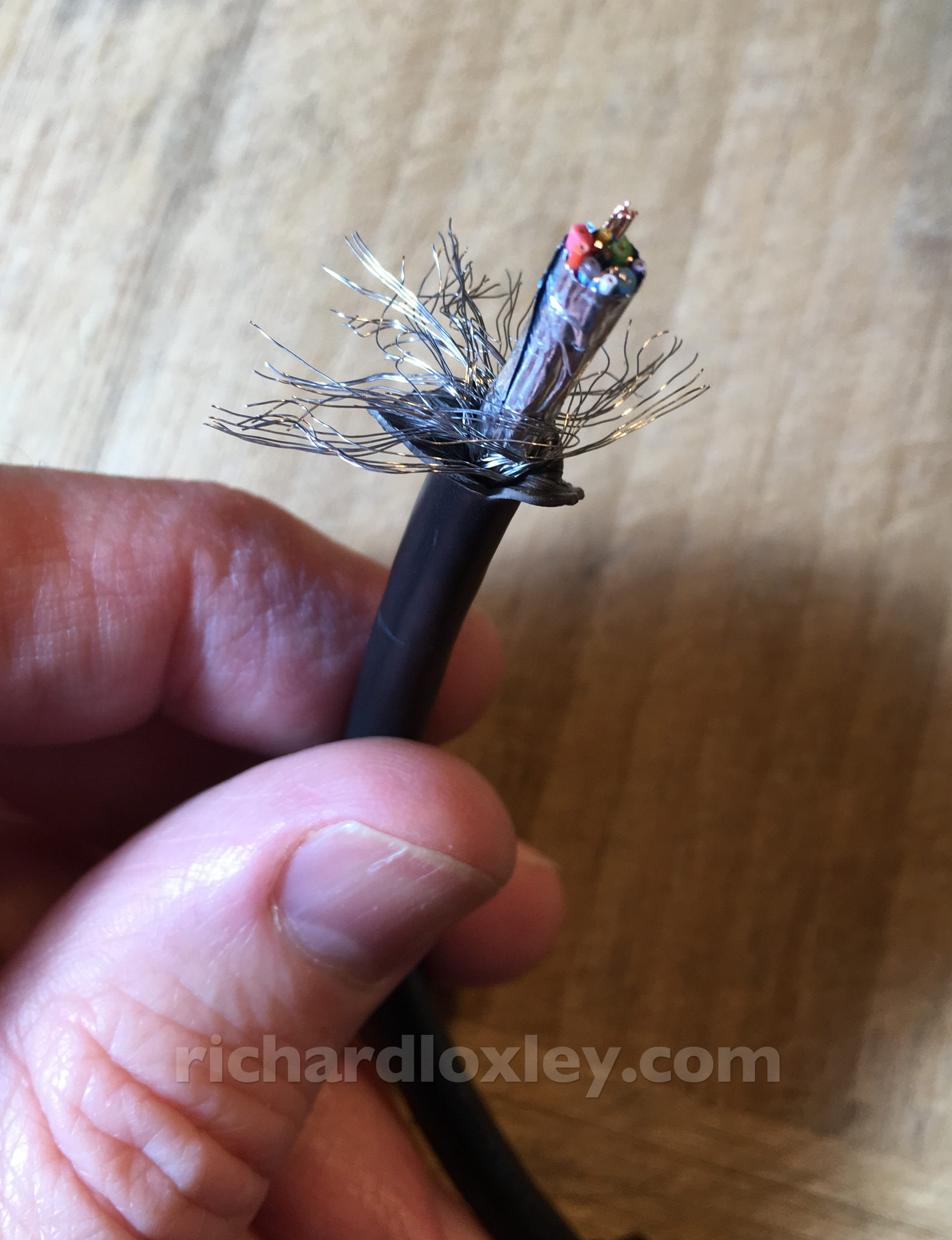
This cable is well shielded: a ferrite bead on the outside, then a grounded wire shield, then a foil shield round all the cables, then individual foil shields round each signal cable, then separate grounds for each signal cable inside that!
I tried to maintain the shielding as much as possible while I soldered on header connections at the other end. The result is a bit of a mess, but it will be hidden inside the case:
The picture is now more solid in general, but the wide scanlines still don’t work. Now to try making a shield for the ribbon cable that takes the VGA output from the scanline generator to the VGA output port:
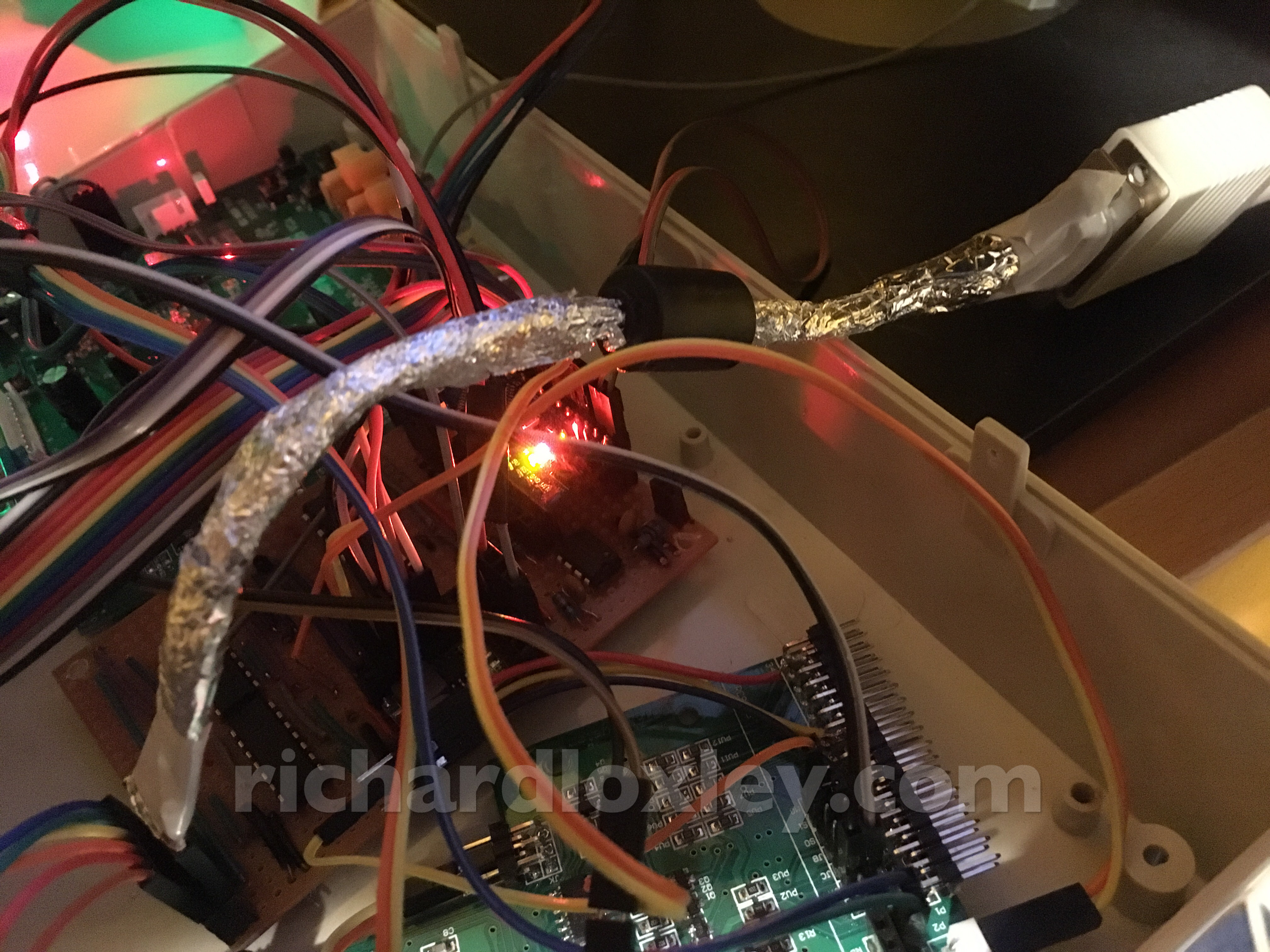
That thing that looks like a prop from Blake’s 7 is the VGA ribbon cable covered in kitchen foil (grounded at one end) and with the spare ferrite bead from the other end of the cannibalised VGA cable over the top.
But still no joy with the wide scanlines!
So I’m now beginning to doubt the circuit that I used to make this. I used the mmmonkey circuit as the basis for this. I checked and double checked I used his circuit correctly.
The development for the circuit came from a 14-page forum discussion with many hundreds of posts. I spent an hour or two wading through it, trying to understand the development, and looking for any photos of boards that people had made, to try to spot the error. Hard when the discussion is 6 years old, and many linked photos had since disappeared!
Eventually I found this post, the only one where someone else has drawn out the actual circuit. And it was different! I’ve reproduced it here in case this one also disappears!
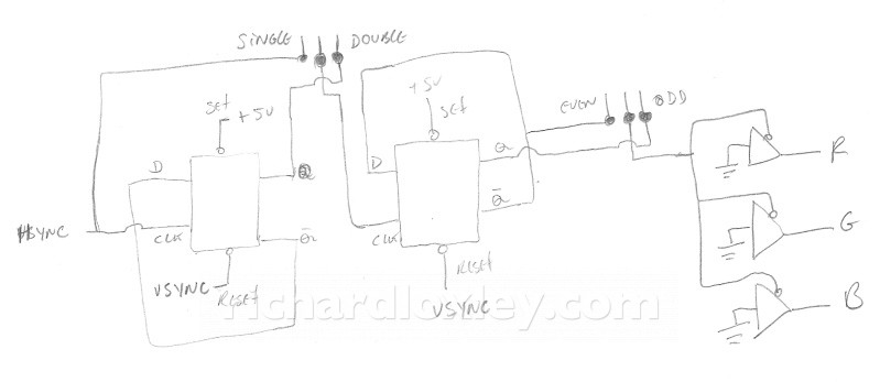
This diagram was the first that really makes clear how the circuit works. It has two flip-flop circuits as counters that count horizontal lines, and are reset when the vertical sync indicates a new frame. For standard scanlines the first counter is ignored, and the second counter blanks the scanlines. For wide scanlines the second counter is fed from the output of the first counter, so it counts in pairs of scanlines instead of singles.
Now the difference in this circuit is in the ‘set’ and ‘reset’ pins on the flip-flops. These override the count, and either set or reset the binary counter rather than toggling it. The “set” pins are held at 5v so it doesn’t activate (low voltage activates the line). The “reset” pin is connected to the vertical sync so we always start the count at 0 at the beginning of a new frame. (That’s probably only necessary if the number of lines in the frame aren’t a multiple of four.)
But in mmmonkey’s circuit, he doesn’t connect the ‘set’ or ‘reset’ pins on the second flip-flop!
I’m guessing that maybe it worked for him because he was lucky and the floating voltage on those pins didn’t trigger the flip-flop on his chip. But you can’t rely on it, and it certainly was triggering randomly on mine!
I tested connecting the reset pin to the vertical sync, and the set pin to 5v, and it looked like it was going to work! (As far as I could tell with four wires held by hand onto the board whilst trying to also glance at the screen!)
Time to revise my circuit yet again! The yellow wires are the new ones:
And after soldering:
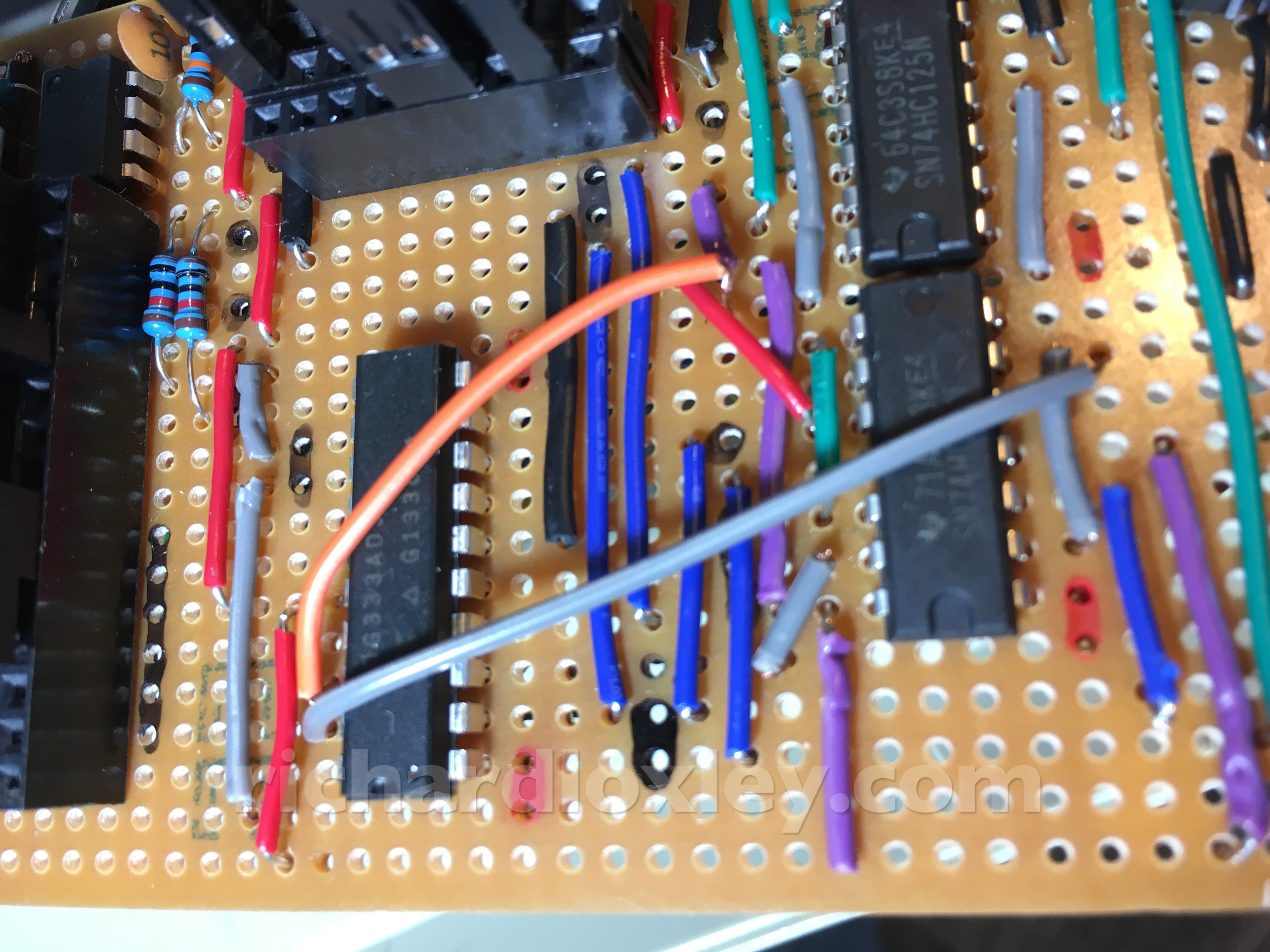
A bit messy, but I suppose it’s retro!
Time to power it up. Without scanlines it looks fine:
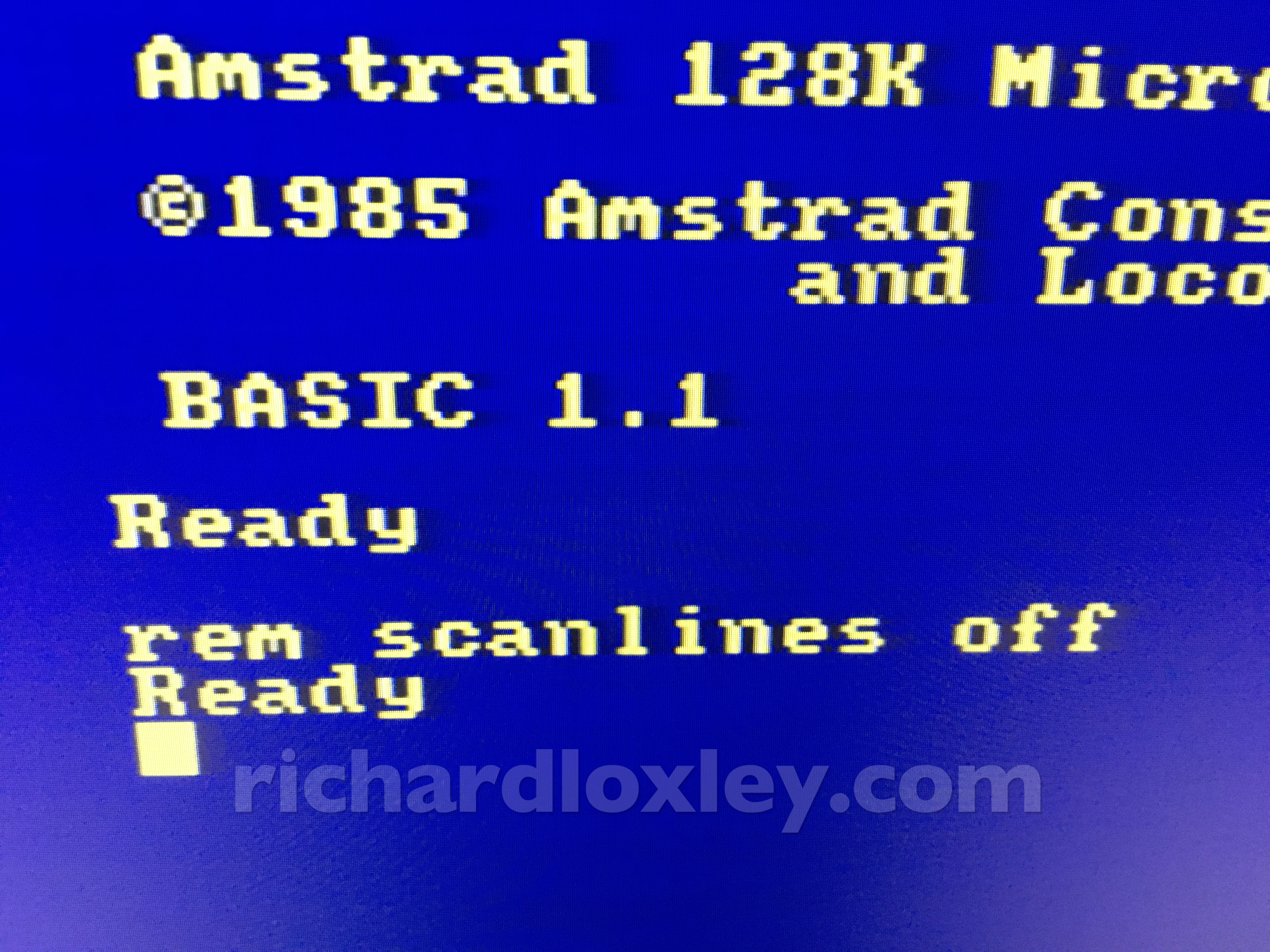
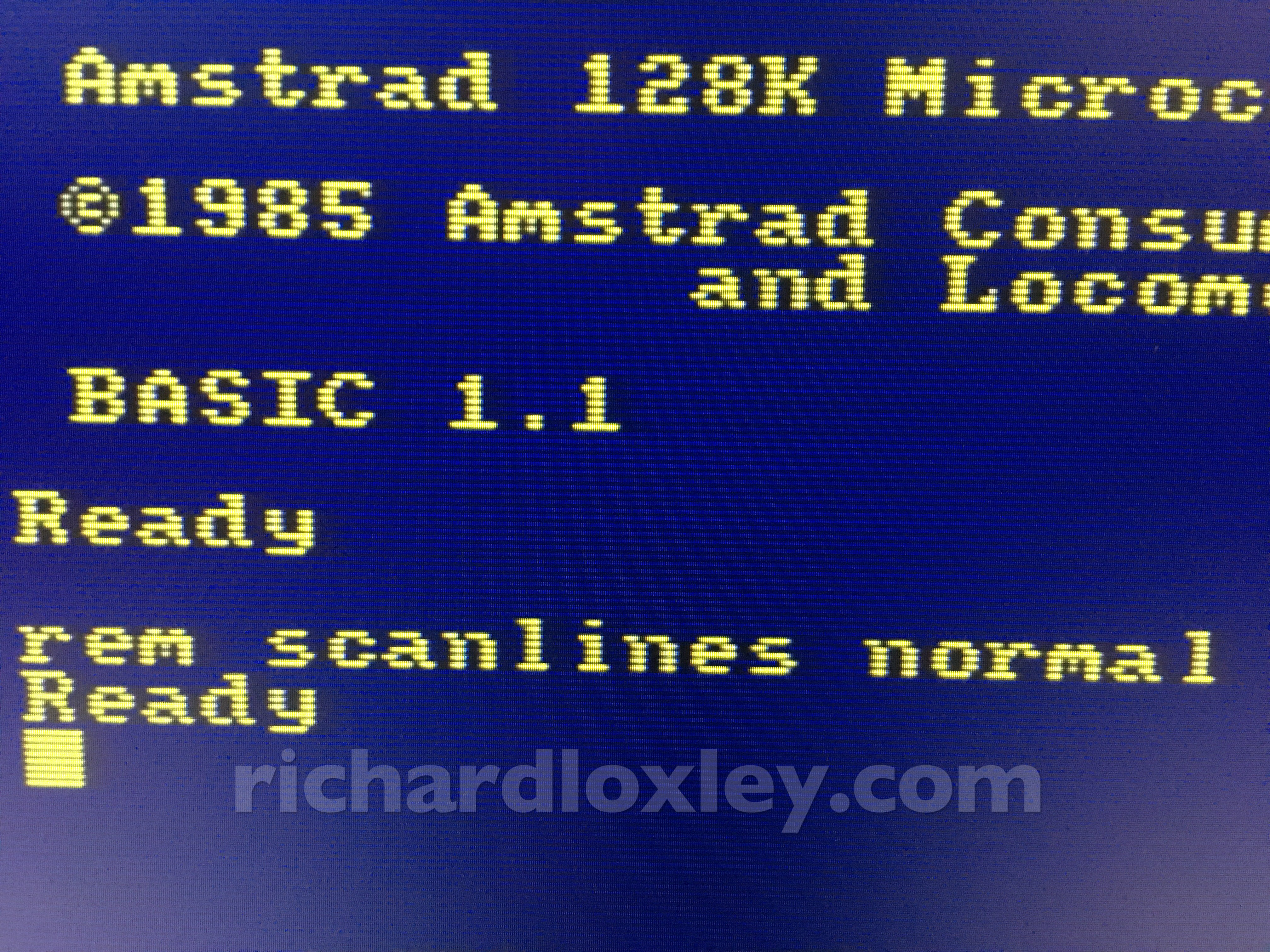
Normal (narrow) scanlines still work (and can be switched on and off in software):
And the moment of truth – will wide scanlines work?
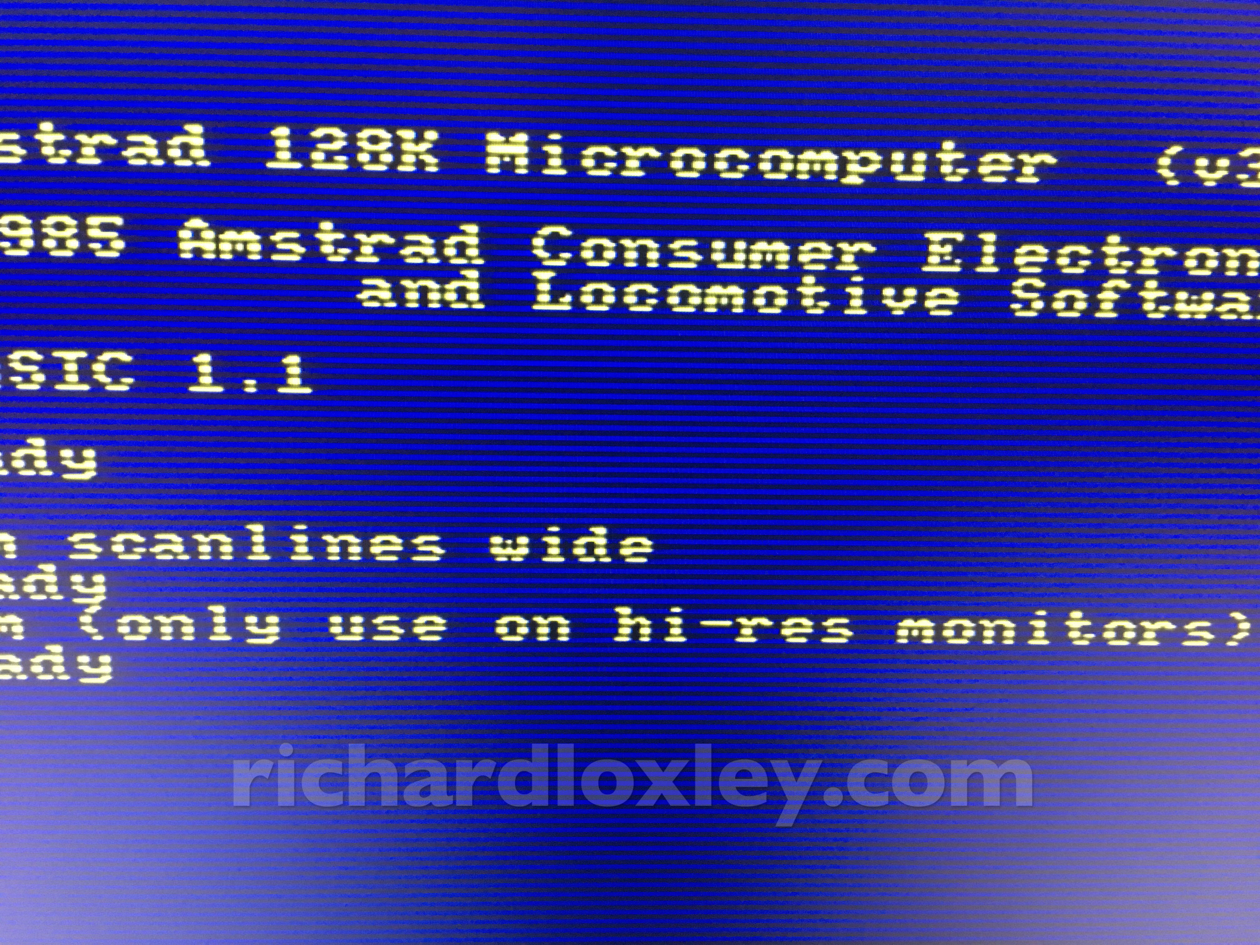
Yay! Finally!
I still need to do some work on the software controlling the HD9800 registers to get a high-res mode that actually needs the wide scanlines, but at least I now know it’s all working as designed.
Time for dinner and bed now :-)