Up until now all the components of my RetroMatic 2000 have just been loosely placed inside the case.
Well now all the bits I need to fix things down have started to arrive in the post, so time to start making things permanent!
First off, the video board, with holes for the YUV ports:
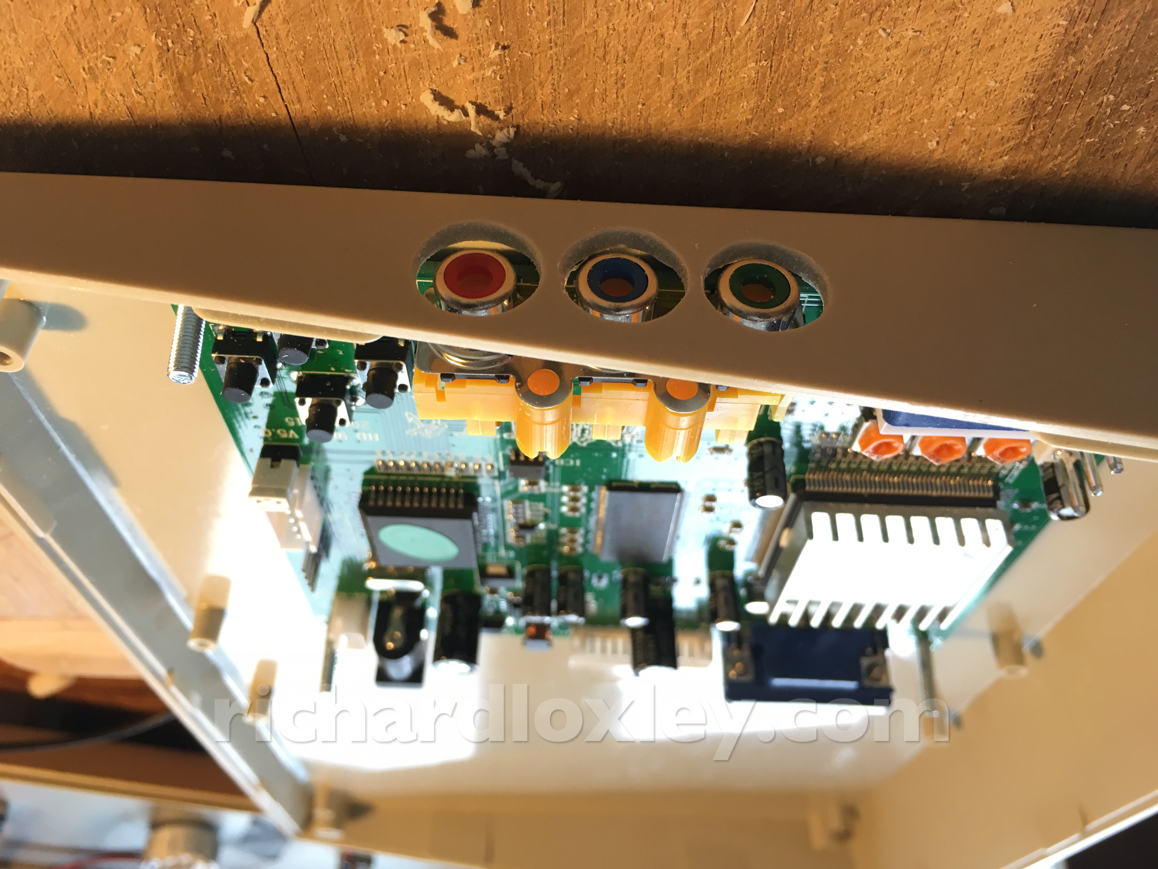
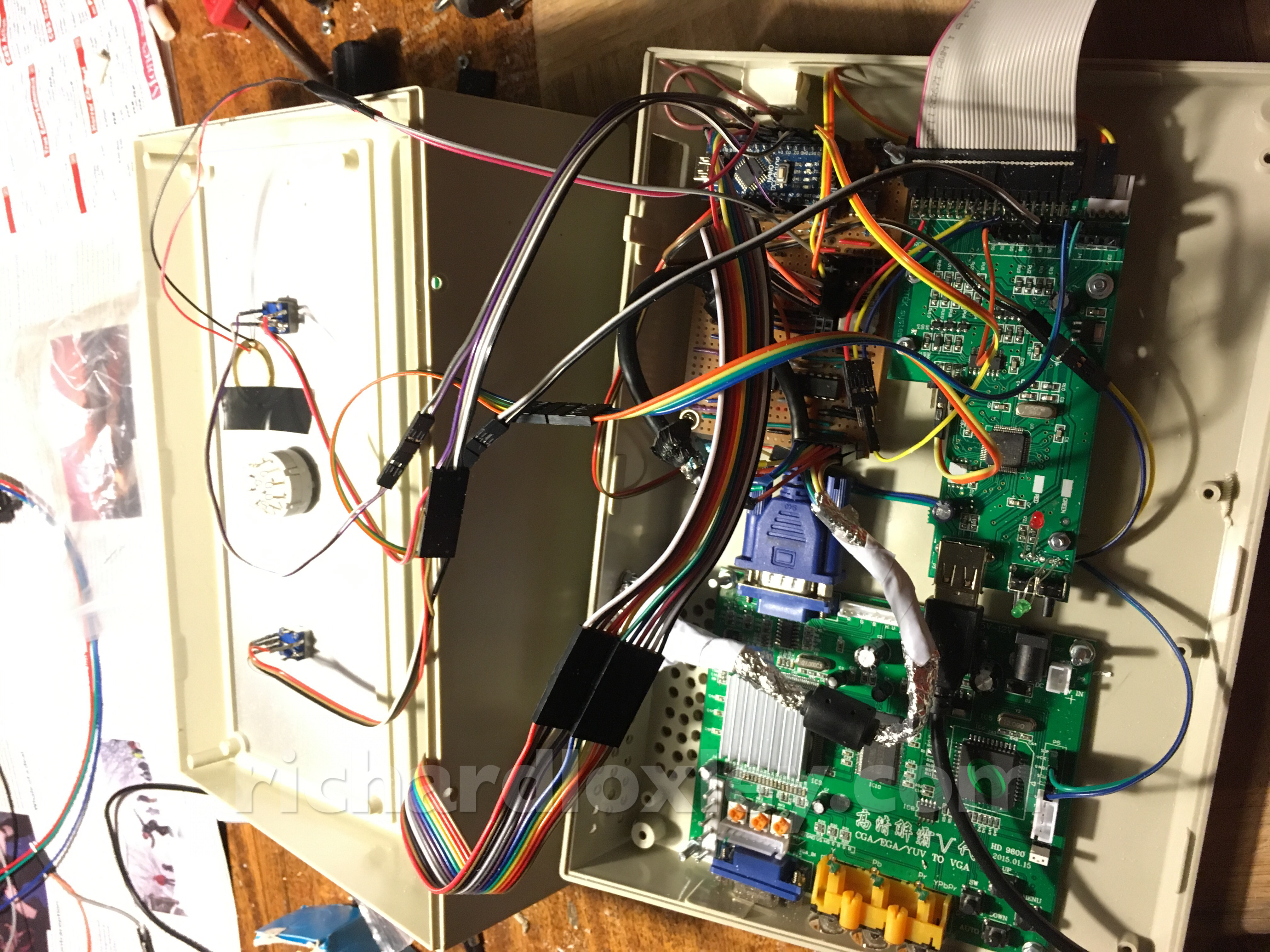
Figuring out where to put all the boards was hard. I thought I was going to have lots of room, but I decided to use the VGA port (blue connector) for the internal connection, and it’s so big that it really limits my options! Plus the floppy board has a USB cable coming out one end and a ribbon cable out the other end. The USB cable doesn’t bend sharply, so that board has to go along the long edge.
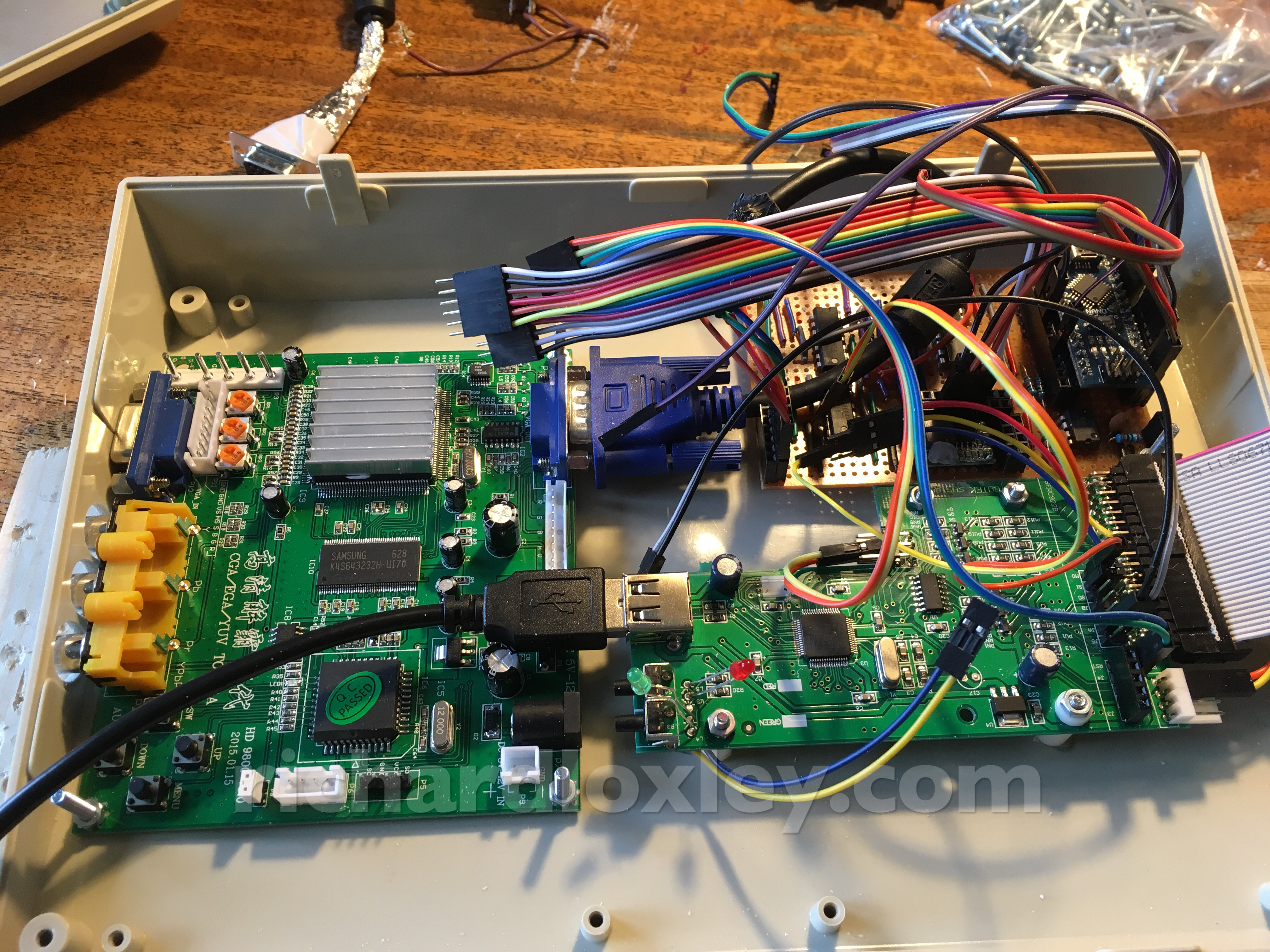
I managed to get them all in, but I needed to have them at slightly different levels so the cables cleared the components on the boards.
I ordered 15mm spacers, figuring longer was better than shorter.
But my 20mm bolts aren’t long enough by the time I’ve added in the thickness of the PCB and the case. Doh. But I can cut them down.
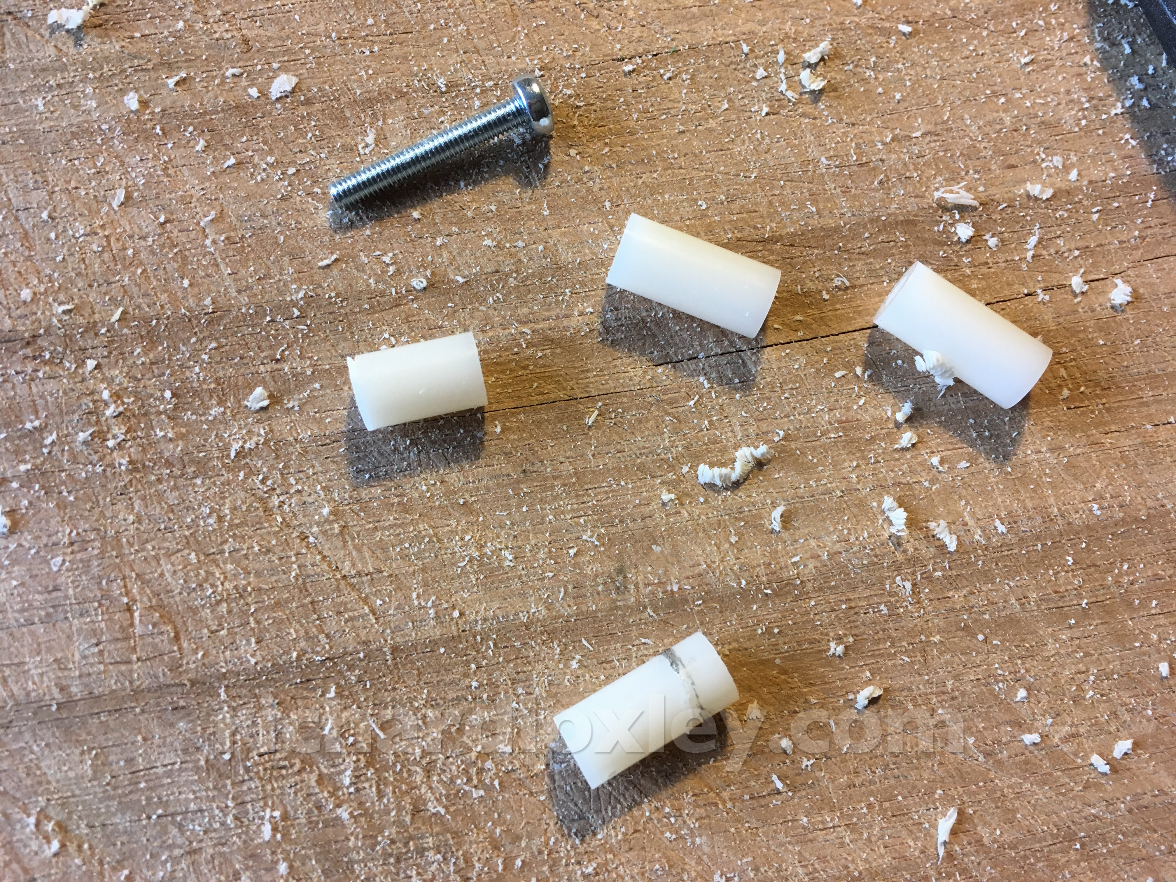
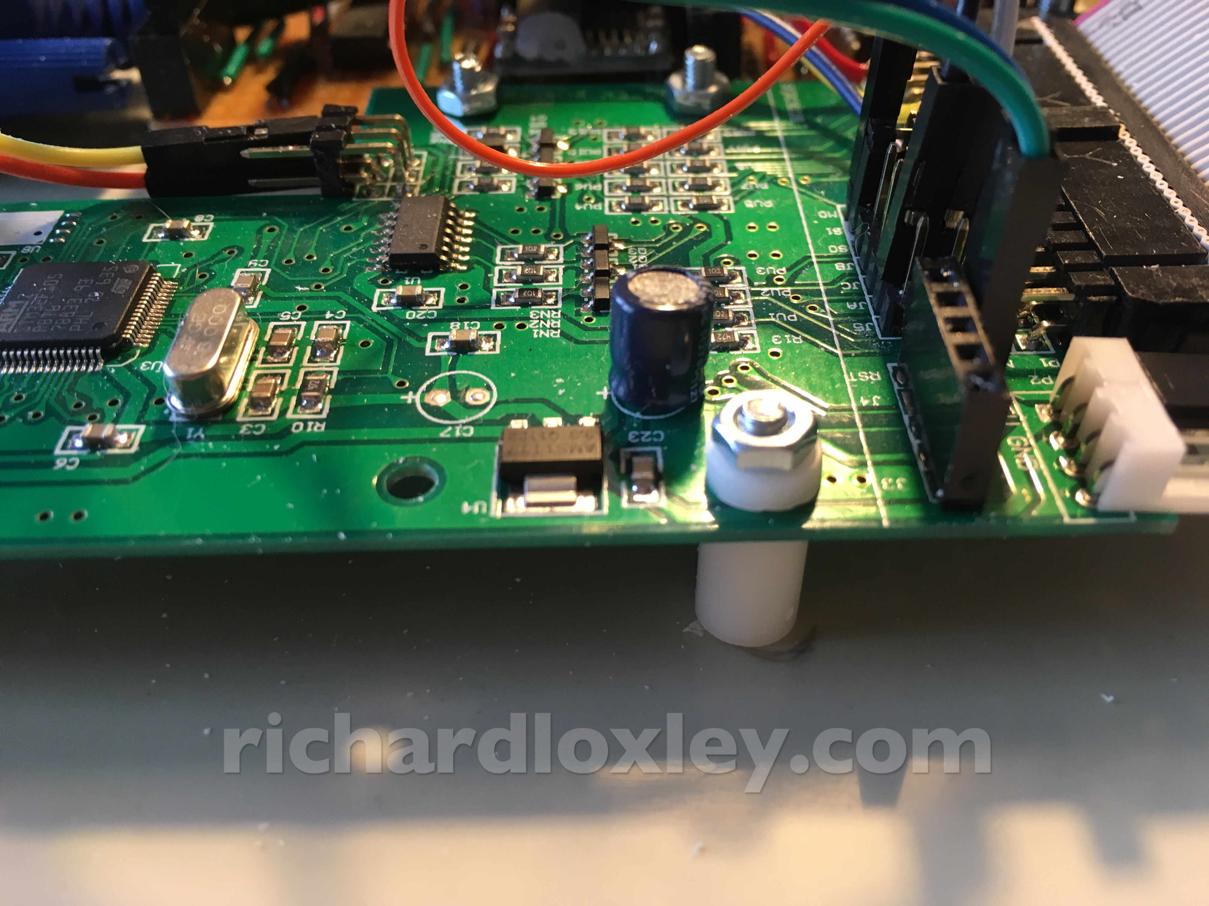
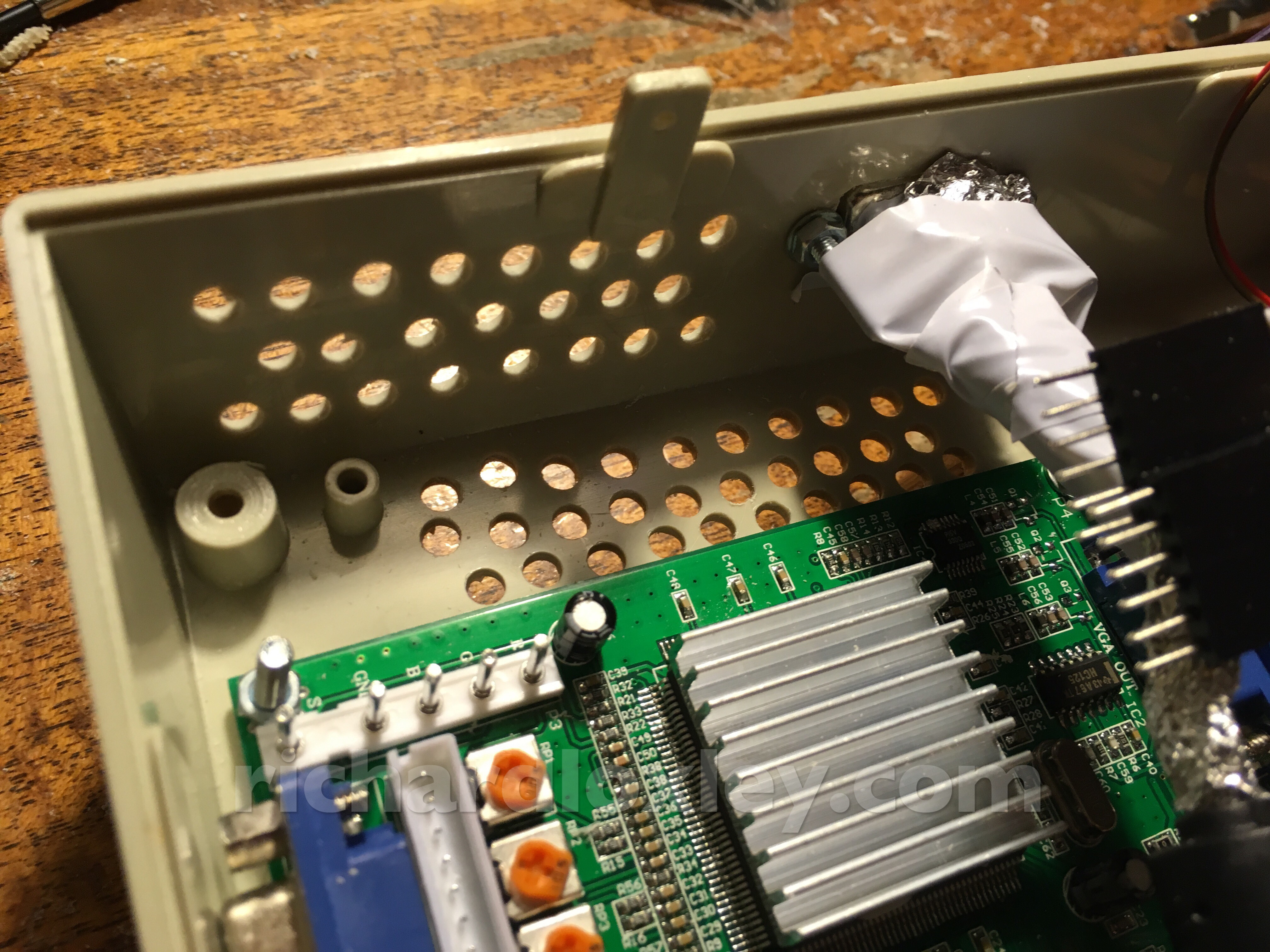
I made a plastic washer from the cut off portion of the spacer. All the holes are grounded, but on this board the nut would almost touch a 5v line too!
It doesn’t actually touch, and the PCB is coated, but I don’t want to take the risk!
Cutting a hole so I can access the USB port on the Arduino so I can reprogram it without taking it out of the case:
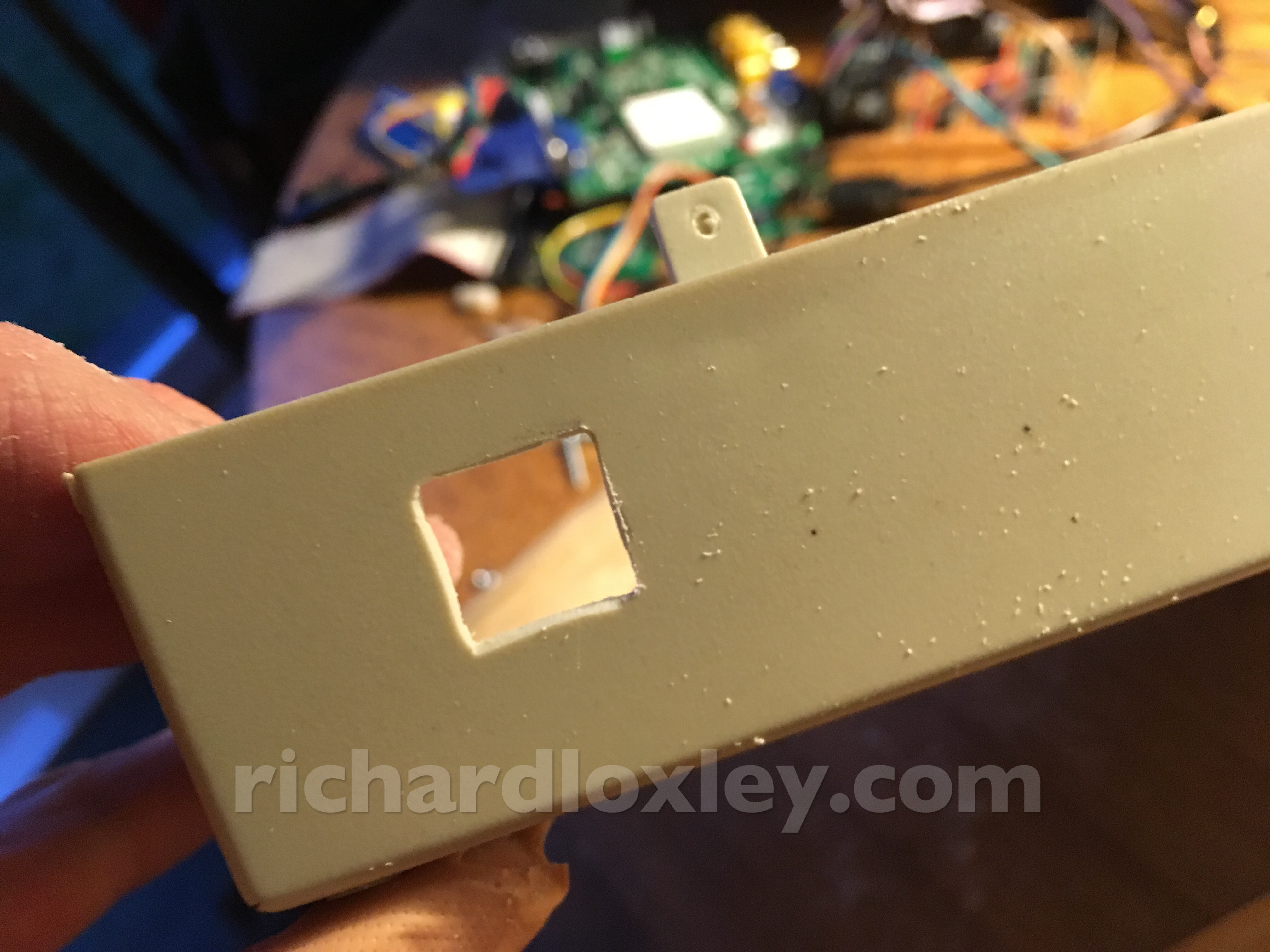
Oops. I did think to myself “I’ve got to be carefully drilling straight towards the USB port on the Arduino with my power drill”.
I went slowly. It didn’t make any difference. Stupid boy. Drilled off 3 legs of the serial chip ![]()
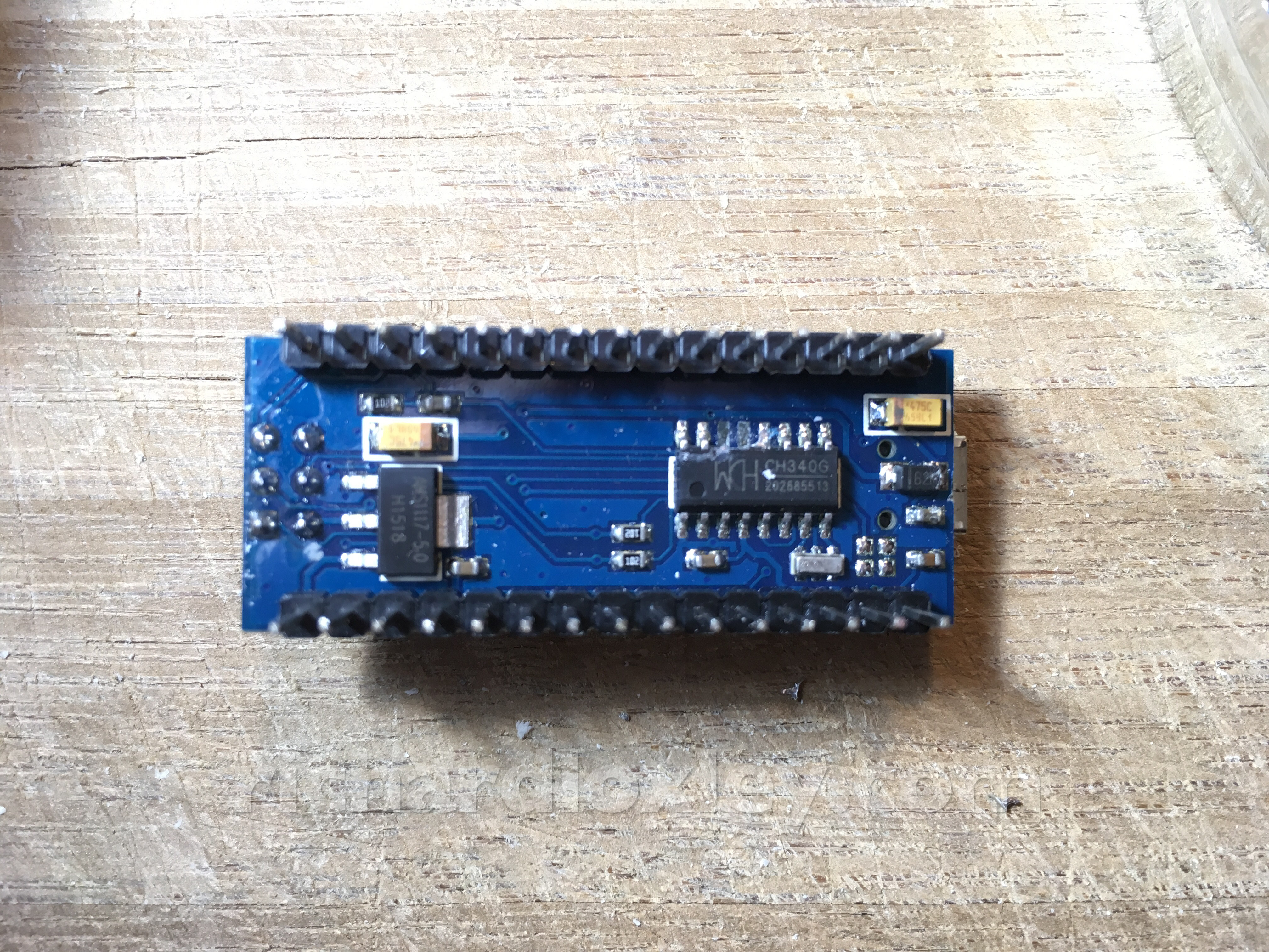
The Arduino still works, but I can’t reprogram it. Oh well. Despite being a fully-fledged computer, it’s one of the cheapest components in there!
I could get another for £3.10, delivered by Monday. I paid an extra 68p to have one with the header pins already soldered on so I can plug it straight in when it arrives. It would have taken me a good half hour to do that myself, so I’m saving myself a job that only pays £1.36/hour ![]()
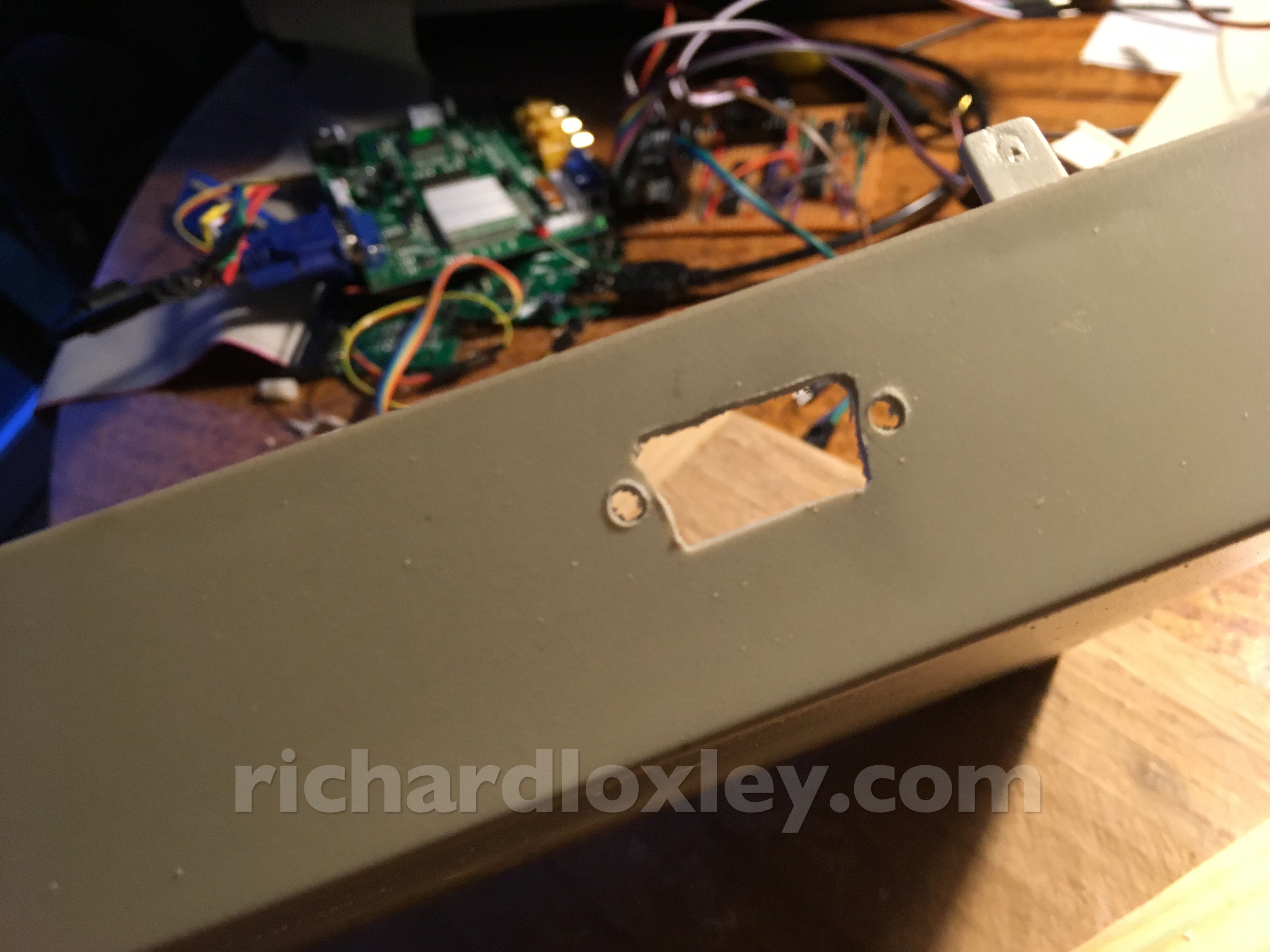
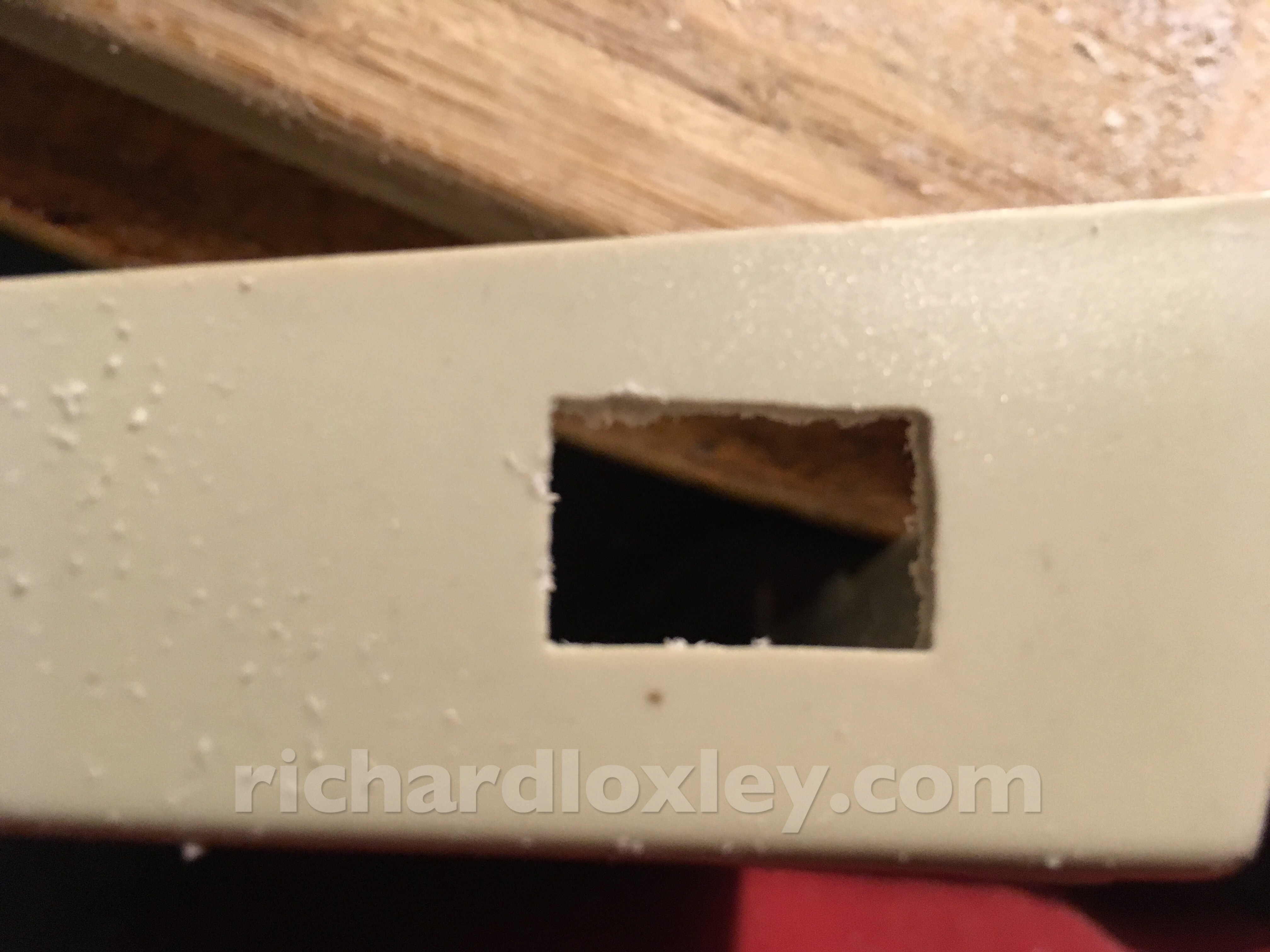
Making a hole for the VGA socket:
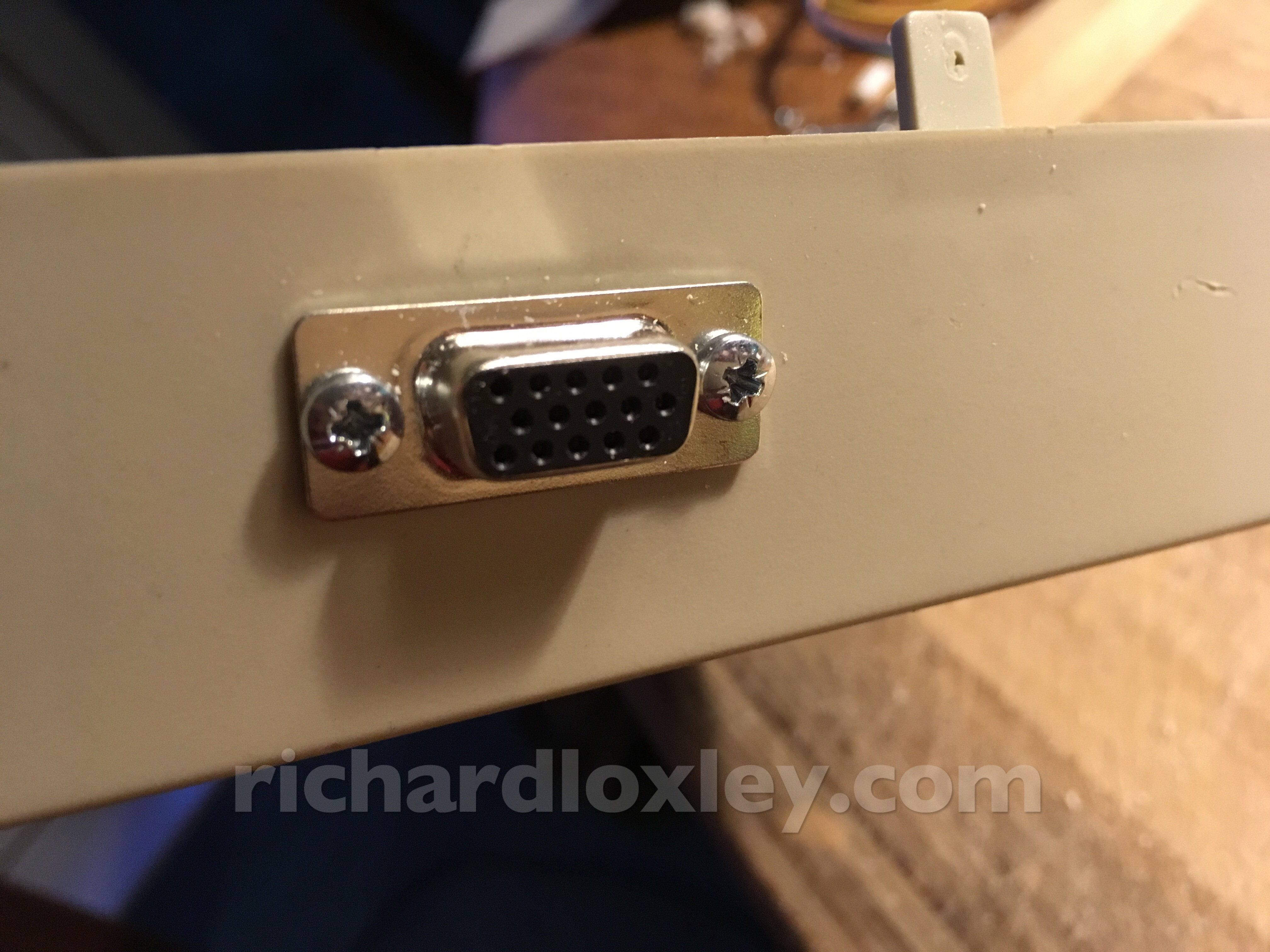
And the VGA socket installed:
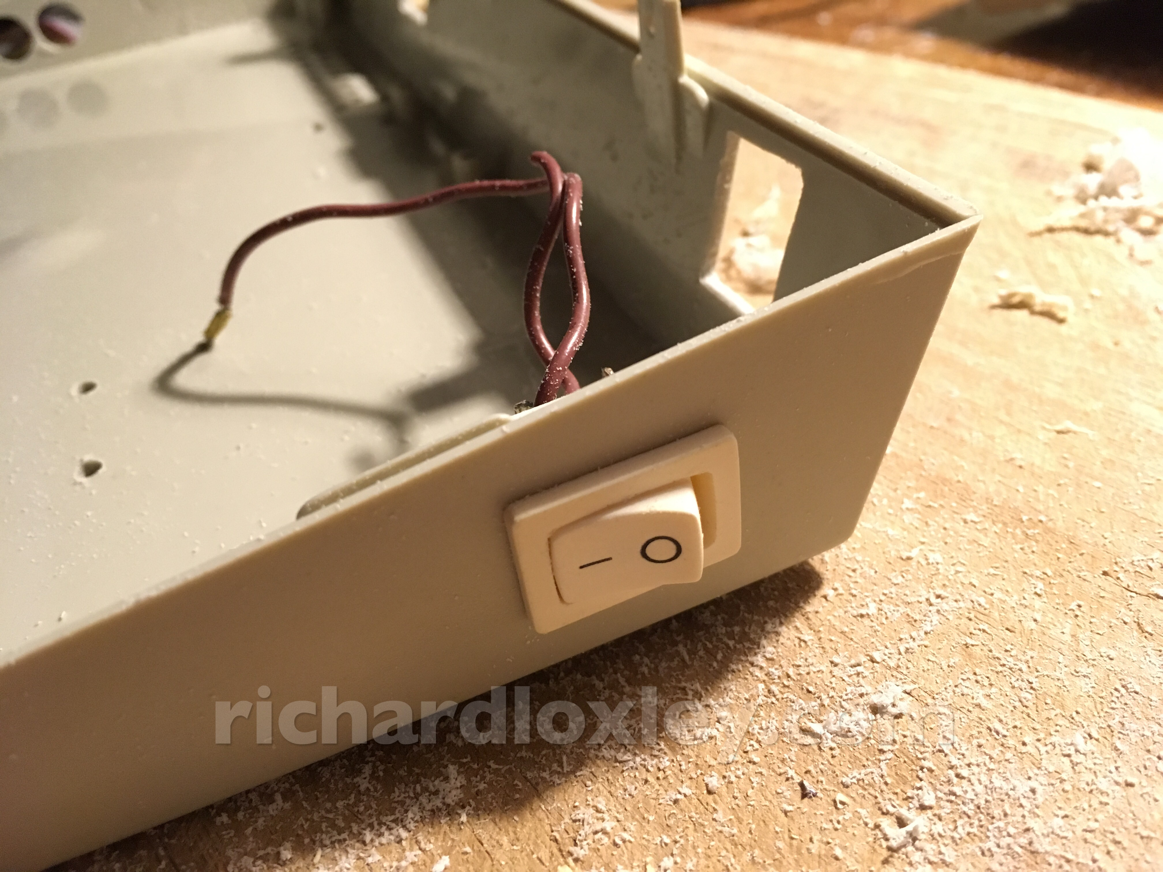
Hole for the power switch:
Power switch installed. This is one I rescued from some obsolete equipment in the past (probably a fluorescent strip light) thinking it might come in useful sometime.
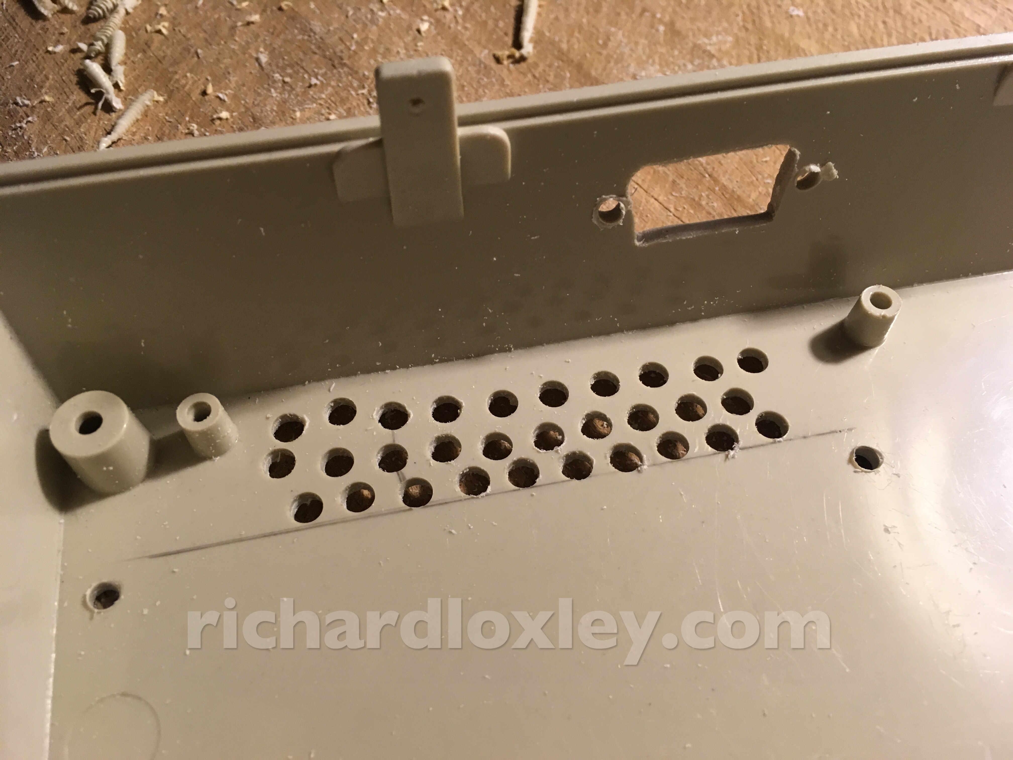
I drilled some ventilation holes in the bottom. The video board has a heat sink that gets very hot, so I want to set up a convection air stream near it.
Since these are hidden on the bottom, I just did them by eye. My eye obviously isn’t very good!
I planned out the ventilation holes on the back to make a neater job.
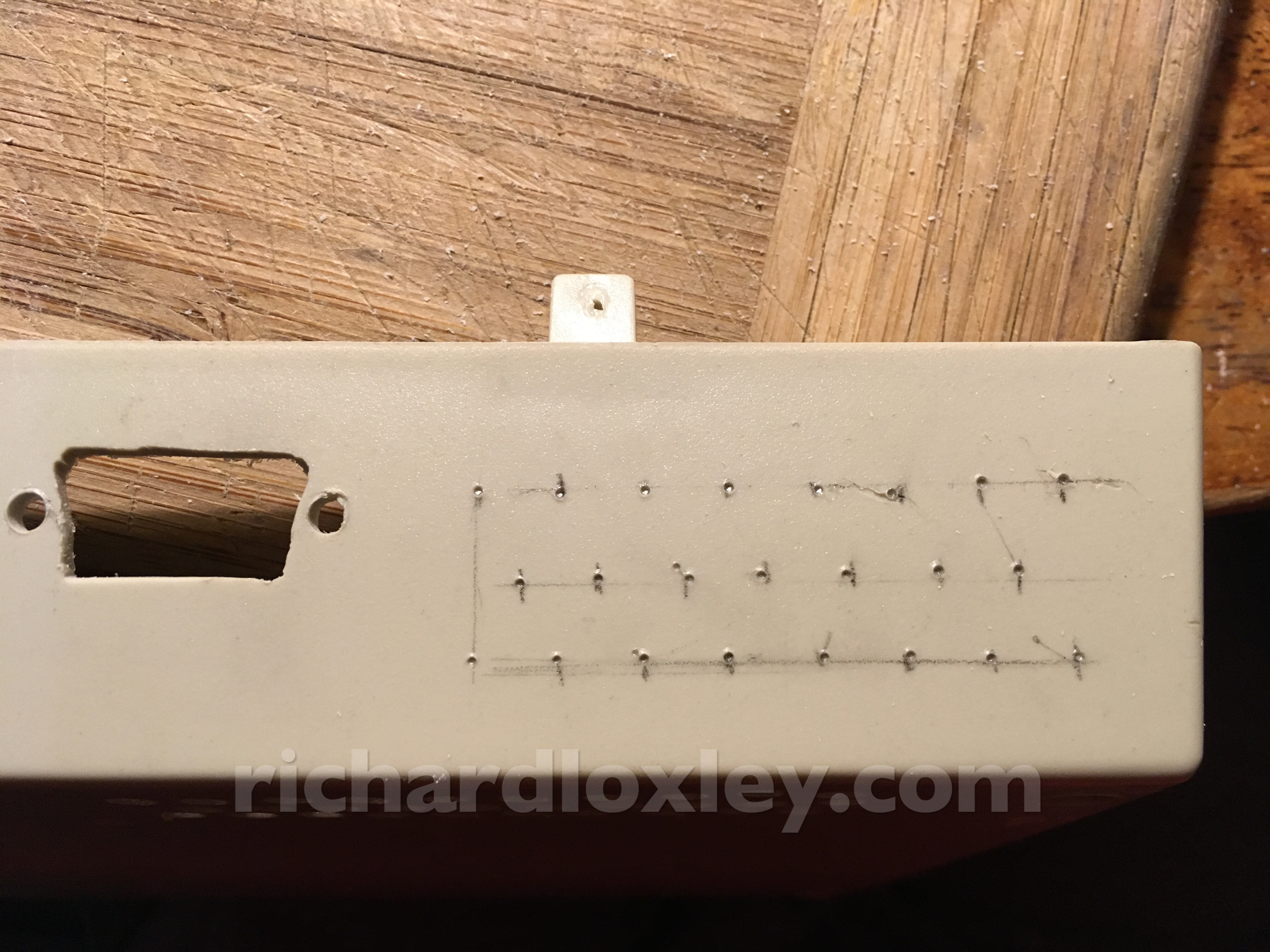
Better than the bottom, but still not that great. Even with a centre punch hole, the plastic is so soft the drill drifts really easily.
Oh for a drill press. Or even better, a CNC machine.
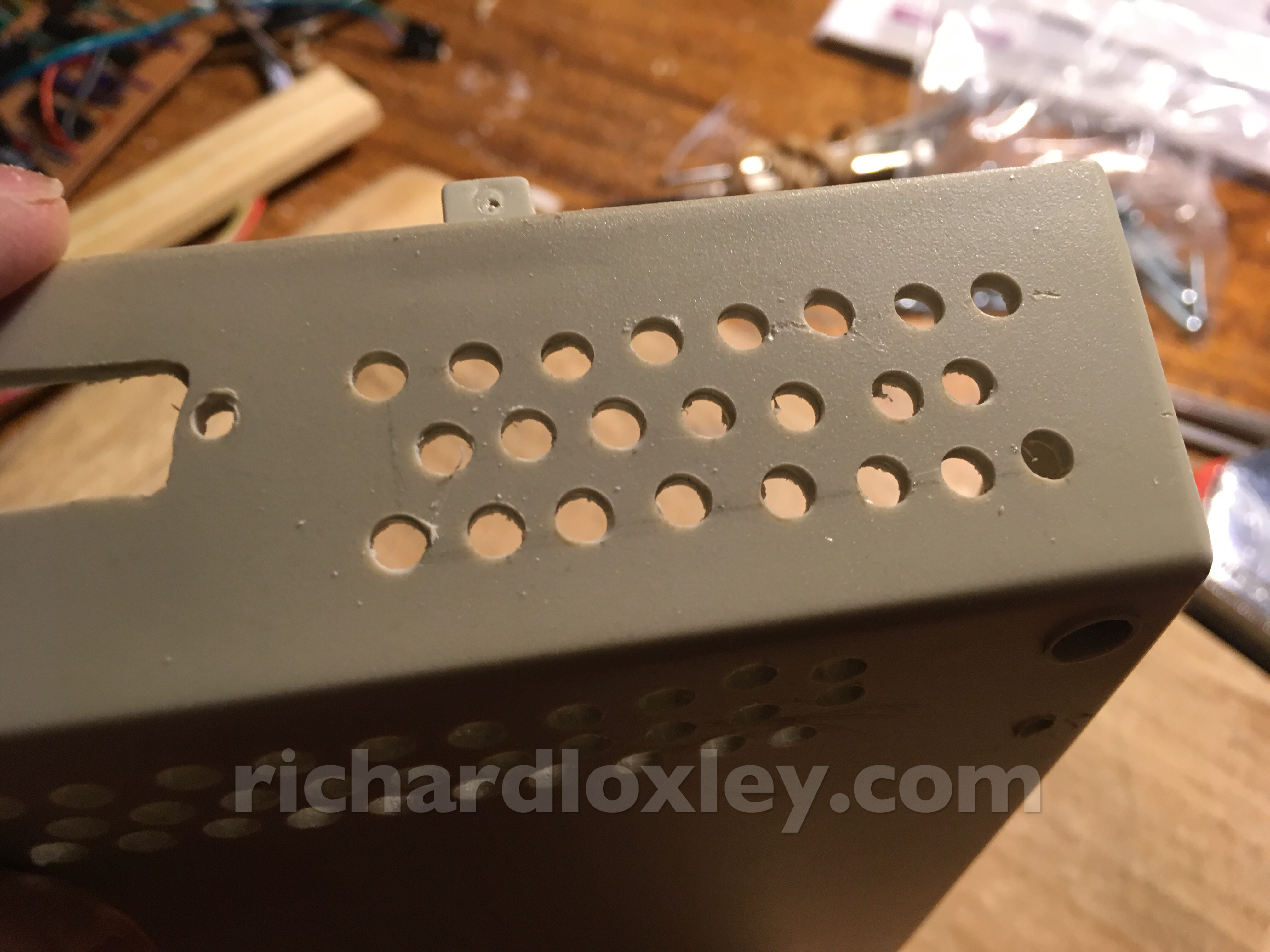
Here are the ventilation holes next to the heat sink. I’ll also add some higher up at the back.
All the electronics installed. Still to do on the lower half: the power socket. But that’s still in the post ![]()
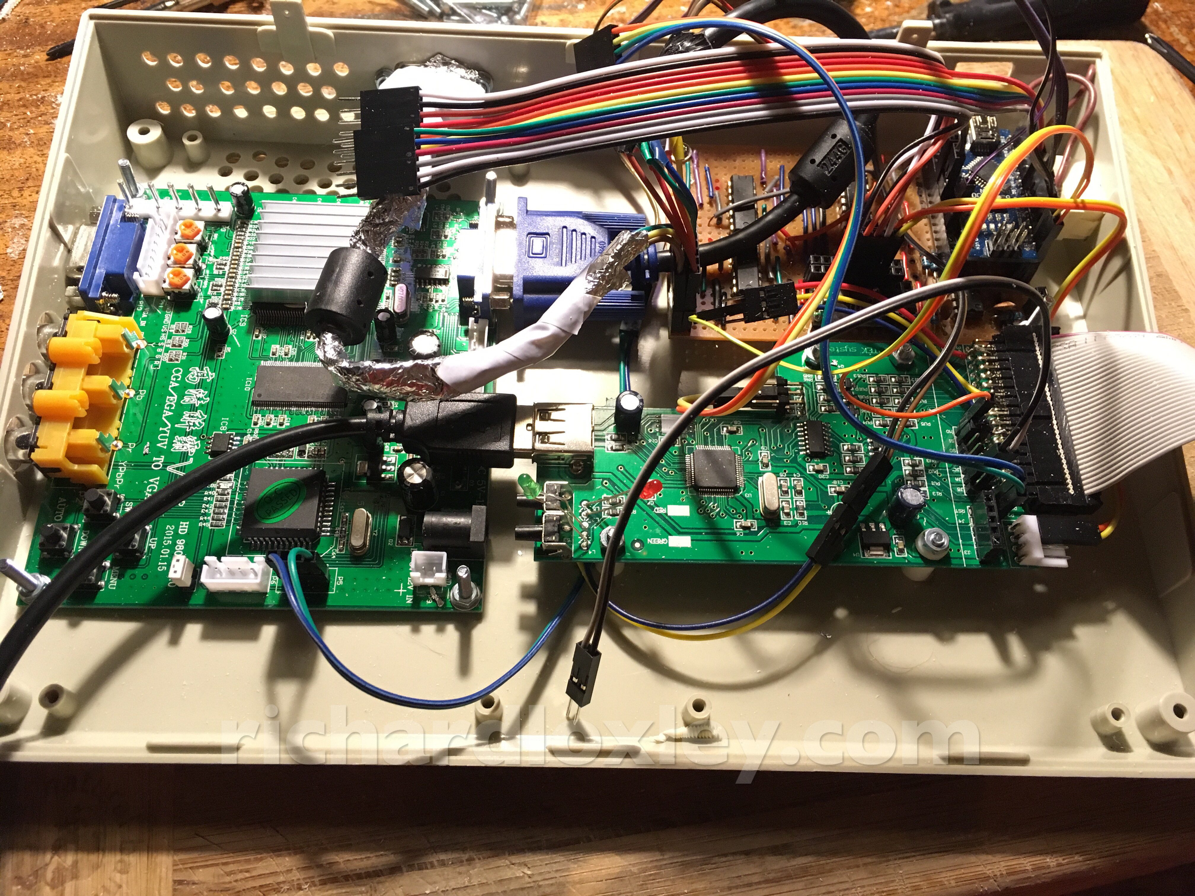
Reconnecting all the cables and testing: everything still works ![]()
The next job is to mount all the remaining ports in the top half of the case. That’s the USB socket for the memory stick, two floppy drive ports, and the SCART socket.
That’s for another day.