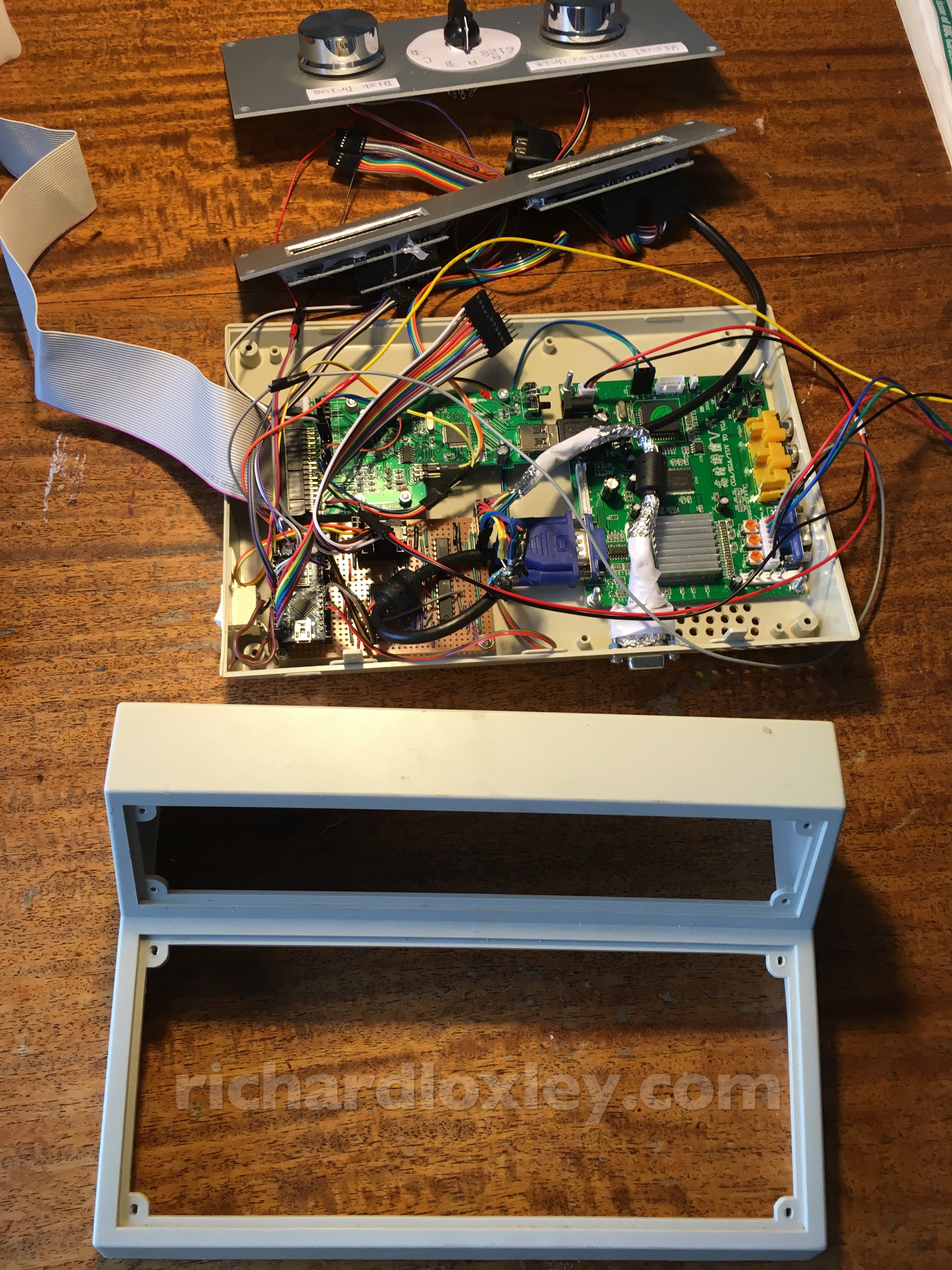
Yesterday I mounted all the components in the lower half of the case.
Today’s job is to do the top half :-)
(TL;DR: This post is pretty much just a photo journal. If you just want to see the end result, scroll to the bottom!)
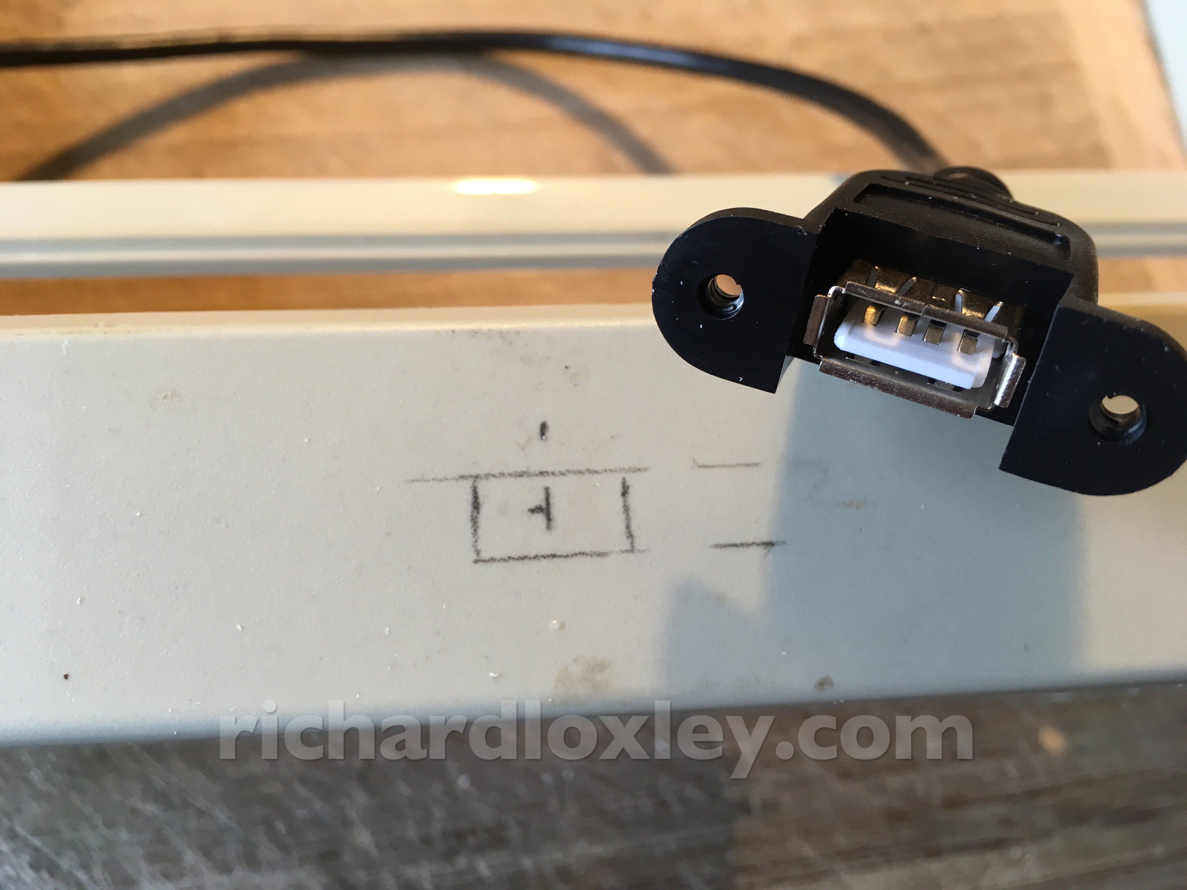
Control panels removed so I can start cutting holes in the top of the plastic case:
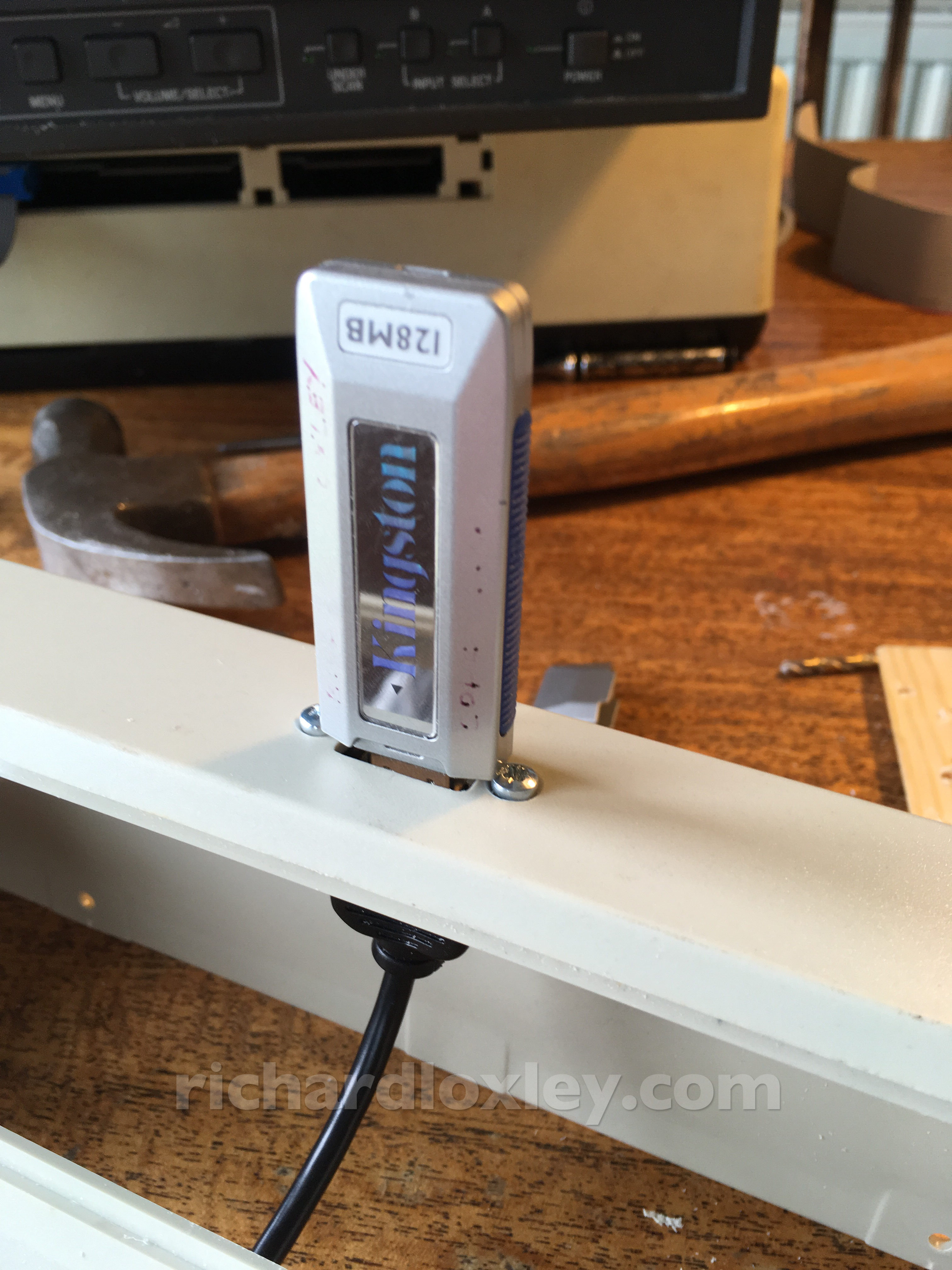
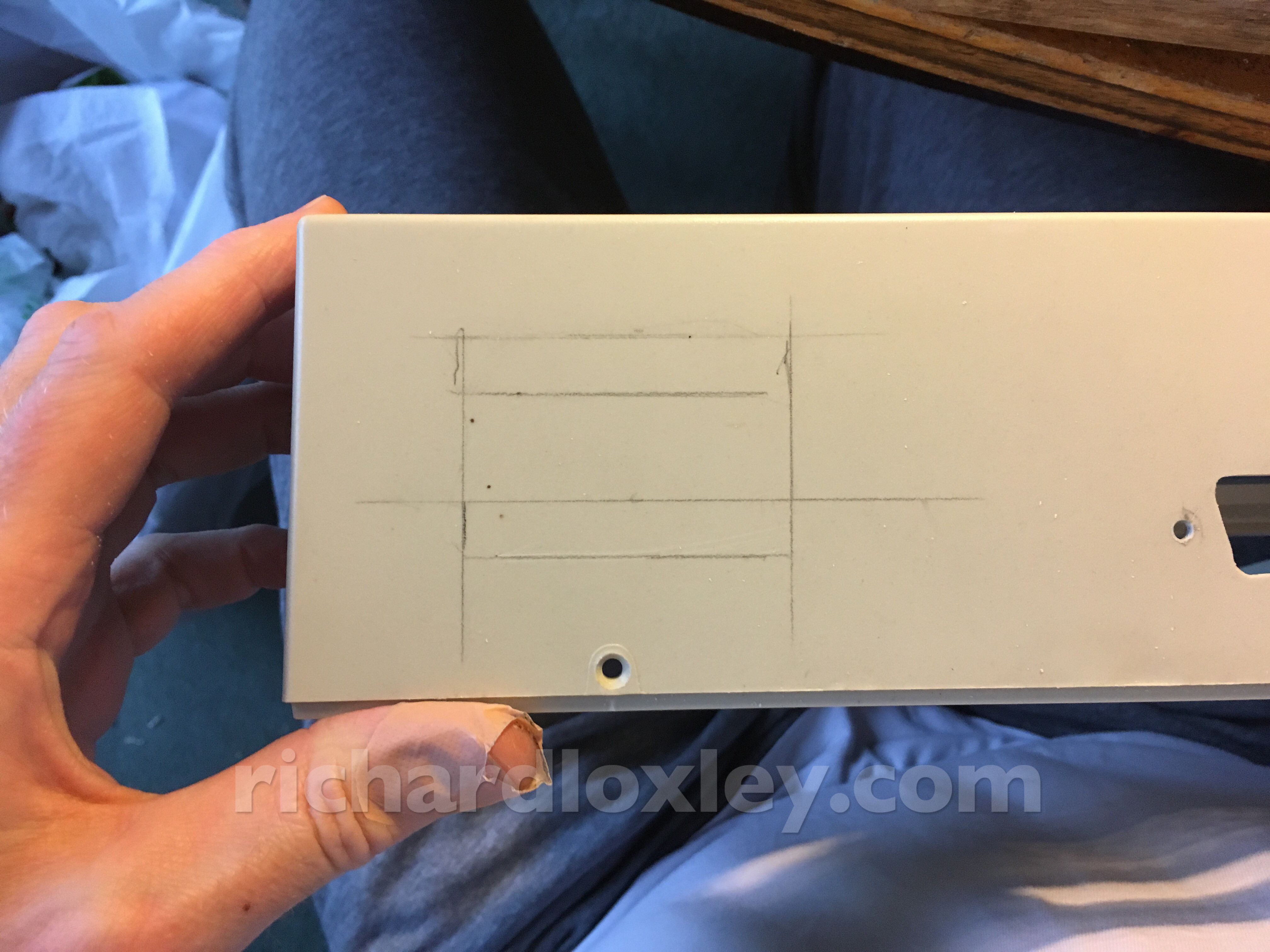
Marking out the USB socket. This will be the most visible hole on the case, and the socket has no bezel to cover imperfections, so I need to do a good job!
It took a lot of very gentle filing, but I’m happy with that ![]()
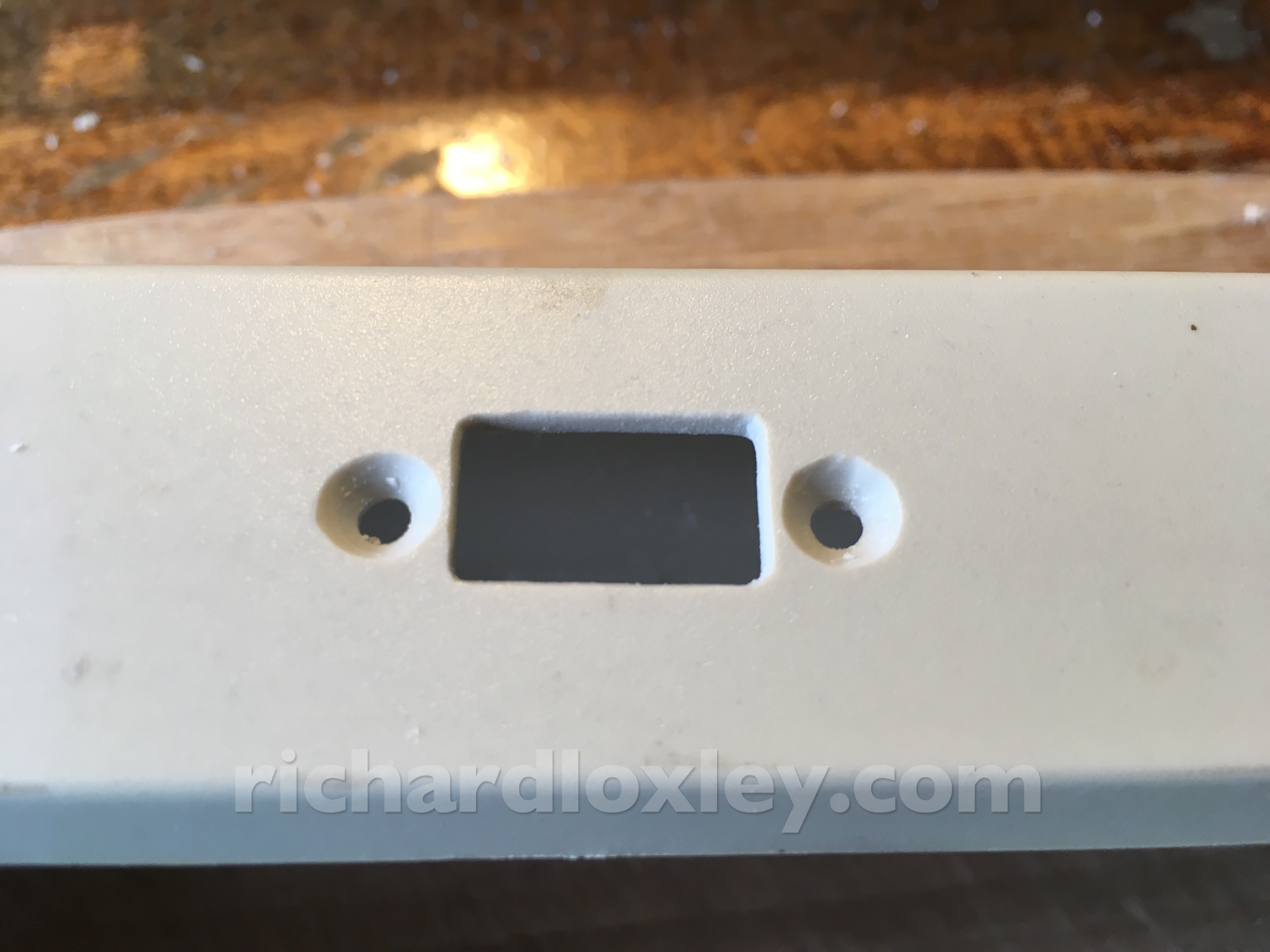
The socket mounted. It’s not 100% central as the screw holes are very slightly off (bloody drill drifting on the soft plastic). But it will do.
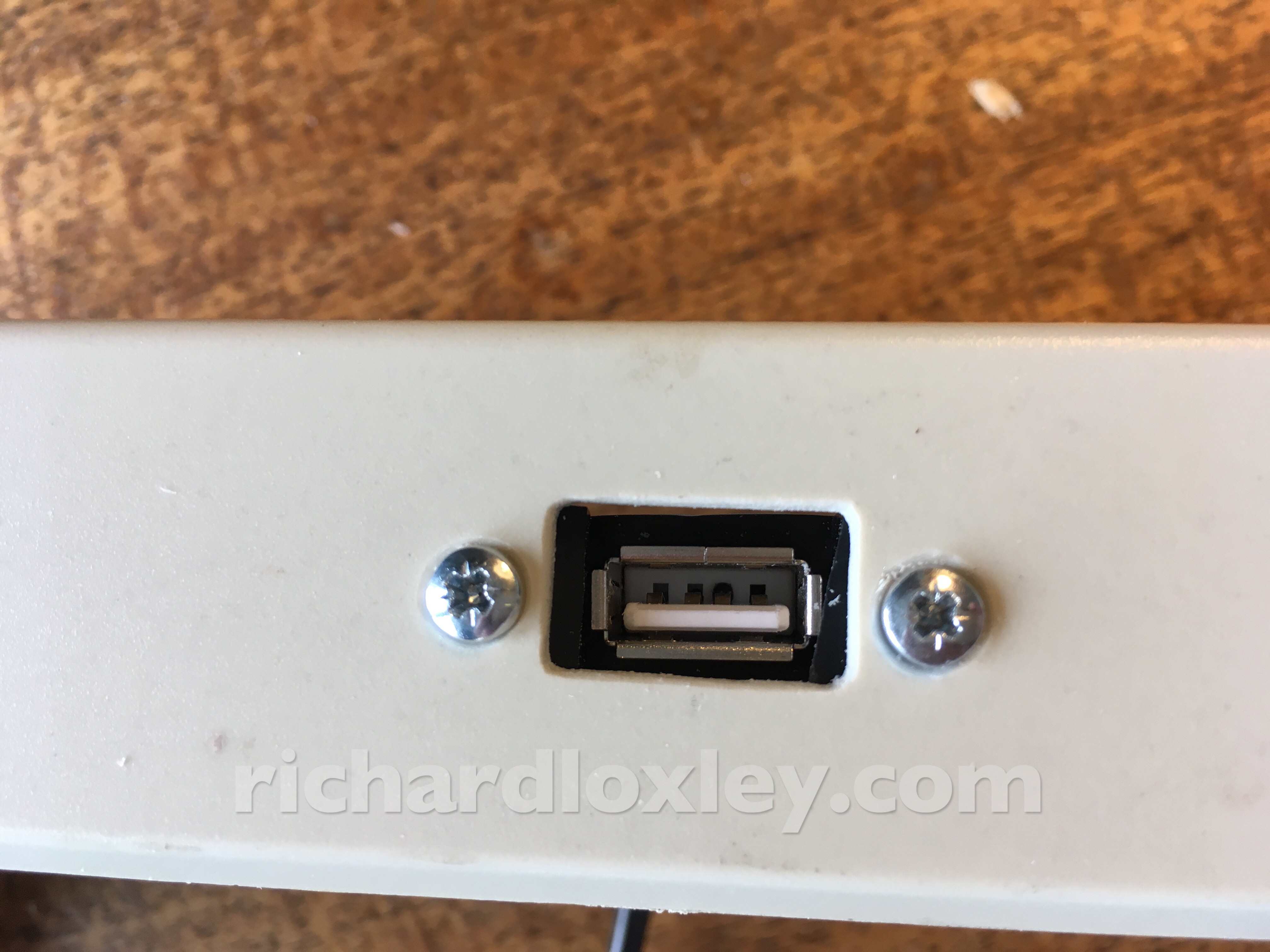
(Edit: once I added nuts to the end of the bolts and tightened it up, I managed to get it central, which was nice.)
Testing the fit:
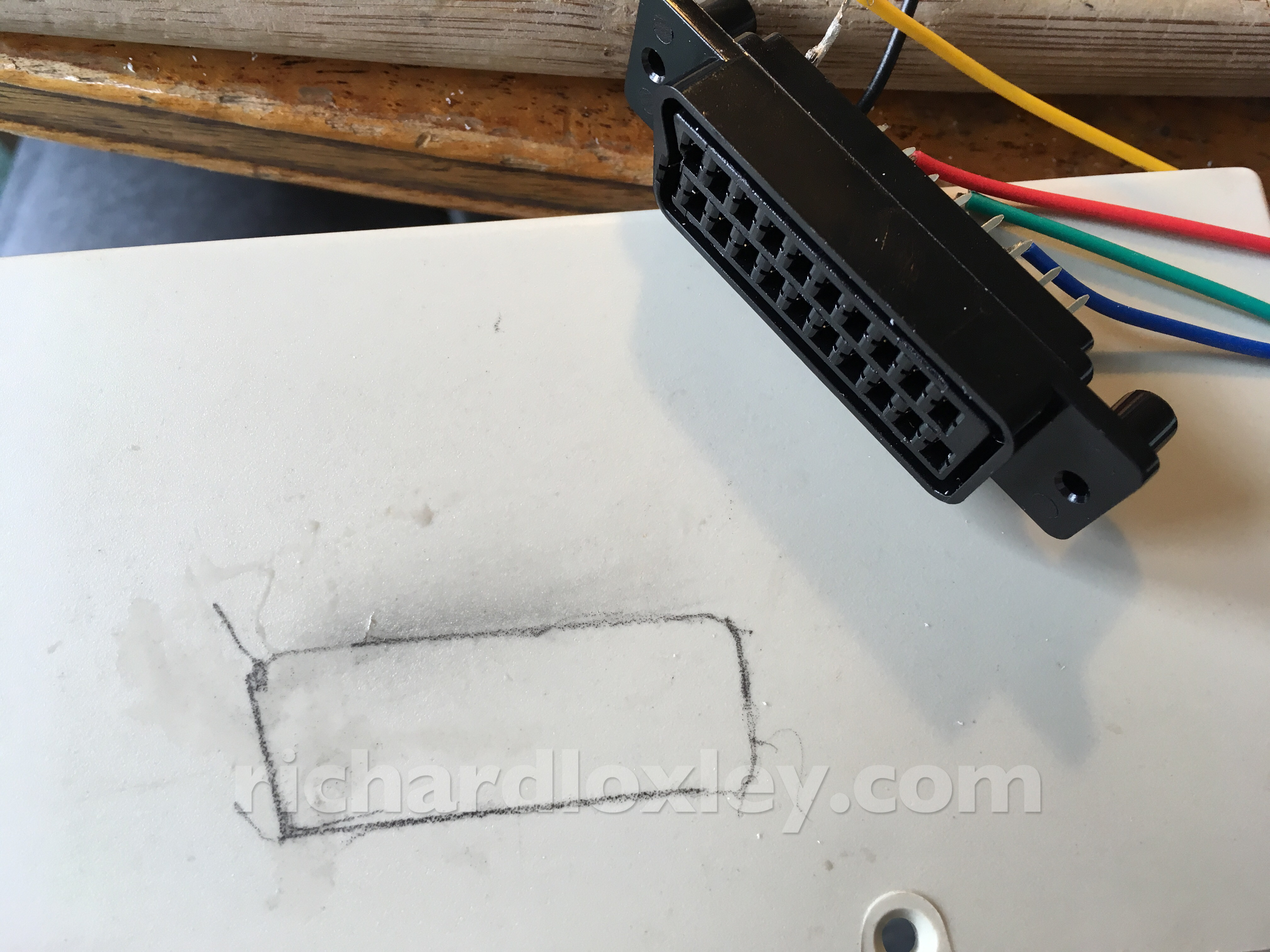
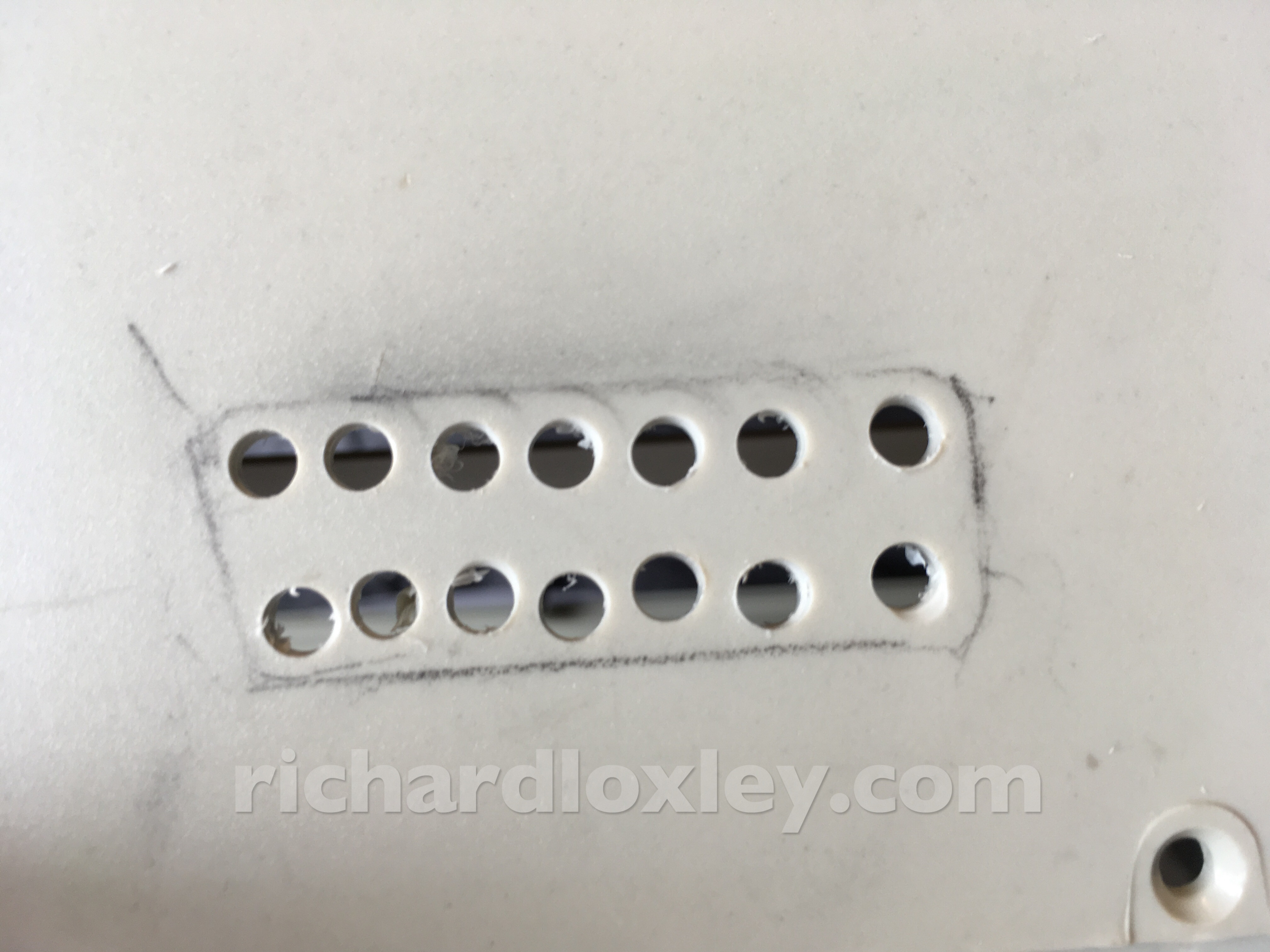
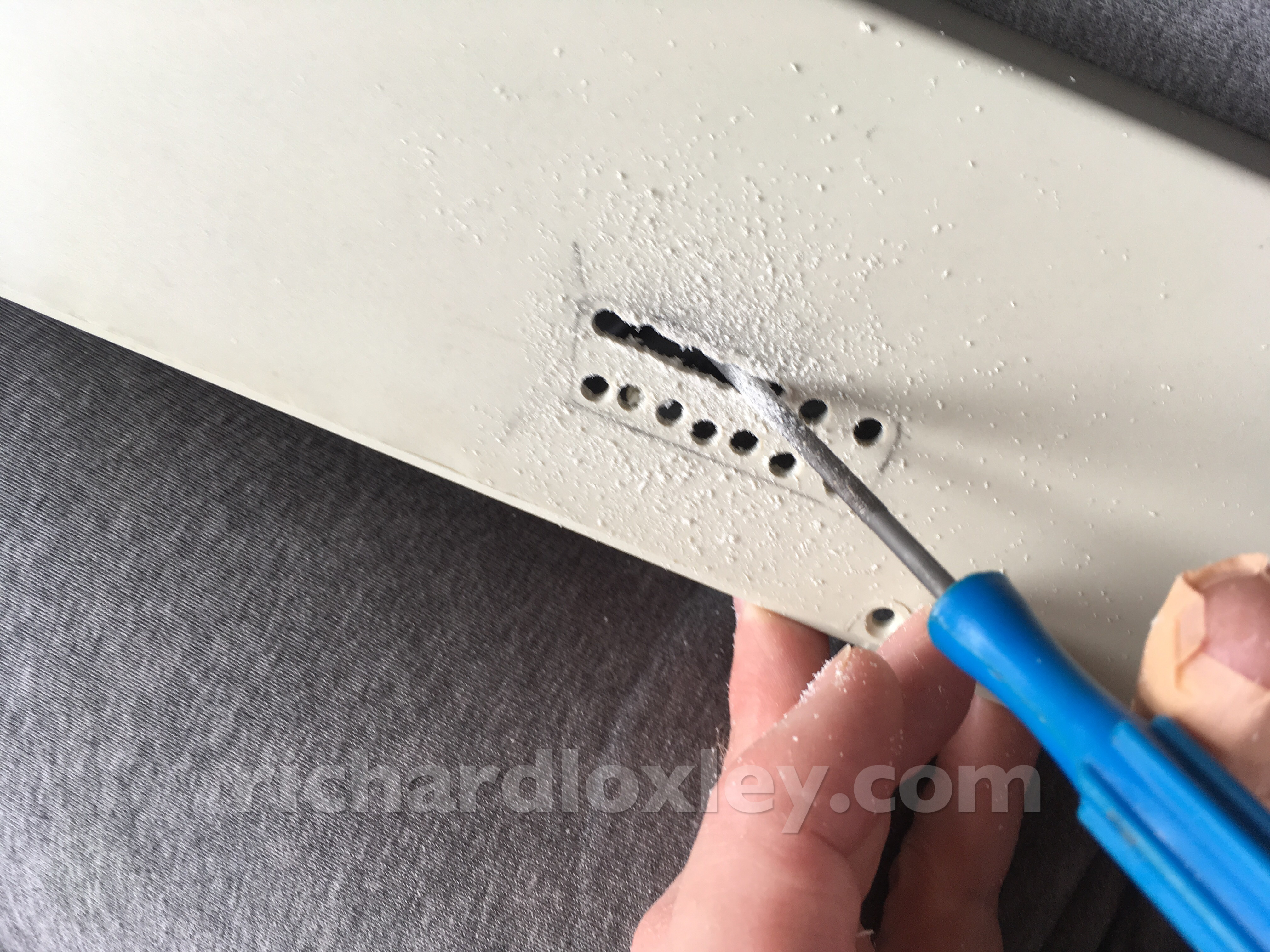
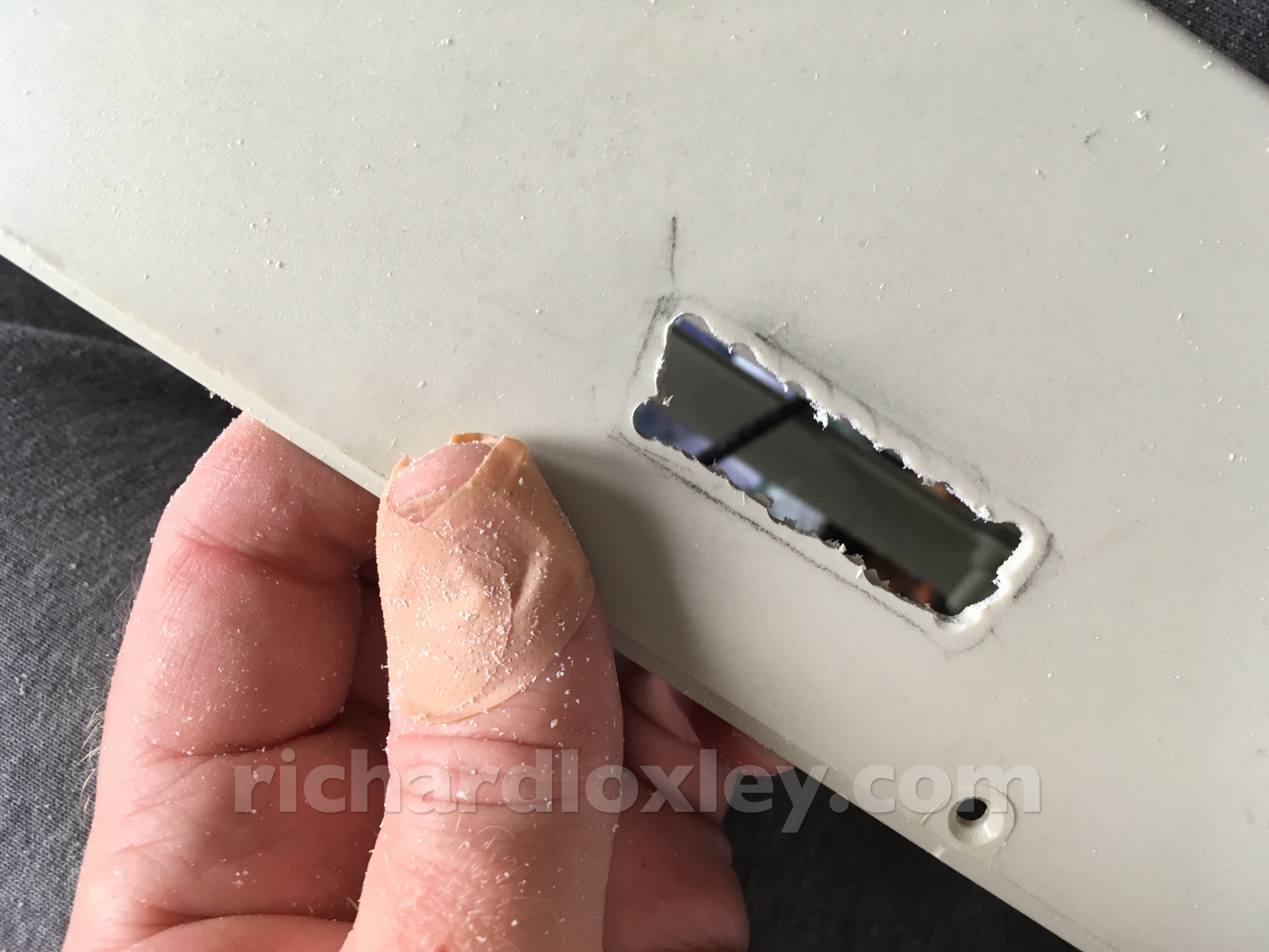
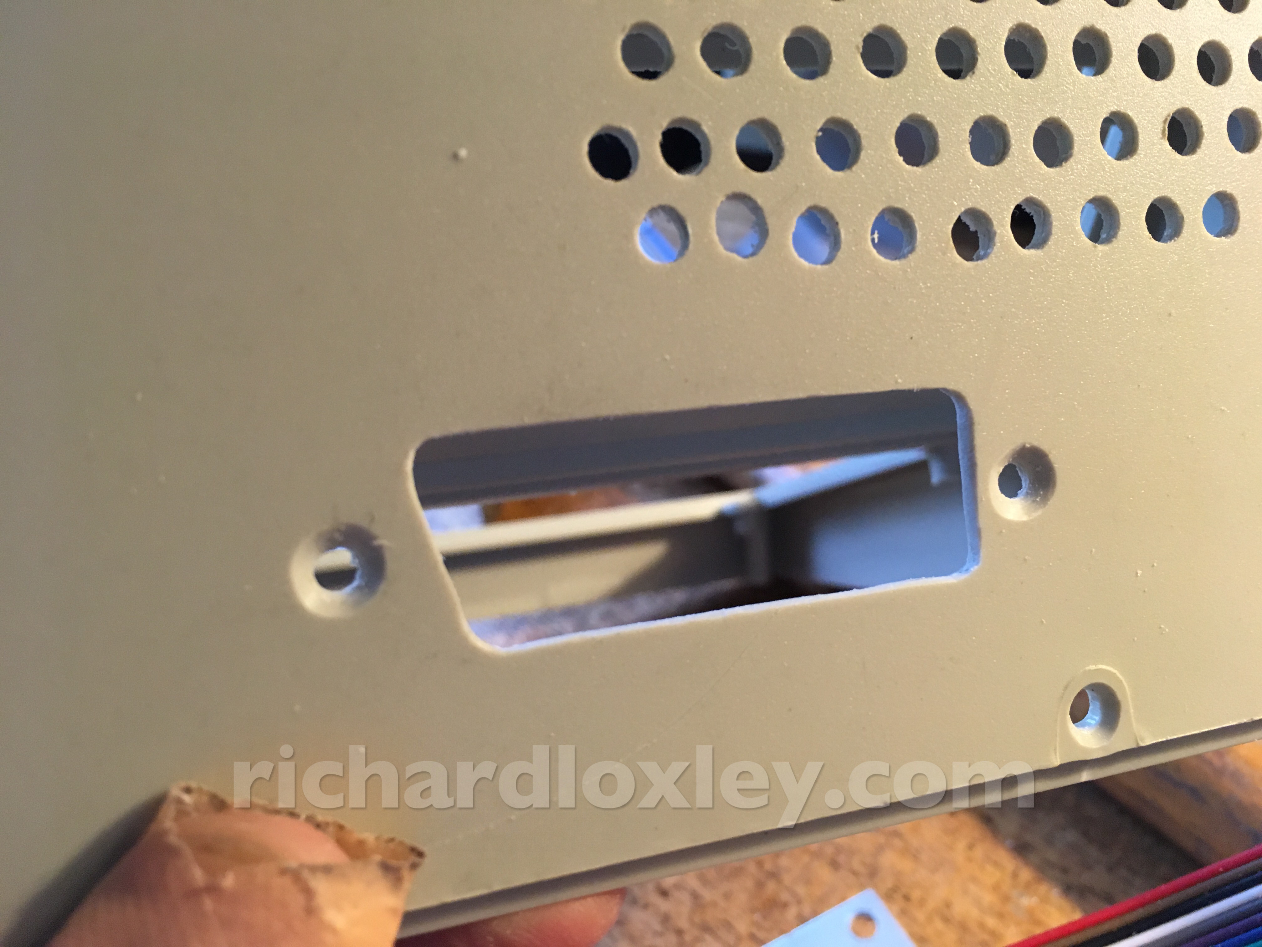
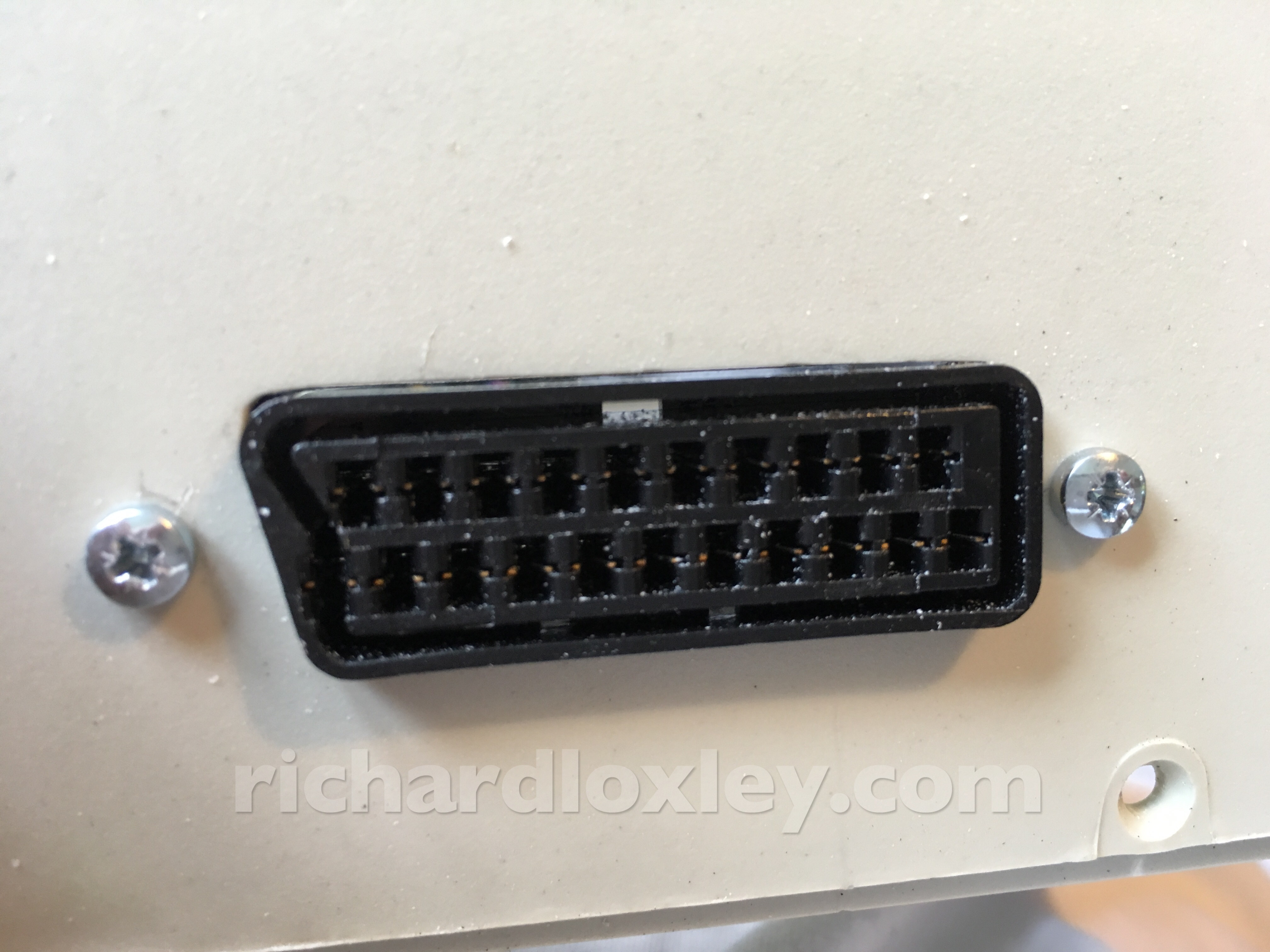
SCART socket:
Upper ventilation holes:
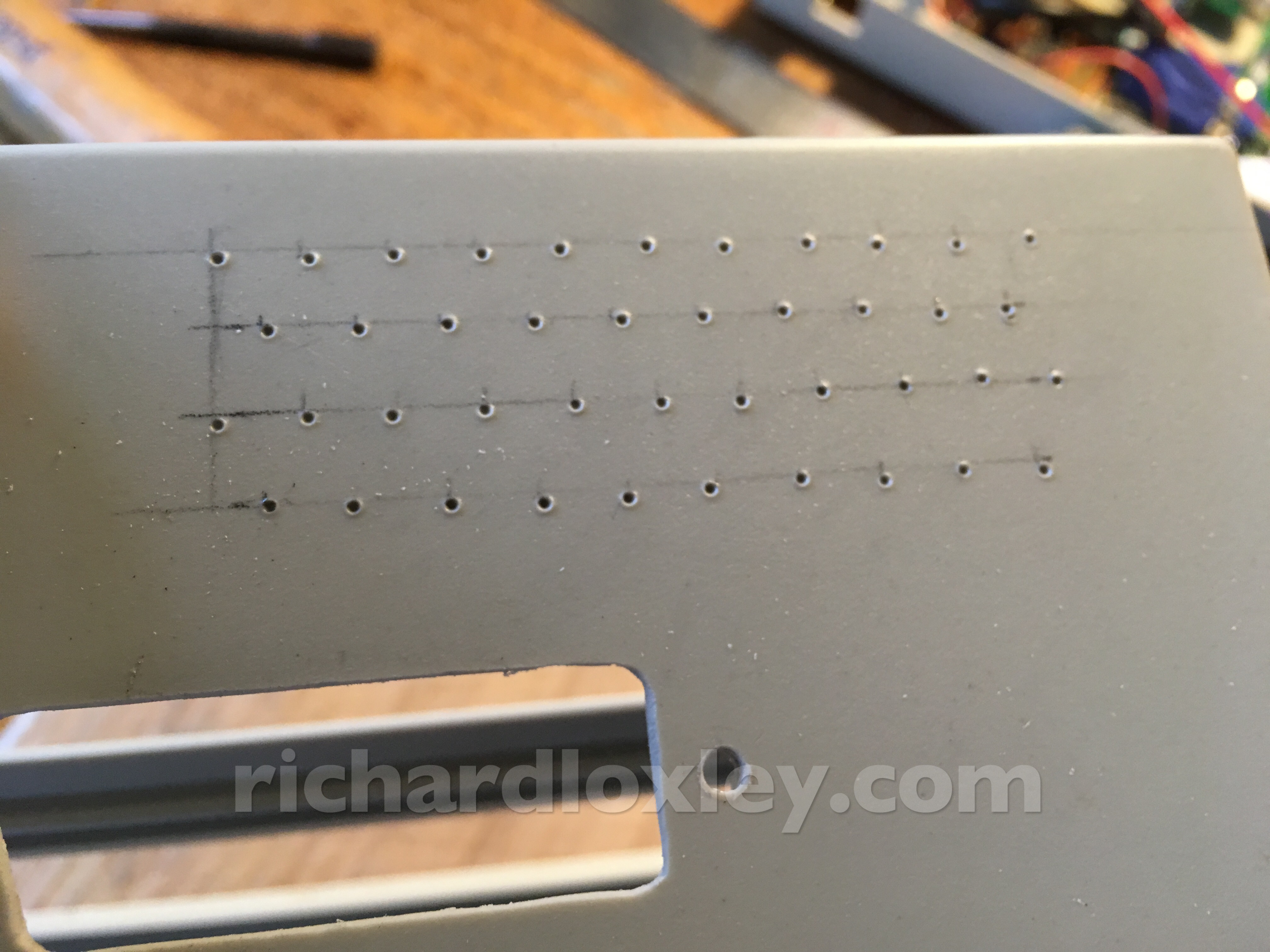
The drill is still slipping, but I found that knocking the drill down to its lowest speed and going at a walking pace helped:
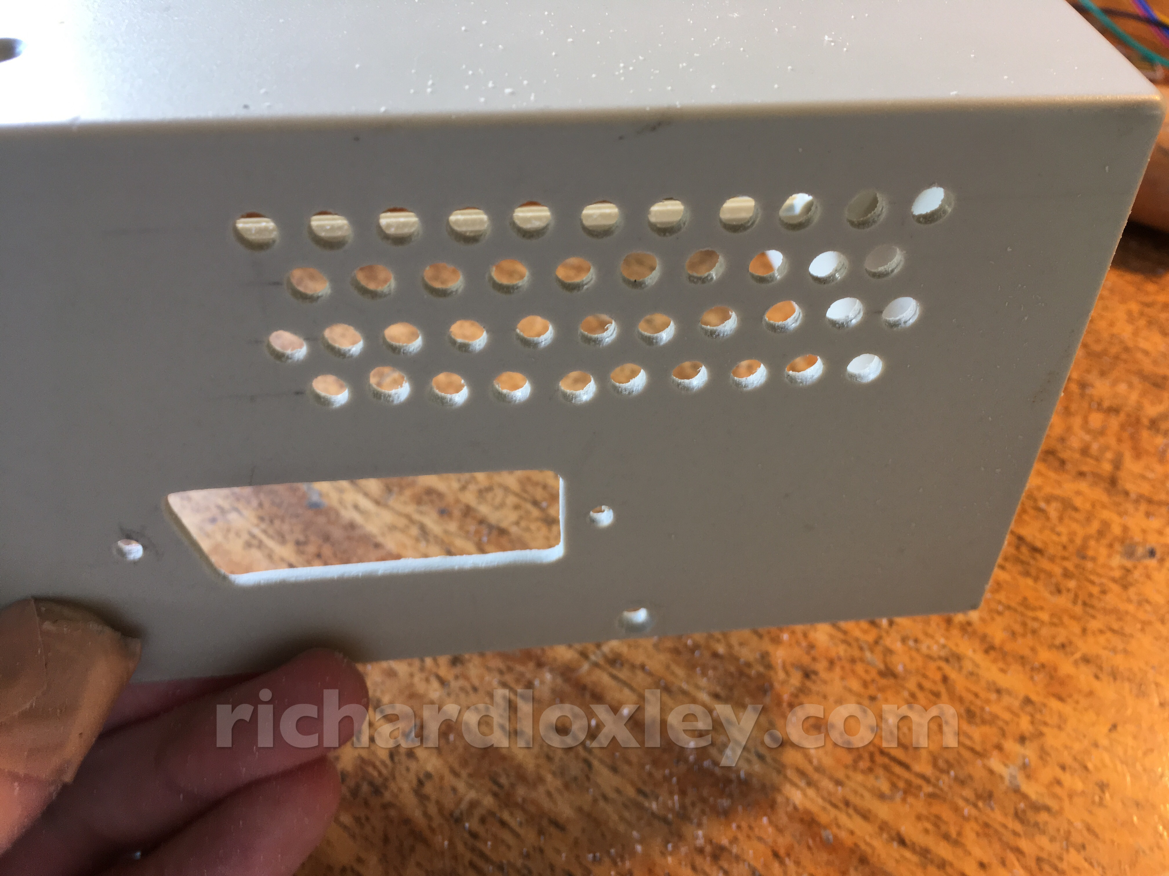
I only discovered this after the first few holes (bottom left) so I elongated them with a round file to disguise how out of line they were ![]()
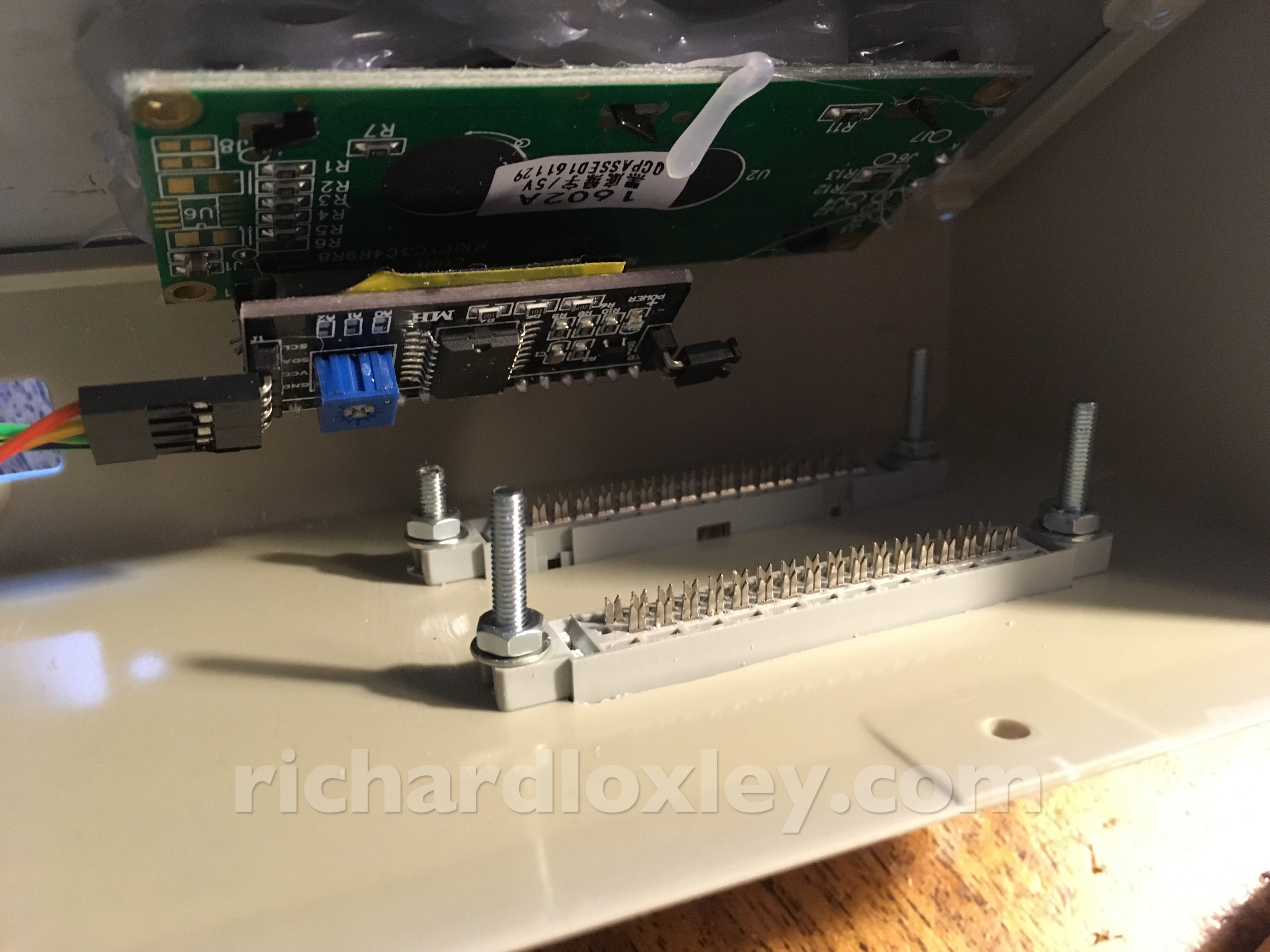
Fitting the floppy ports:
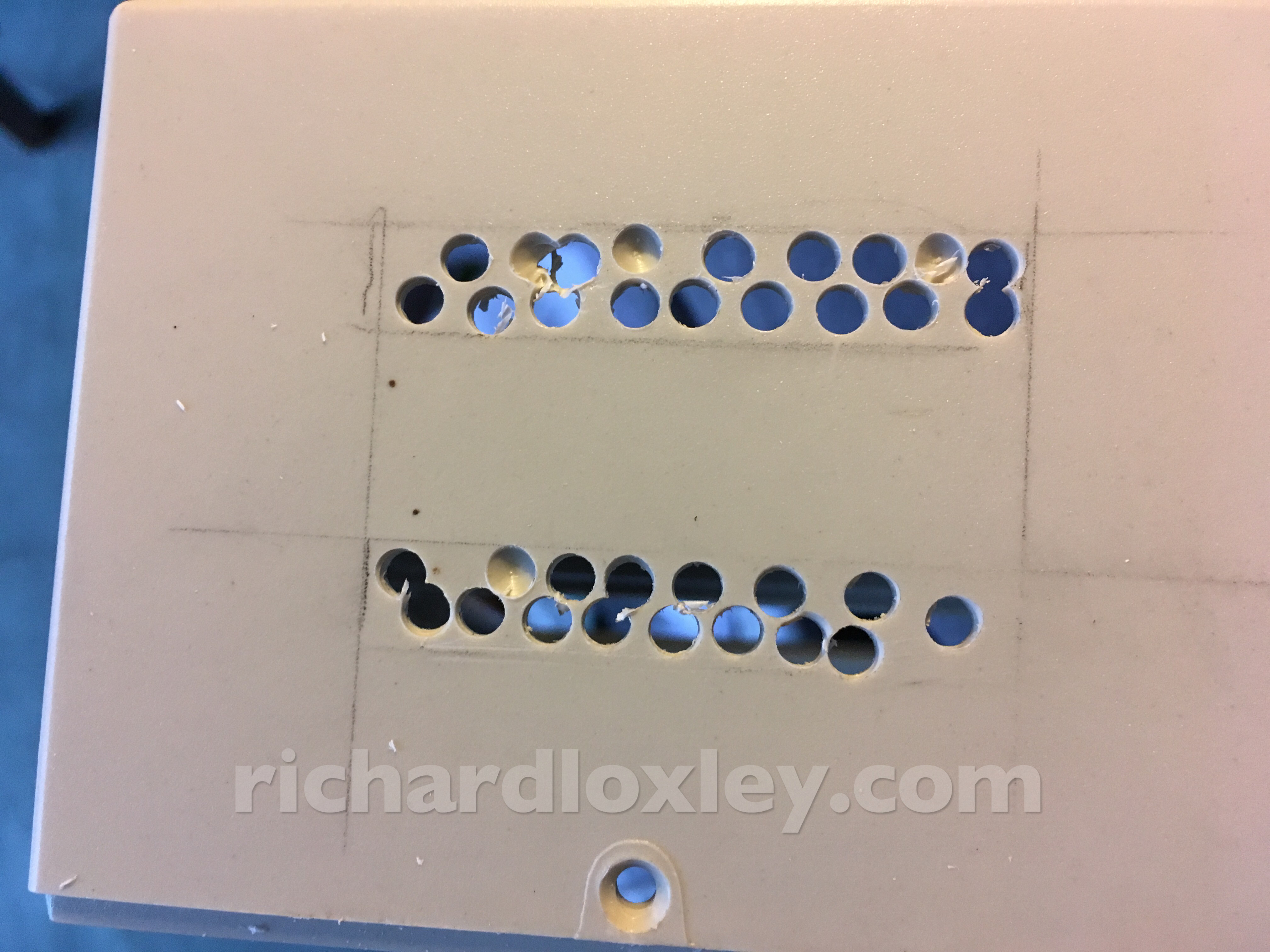
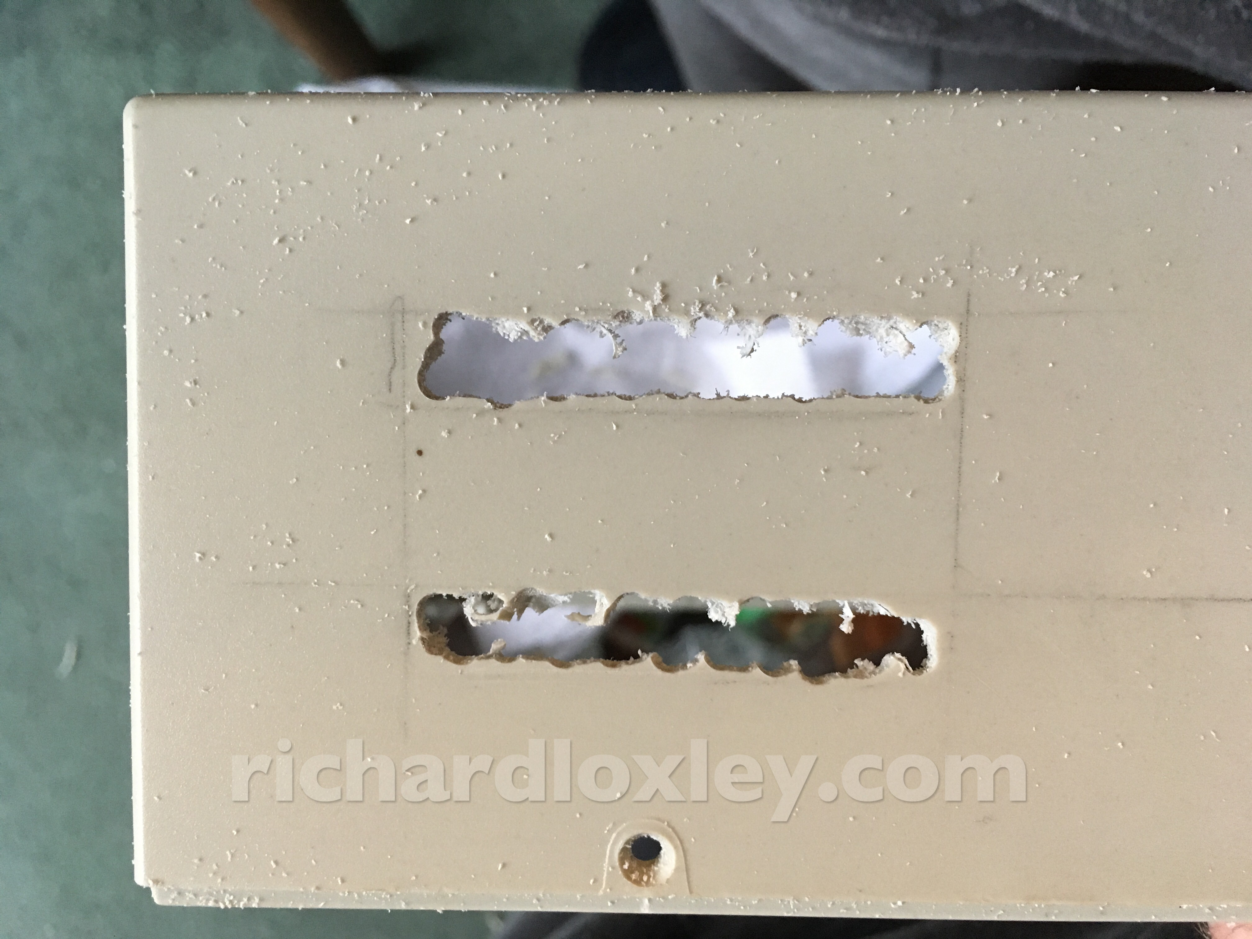
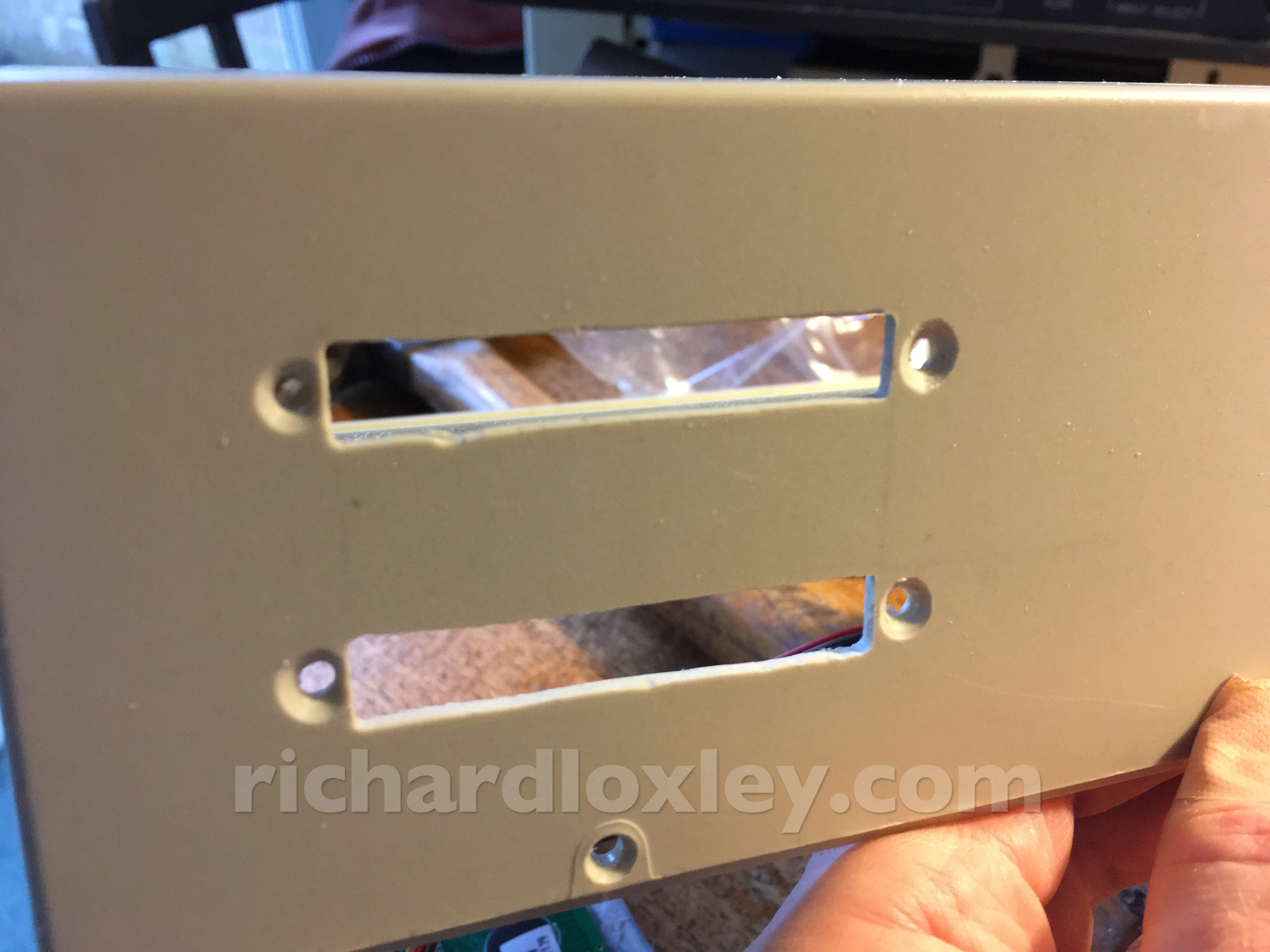
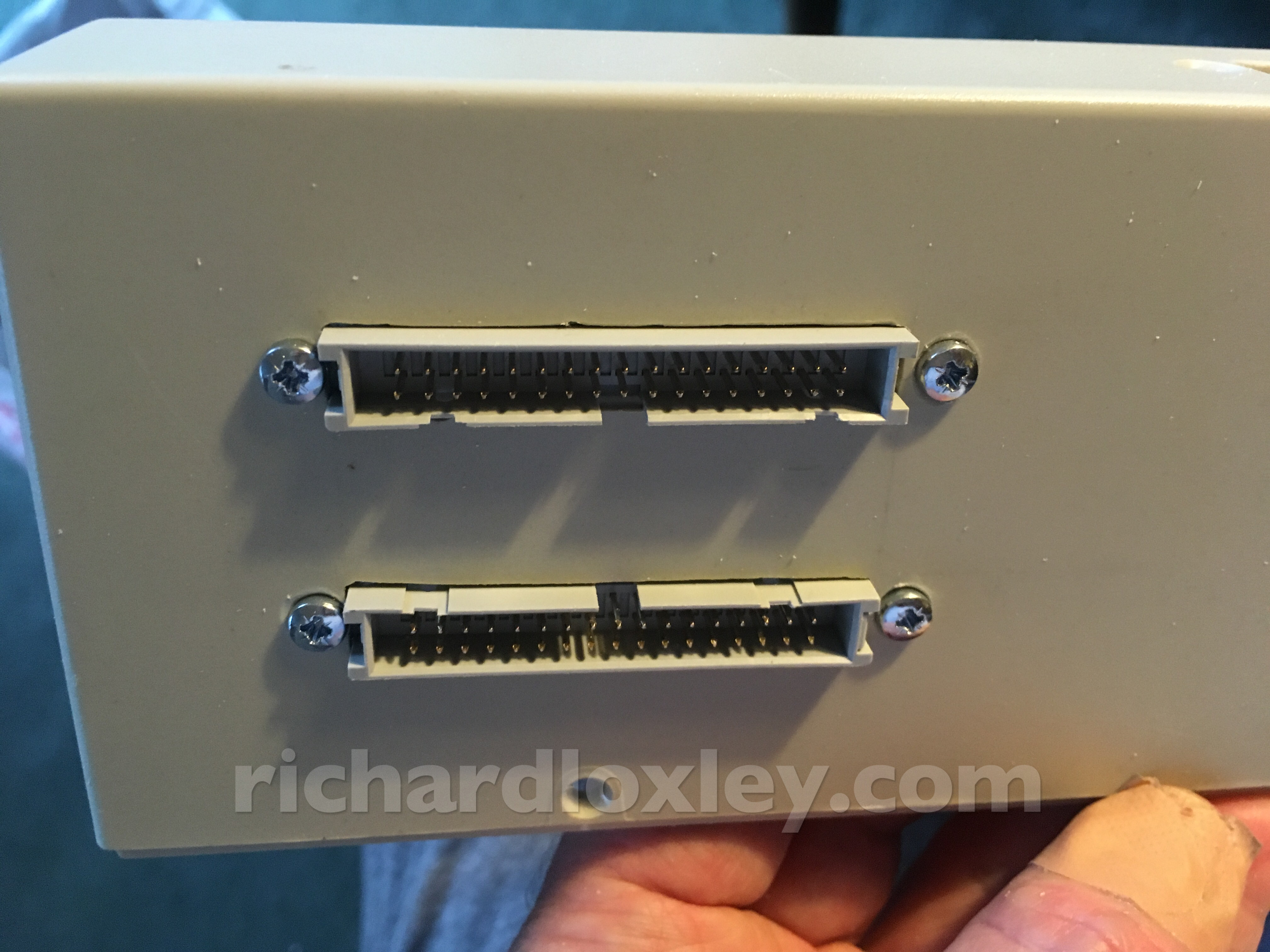
Yes, one is upside down – deliberately. The Amstrad uses a floppy port that is 180° rotated to the standard! Also the 464 needs 5v power on some pins, so I’m having a dedicated port for Amstrads, and another for everything else. Only one can be used at a time.
I haven’t yet wired up the floppy ports as crimping the cable is something new to me, plus I have to wire the Amstrad port to include power, which will be tricky. So that task will wait for another day.
I had to saw off one bolt at the back as it was in danger of shorting out one of the LCD displays!
Then reinstall everything for the finished look…
Left side
Three phono sockets for YUV video. Y is used for monochrome composite, e.g. Video Genie). YUV could be used for ZX Spectrum with a bit of work.
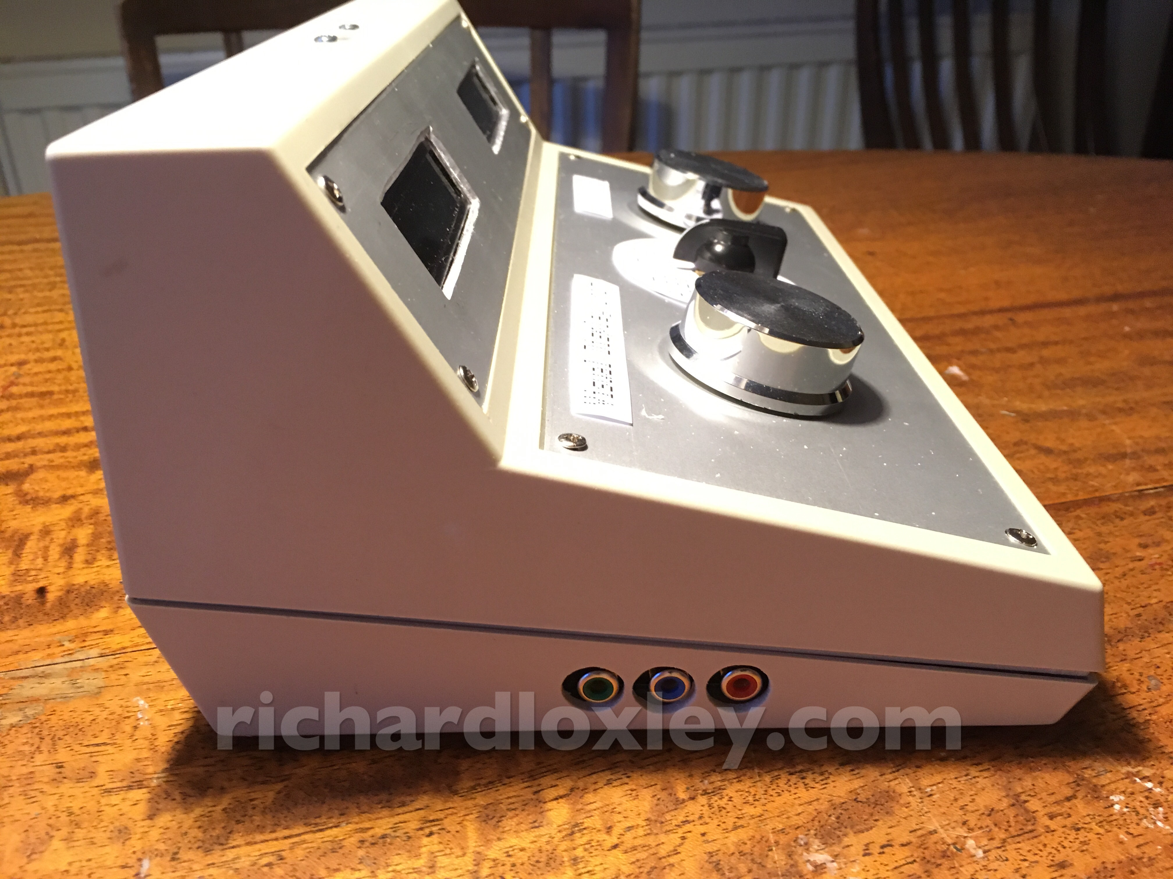
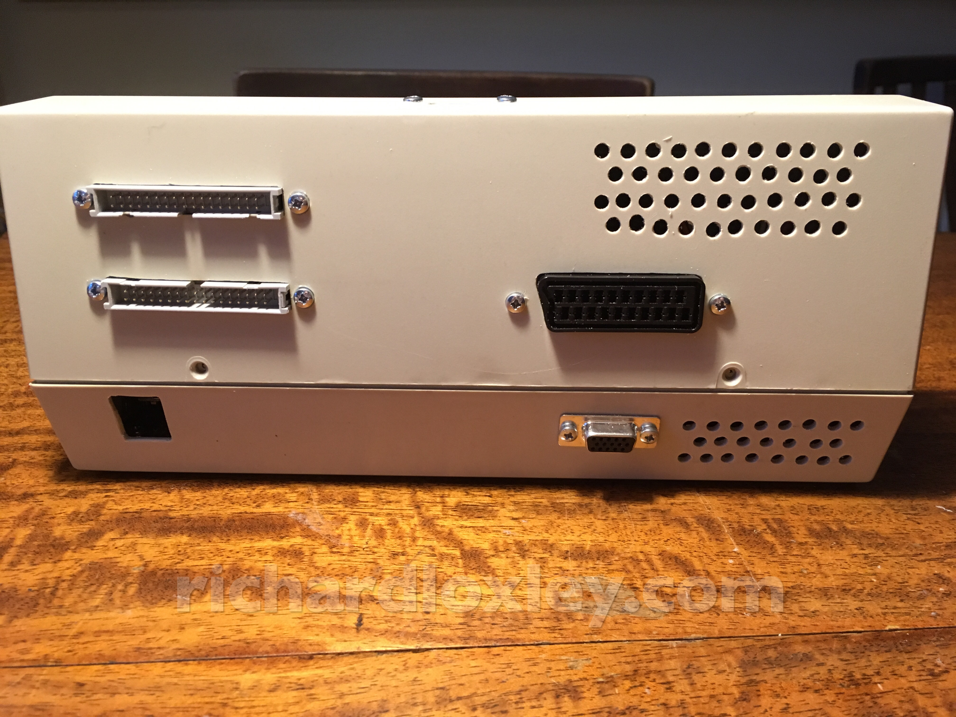
Back
On the left: 2 floppy ports (one for weird Amstrad standard, one for everything else); hole for access to Arduino for reprogramming.
On the right: various ventilation holes to cool the video board; SCART input for RGB/S or RGB/composite (auto selected using the sync splitter circuit); VGA output.
Eventually there will be a power socket in the middle at the bottom.
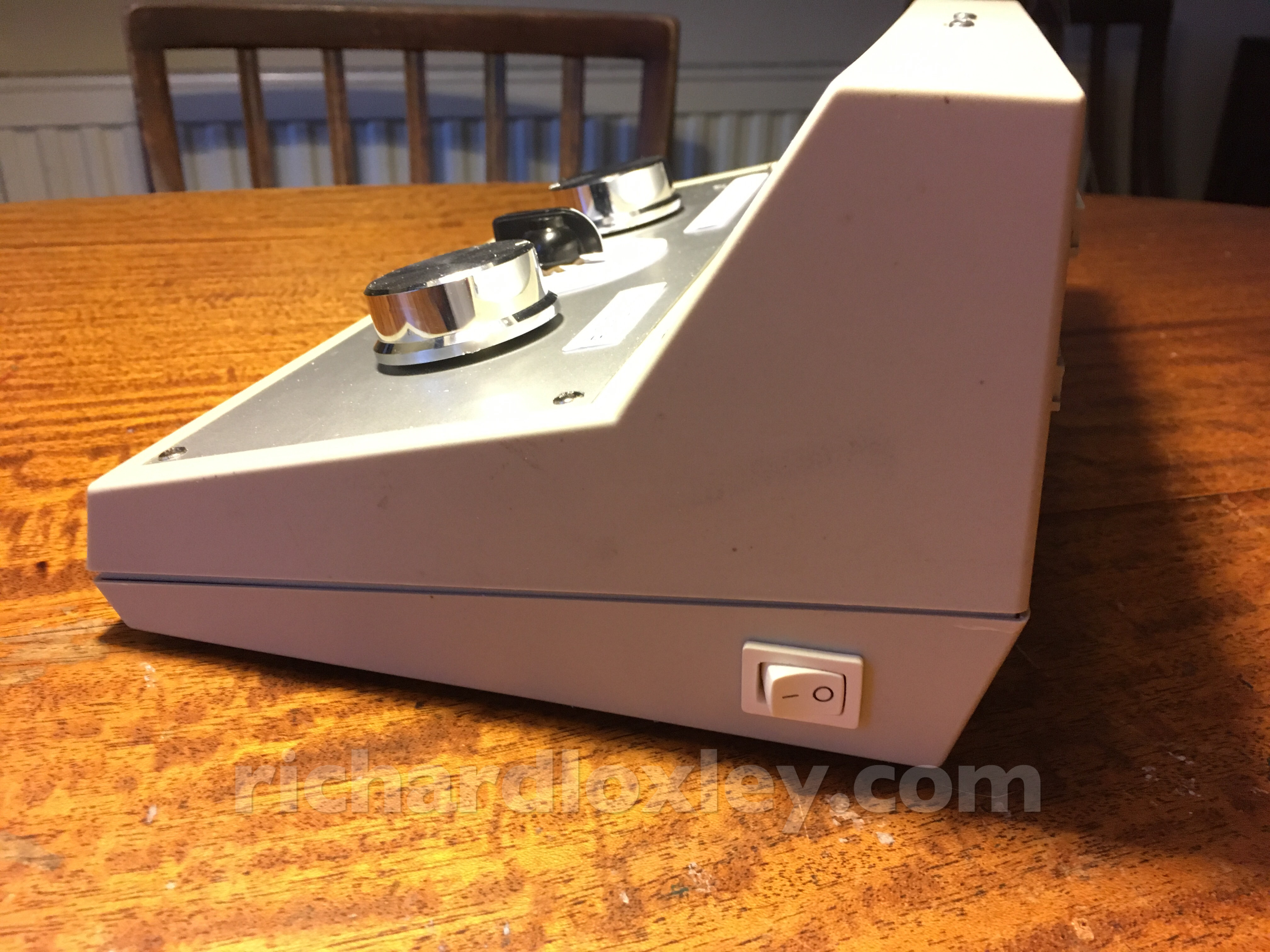
Right side
On this side just the power switch.
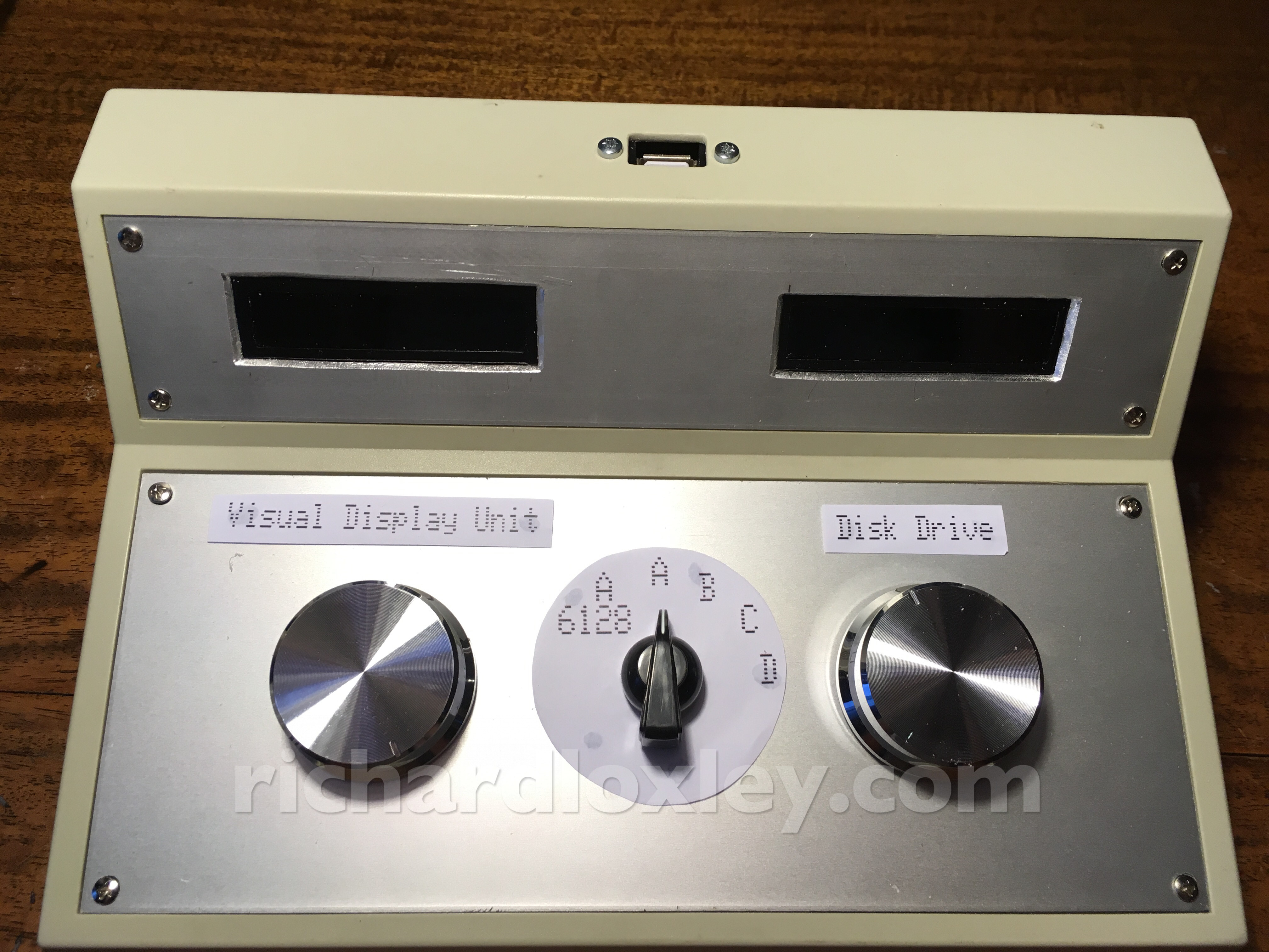
Top
On the top the USB socket for the floppy disk emulation. (And the control panels I made previously.)
The only hardware jobs left to do are:
- wire up the floppy ports
- wire up the power switch and power socket
- wire up the drive selection switch
Then the only remaining improvements are in the software ![]()