I’m in the final straight of the Retro Challenge, so trying to get all the components of my RetroMatic 2000 to come together in one package.
As a reminder, the RetroMatic 2000 comprises:
- a video converter board to convert 288p hybrid video from an 8-bit micro to VGA
- an Arduino to re-program the TV5725 chip on the video board to correctly handle 288p
- a sync-stripper to clean up the video input
- a scanline generator to re-create the look of 288p video on the VGA output
- an LCD display and rotary encoder to control all the video parameters
- a Gotek USB floppy emulator (flashed with HxC firmware) to emulate a Shugart 34 pin floppy (as used by 8-bit micros)
- an LCD display for the Gotek
- a rotary encoder (via the Arduino) to control the Gotek more easily
- sound effects (via the Arduino) to emulate the sound of a floppy drive
That’s a lot of components! And most need to connect to the Arduino in one way or another as the Arduino is the brains that controls everything and provides all the UI.
I’m using an clone of an Arduino Nano (that’s what I had lying around), which has the following pin specifications:
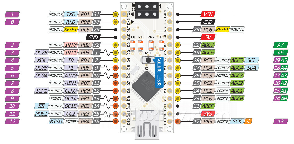
The Nano has 11 general digital IO pins (D2-D12) which can be used for digital input or output. Five of them can be used for analogue (PWM) output instead.
It has 3 further slightly limited digital IO pins: D0 (RX) and D1 (TX) are also used for the USB serial port, and D13 is connected to an on-board LED via a resistor which can affect its use as an input unless care is taken.
It also has 6 general analogue pins (A0-A5) which can be used either as extra digital input or output, or can be connected (in turn) to the single analogue to digital converter (ADC).
Finally it has two extra analogue pins (A6 and A7) which aren’t present on all Arduino boards. These can only be used as extra analogue inputs (they are connected to the remaining 2 ports on the ADC multiplexer).
So time to do an audit of my requirements:
Analogue (PWM) output (1 pin)
- speaker
Digital output (11 pins)
- Gotek button A
- Gotek button B
- scanlines on
- scanlines wide/narrow
- scanlines resolution
- LCD enable
- LCD RS
- LCD D4
- LCD D5
- LCD D6
- LCD D7
Digital input/output (2 pins)
- i2c SCL
- i2c SDA
Digital input (7 or 8 pins)
- rotary encoder 1a
- rotary encoder 1b
- rotary encoder 1 click button
- rotary encoder 2a
- rotary encoder 2b
- head step
- drive active
- motor active (optional)
That’s a lot of pins! 21 or 22 to be precise.
My Arduino Nano has only 17 regular pins, although I can safely use the LED pin D13 as an output, bringing me up to 18.
Adding in the two serial pins brings me up to 20 pins (although it means I have to unplug whatever’s attached to it during programming, unless they are normally-open switches).
That’s still one or two short. I guess I’m going to have to use those extra analogue input pins. But I don’t actually need any analogue inputs. I only need digital inputs, so I’ll feed the digital signal into the ADC, and just look for a signal that’s higher than 512 (out of the 1023 maximum level from the 10 bit ADC).
The only problem is that using analogRead() is really slow – as it has to do thousands of samples on the input. A single call to analogRead() takes about 115μs, whereas a digitalRead() takes 4μs (and direct port access to the digital pins is an order of magnitude even faster at 0.3μs).
So let’s see if we can speed things up at all. We don’t care about the thousands of samples, or the accuracy, as we’re only looking for an on/off signal.
It seems that you cannot change the number of samples the ADC uses – that’s hard-coded. However you can change the frequency of the sampling. It’s derived by a ‘prescaler’ factor that divides the CPU clock to get the ADC sampling rate. By specifying a higher multiplier, the designated number of samples are achieved in fewer clock samples. [Reference 1, reference 2].
I used the following code (derived from reference 2 above):
    // set ADC set prescale to 16
    #define cbi(sfr, bit) (_SFR_BYTE(sfr) &= ~_BV(bit))
    #define sbi(sfr, bit) (_SFR_BYTE(sfr) |= _BV(bit))
    sbi(ADCSRA,ADPS2);
    cbi(ADCSRA,ADPS1);
    cbi(ADCSRA,ADPS0);
In my tests, by running this code at the start of the program, analogRead() is reduced from 115μs to only 15μs! It’s still not as good as the 4μs from digitalRead(), but now it’s only 4 times slower, rather than 30 times slower.
I still need to avoid using A6 and A7 for signals that need the extra speed of direct port access, so that eliminates the rotary encoders (in interrupt handlers) or the drive-select and head-step signals (my last post showed how I needed direct port access to make them work).
That only leaves two inputs that I could possibly use on A6 and A7:
- rotary encoder 1 click button
- motor active (optional)
Both are slow enough actions (user input, and drive motor spin-up taking several seconds) that the slightly slower access should be fine.
But that means I can’t use the normally-open switch on the rotary encoder 1 click button to go on RX or TX. I’ll put the drive signals on those pins. Those are only used to trigger the sound effects, so I’ll have to just disconnect those pins during re-programming (if I forget to reattach them all I’ll lose is the sounds).
So here’s my final (fully populated!) pin out:
#define PIN_HEAD_STEP            1 // TX (no serial, disconnect during flash!)
#define PIN_DRIVE_SELECT         0 // RX (no serial, disconnect during flash!)
//                               reset
//                               ground
#define PIN_ENCODER_1_A          2
#define PIN_ENCODER_1_B          3
#define PIN_ENCODER_2_A          4
#define PIN_ENCODER_2_B          5
#define PIN_SPEAKER              6 // needs to be PWM
#define PIN_LCD_RS               7
#define PIN_LCD_ENABLE           8
#define PIN_LCD_DATA_4           9
#define PIN_LCD_DATA_5           10
#define PIN_LCD_DATA_6           11
#define PIN_LCD_DATA_7           12

//                               vin
//                               ground
//                               reset
//                               5v
#define PIN_ENCODER_1_CLICK      A7 // analogue input only (hack ADC frequency)
#define PIN_DRIVE_MOTOR          A6 // analogue input only (hack ADC frequency)
#define PIN_SCANLINE_ACTIVATE    A5
#define PIN_SCANLINE_WIDTH       A4
#define PIN_HXC_BUTTON_LEFT      A3
#define PIN_HXC_BUTTON_RIGHT     A2
#define PIN_I2C_SDA              A1
#define PIN_I2C_SCL              A0
//                               ref
//                               3.3v
#define PIN_SCANLINE_RESOLUTION  13
I also selected the layout for best access to the pins that will be connected to strips on my veroboard layout. It’s a bit of a shame that PIN_ENCODER_1_CLICK on A7 is separate from the other encoder 1 lines on the other side of the chip. That means I’ll have to separate the ribbon cable connecting it to the board. But hey, working under such limitations something has to give!
I’ve tested out this pin layout (still on a breadboard), and here’s my first test of almost everything working together (video converter, floppy emulator, Arduino, two LCD displays, two rotary encoders to control them, and disk sound effects). The only things still to connect up are the scanline generator and the sync splitter.
(Turn up the volume to hear the disk sound effects).