This is part of a series of posts for the Retro Challenge 2018/04. See my index page for the other posts.
First off, I decided to have a look inside my newly acquired Osborne to see what I had in store.
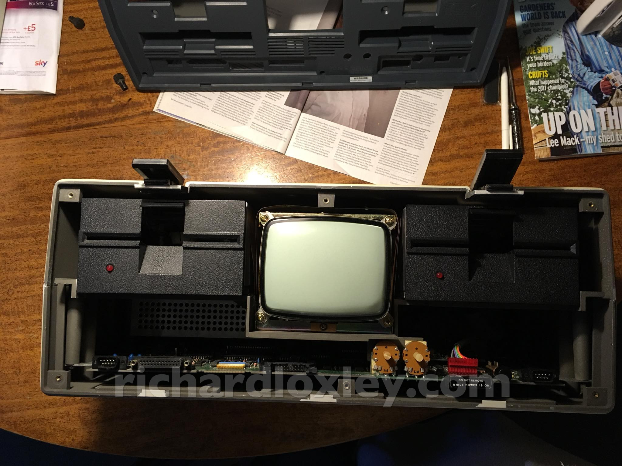
The front cover comes off easily after removing the monitor brightness/contrast knobs and a few screws:
Good news: that daughter board at the back (with the grey floppy cable coming out of it) means it’s had the Double Density controller fitted:
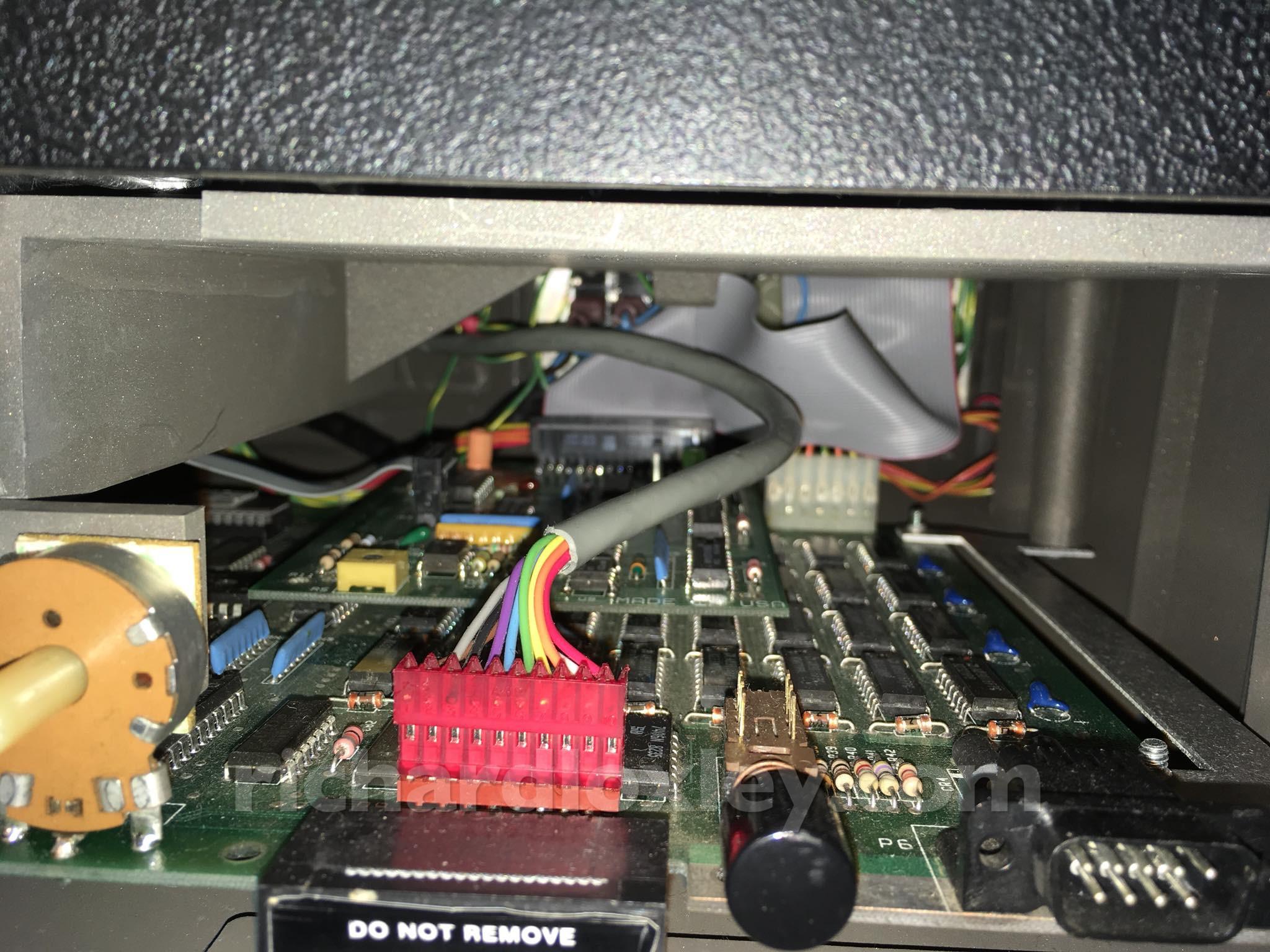
Apparently most had, apart from very early models (and mine is the later 1a with the catches on the top rather than the sides).
This means I can use higher capacity floppies (200KB rather than 100KB). And the boot floppy images I’ve found online are DD, so I can use them ?
The motherboard end is a standard 34 pin connector, so I can wire up a floppy drive cable to work with my emulator.
However the drive end uses circuit board edge connectors, so my initial thought was I wouldn’t be able to connect a physical drive and an emulator at the same time (to write a physical disk from my disk image) without hacking up a vintage cable, which I’m slightly loath to do…
But then, I realised there is a way to make the cables work.
I have both male and female 34 pin floppy connectors and 34 way ribbon cables.
I can write up an extension cable, male to female straight through, to go between the motherboard and the custom Osborne floppy cable. Then add a third connector to the extension with the wires rearranged to be Shugart standard wiring.
Then I can connect a standard floppy cable going to a standard Shugart drive (or emulator) on that third connector. The extension cable can be removed to return the computer to its original state at any time.
Sweet ?
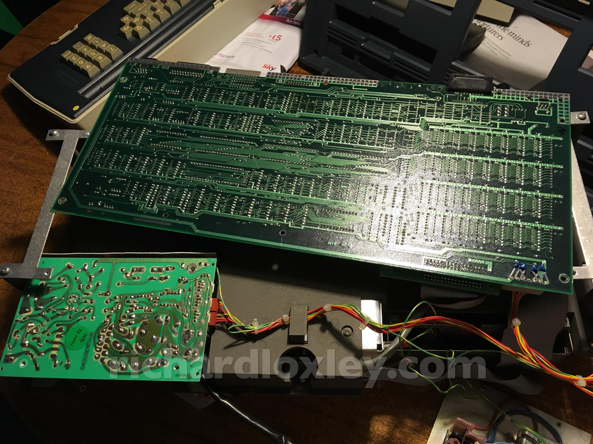
Next, removing the bottom of the case. A very neat motherboard:
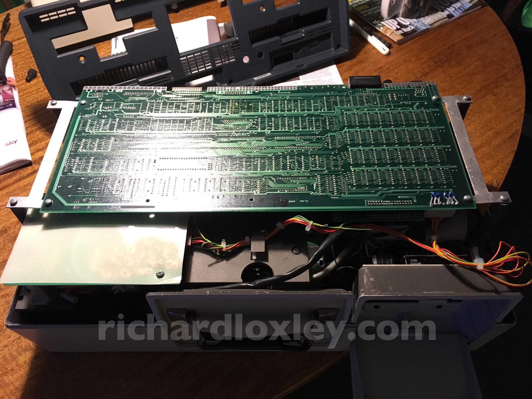
I removed everything from the case, and unscrewed the motherboard so I can check the power supply (bottom left):
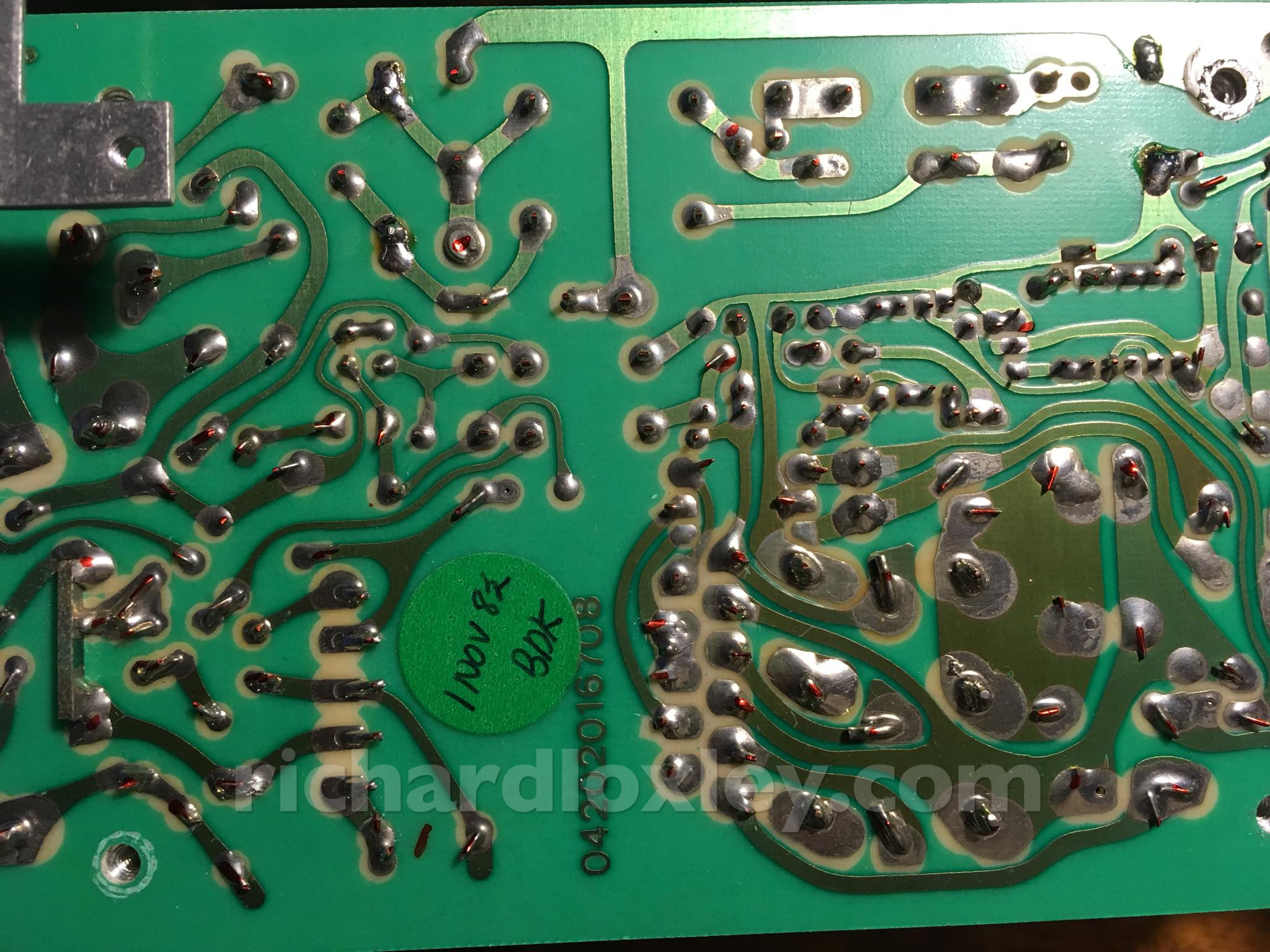
The PSU has a manufacture date of November 1982.
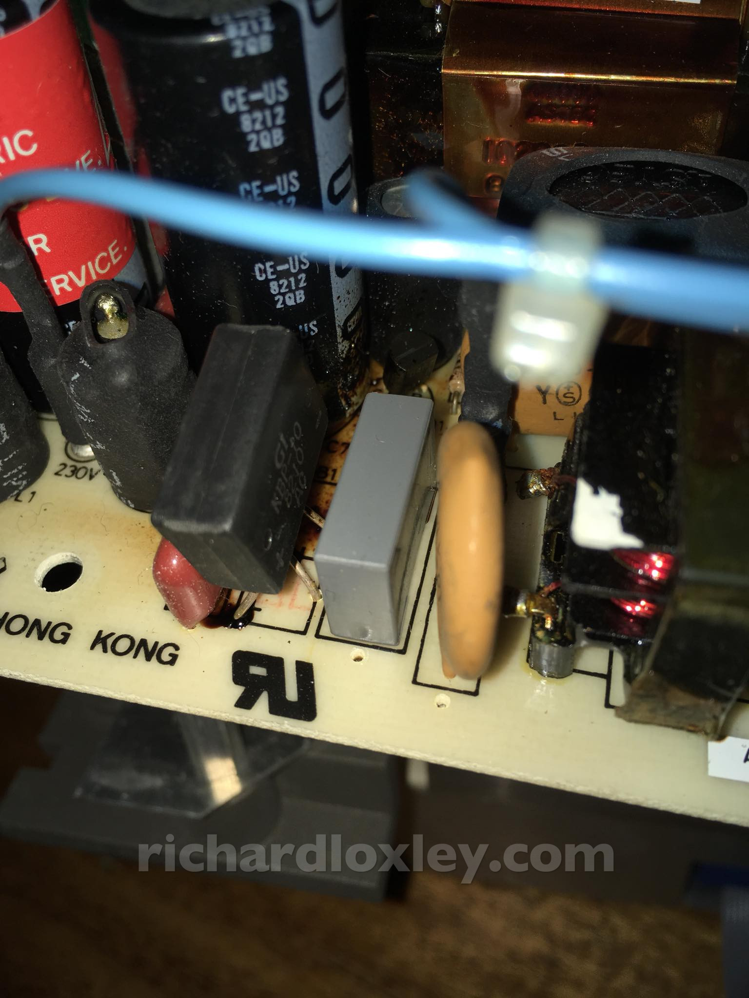
The power supply. Looking for dodgy capacitors:
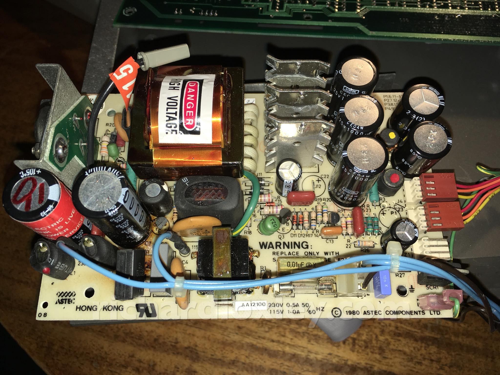
Bingo! This one is very cracked indeed. I wonder if it’s already let the magic smoke out (usually they just filter the mains, so a failed one won’t always stop it powering on).
Either way I’m not going to power it on again until I’ve replaced that.
It’s basically the same as the PSU in the BBC Micro that I already fixed. Except this one is much easier to get to.
I’d better order some capacitors. I gather the TRS-80 Model 3 also has the same type of PSU, so I should order some spares too.
(In the end it was cheaper to buy a 5-pack of BBC capacitor repair kits from eBay than buy the individual components from RS.)
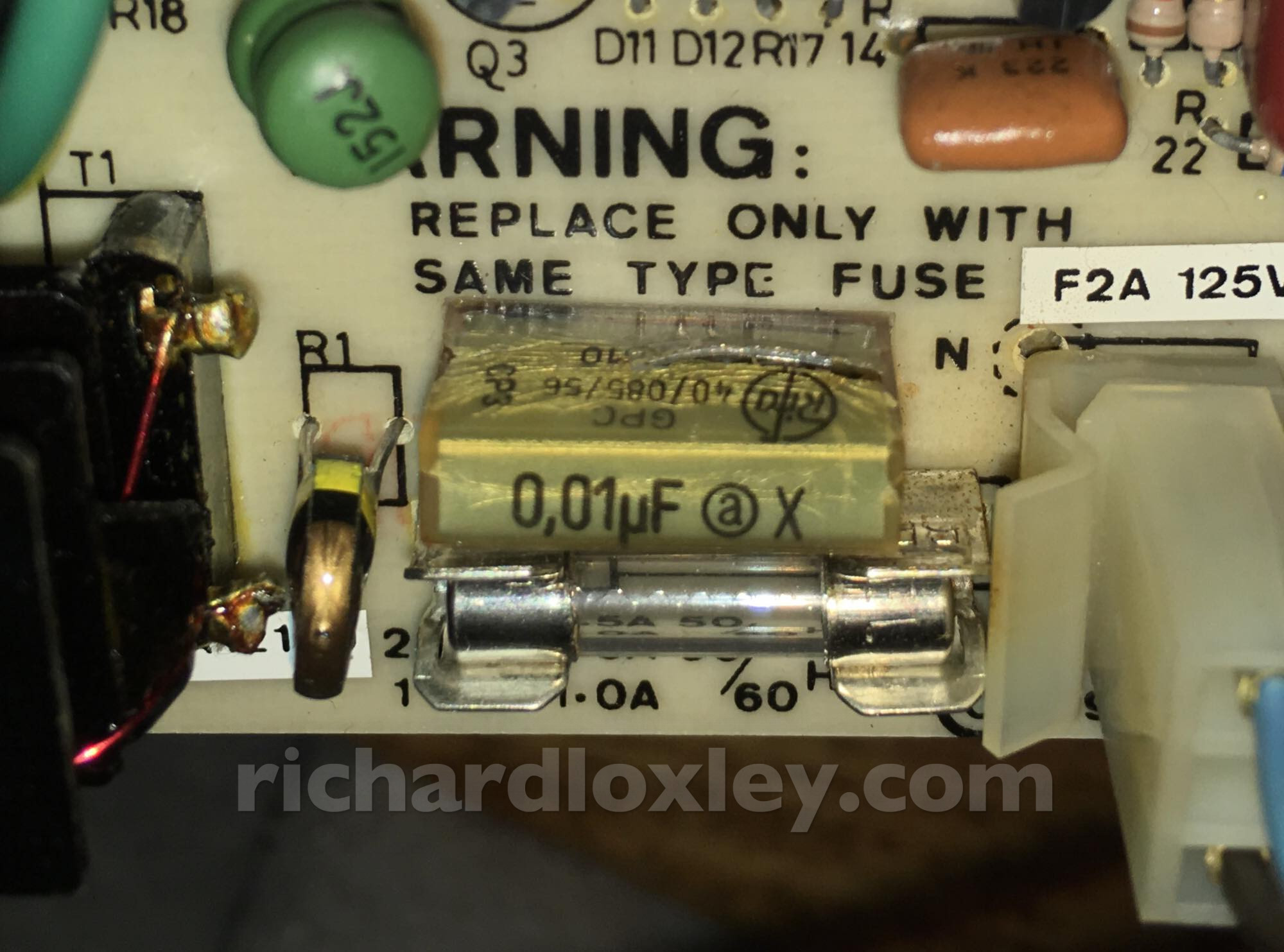
It’s also cracked on the other side:
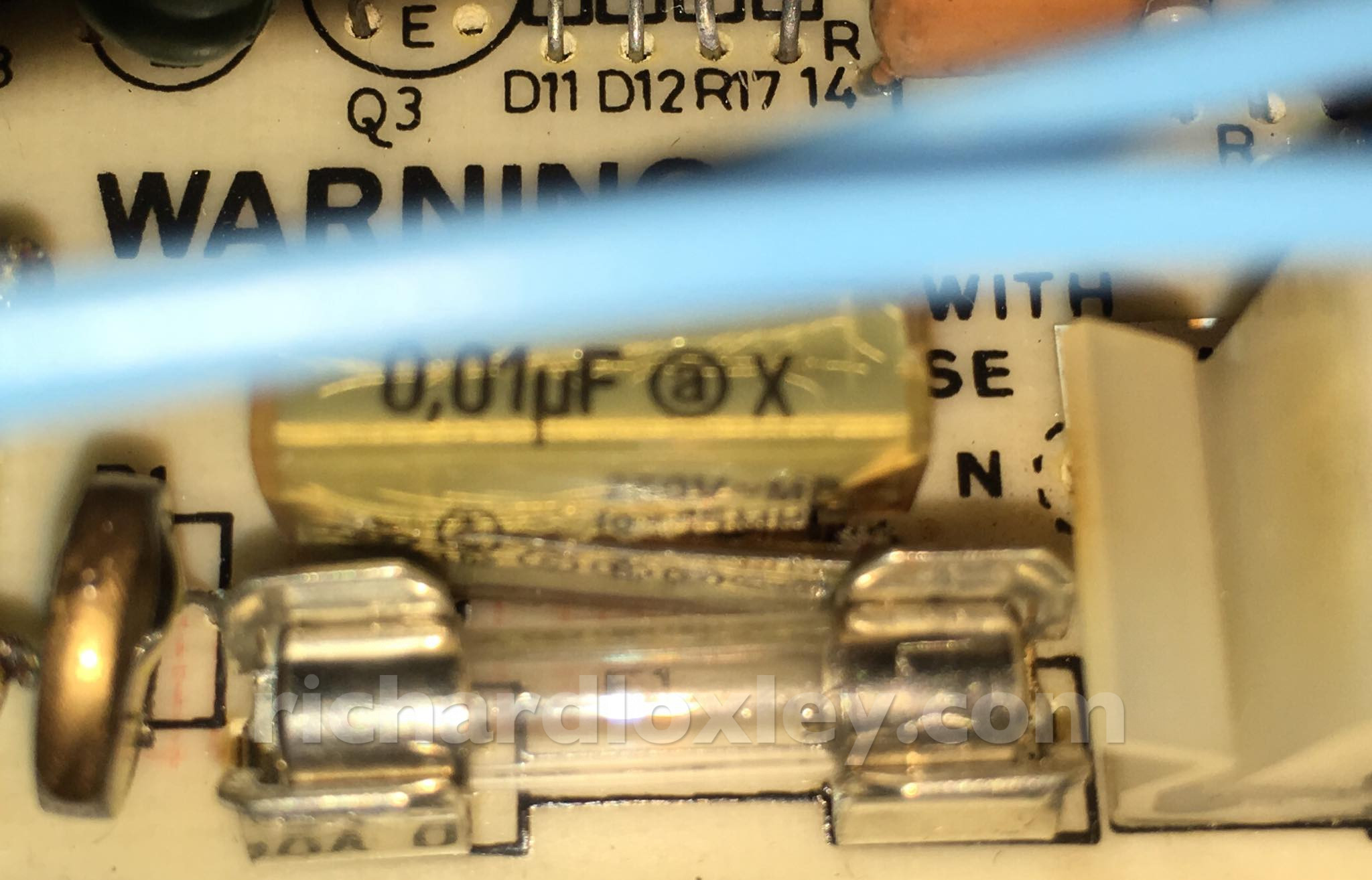
These capacitors seem different and no sign of cracking. But is that just because they have plastic casings? I’d better read up about it (although there’s much less info about these compared to the BBC):
This is what it would originally have looked like:
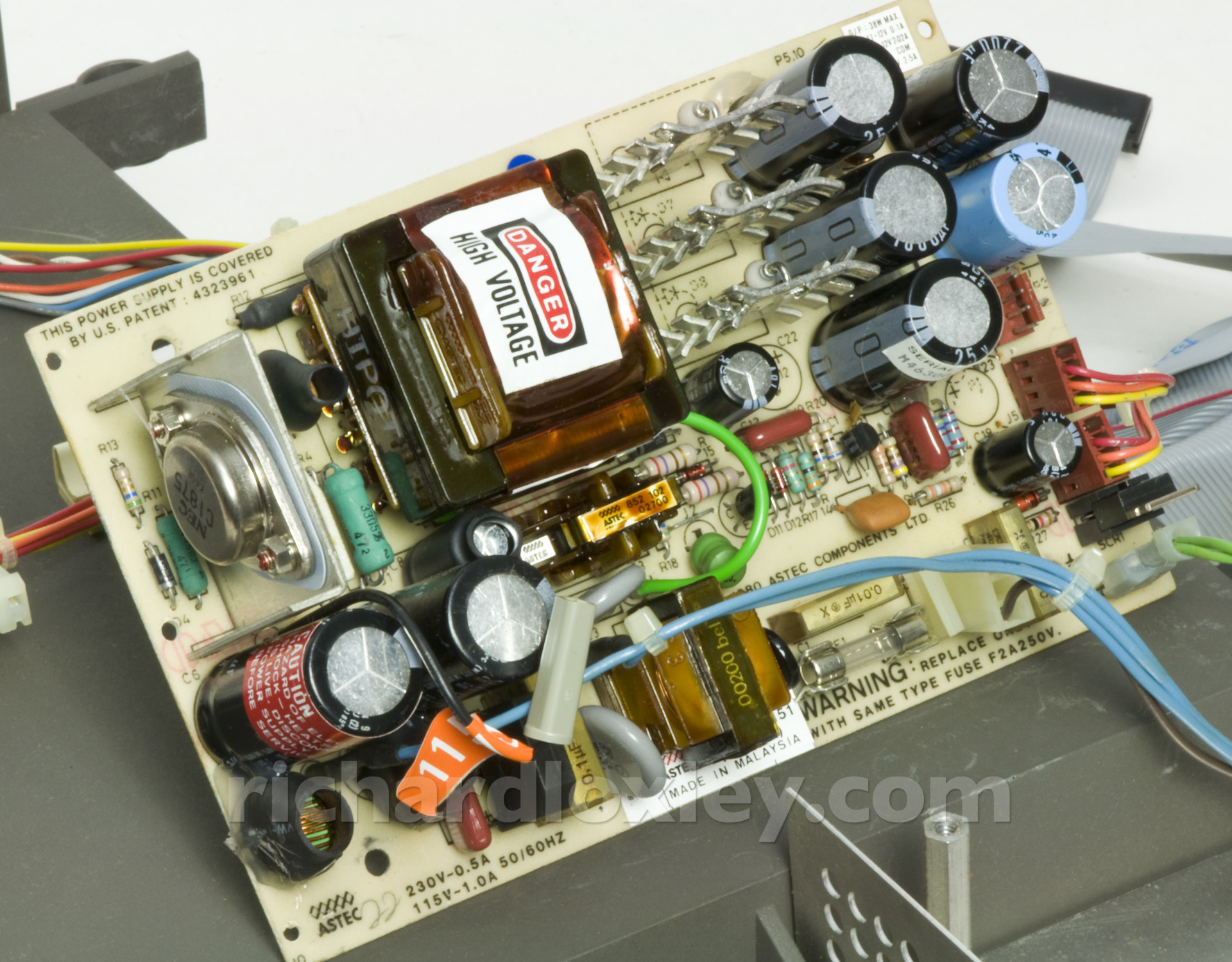
Which interestingly shows another paper film X capacitor to the right of the light blue wire connector … which matches up with some re-soldering on my board!
So it seems it originally had 3 such capacitors, and someone’s replaced 2 of them and left the third. Lazy job!
Looking at the electrolytic capacitors, this one is not looking good:
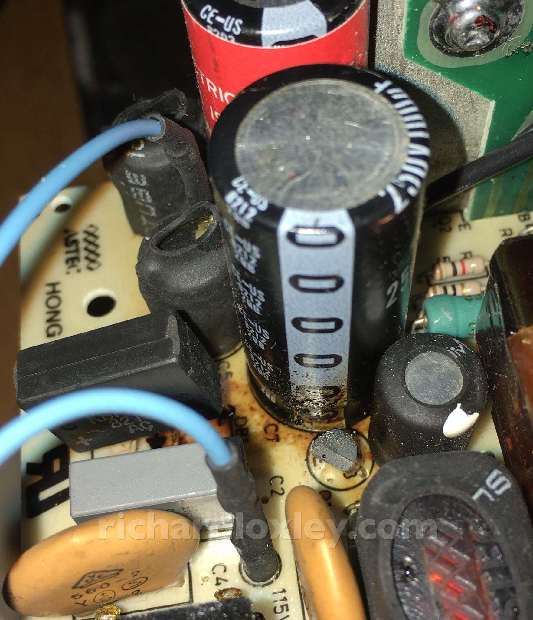
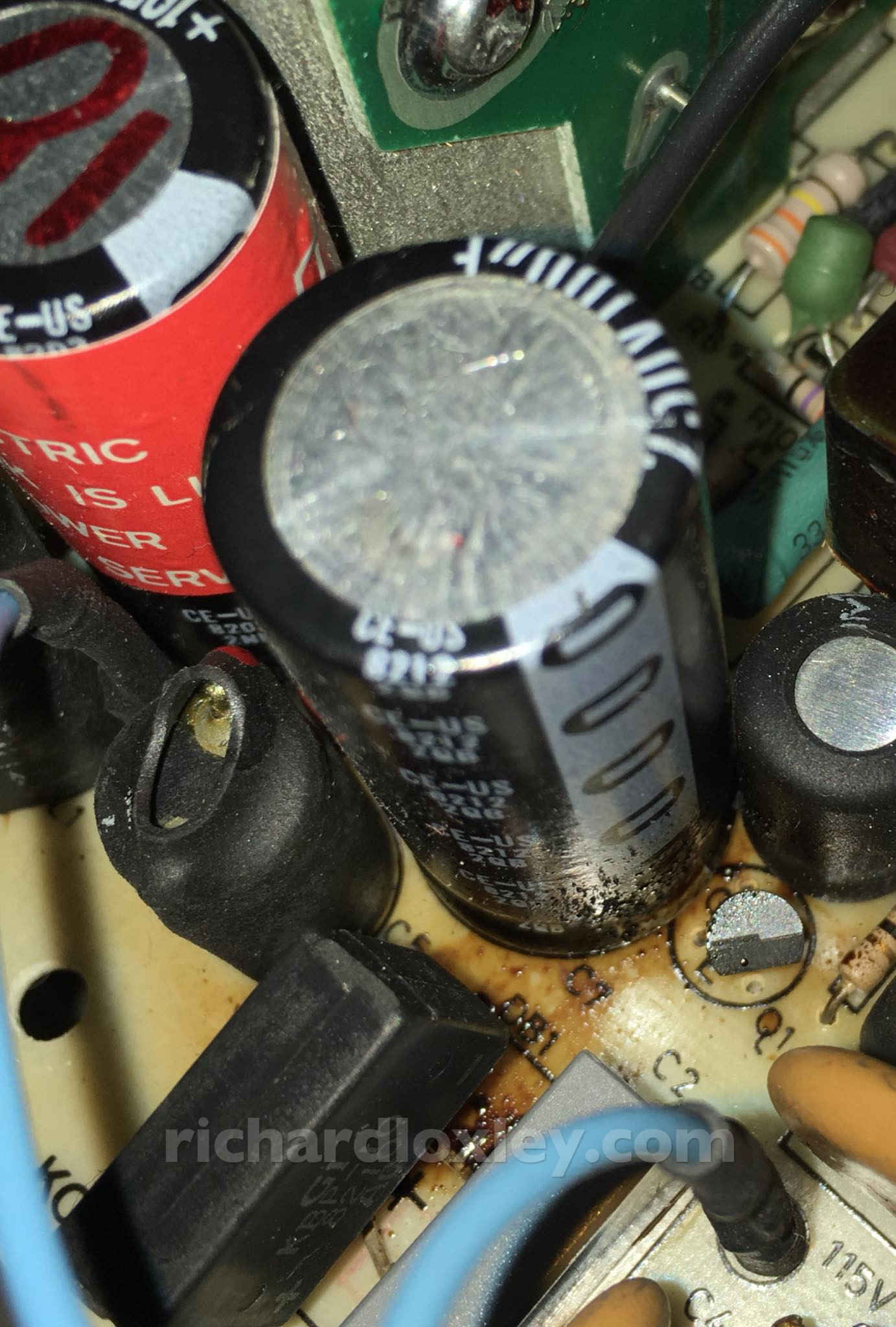
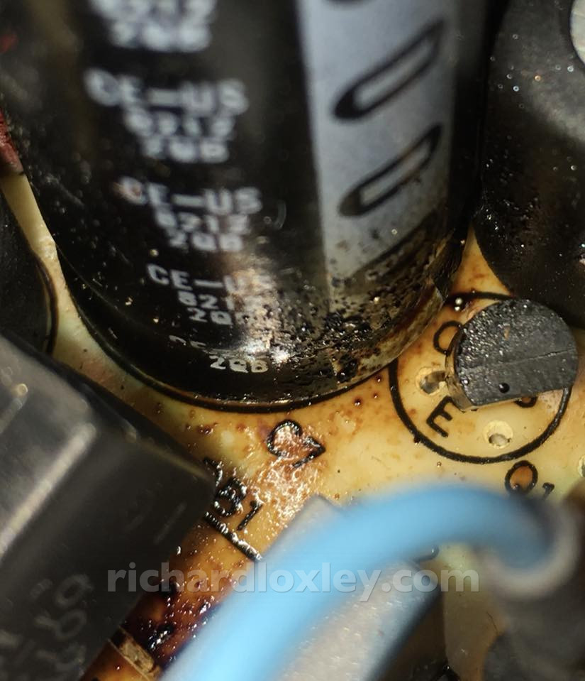
Definite signs of electrolyte staining on the circuit board, and on the lower section of the capacitor.
However the stain extends towards the replaced capacitor, and the residue on the side is only on the side facing the replaced capacitor (the light grey rectangular one bottom left). Is it just residue from the exploded X capacitor? Or is the electrolytic capacitor on its way out too? There’s no sign of bulging that I can see.
This thread shows similar staining from a failed X capacitor on a similar PSU.
It would cost me £2 – £3 to replace this one too, and it would probably arrive about the same time as the others. Maybe it’s worth it for the peace of mind?