This is part of a series of posts for the Retro Challenge 2018/04. See my index page for the other posts.
I have no boot disks for this Osborne 1. The plan was to connect my USB floppy drive emulator to the motherboard, and boot from that.
My floppy emulator uses the HxC firmware on Gotek hardware.
The author of the HxC firmware managed to get dedicated HxC hardware to work with an Osborne 1.
As a follow-up to that thread, “redrum69” got the HxC/Gotek combination to work with his Osborne 1 (with additional pictures here).
So I looked to be on to a winner!
If only things were that easy…
First to make a drive cable to connect to a Shugart standard floppy drive, rather than the custom Osborne ones. Then I can use my USB floppy emulator.
“redrum69” has successfully done this. I double checked his workings by reading the Osborne technical manual and the original design schematics. I think he made some mistakes (but I see why it would have worked for him).
The Osborne bizarrely labels drive 0 as B and drive 1 as A (that’s confirmed by the schematics)! So the two drive select wires need reversing if the drive letters are to match. Also Osborne power the drives using the data cable, so seven of the ‘ground’ pins are actually 5v or 12v!
And a few data pins contain different signals, but they can be ignored, so those wires need cutting too.
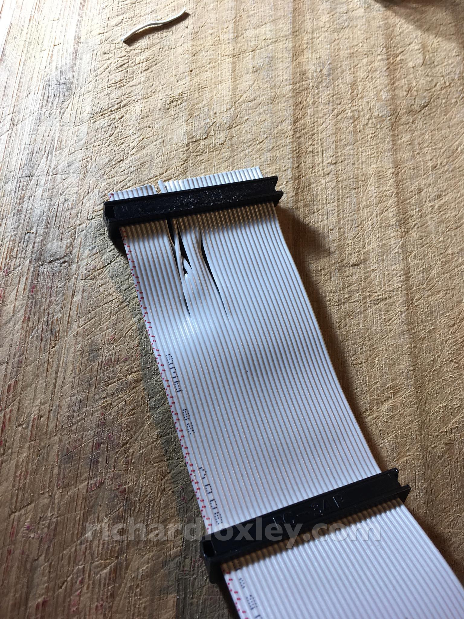
My previous experience with making floppy cables taught me that loose wires are a pain to wire up, so here I’m just swapping the two drive select wires, and then I’ll cut the others after I’ve fixed the socket:
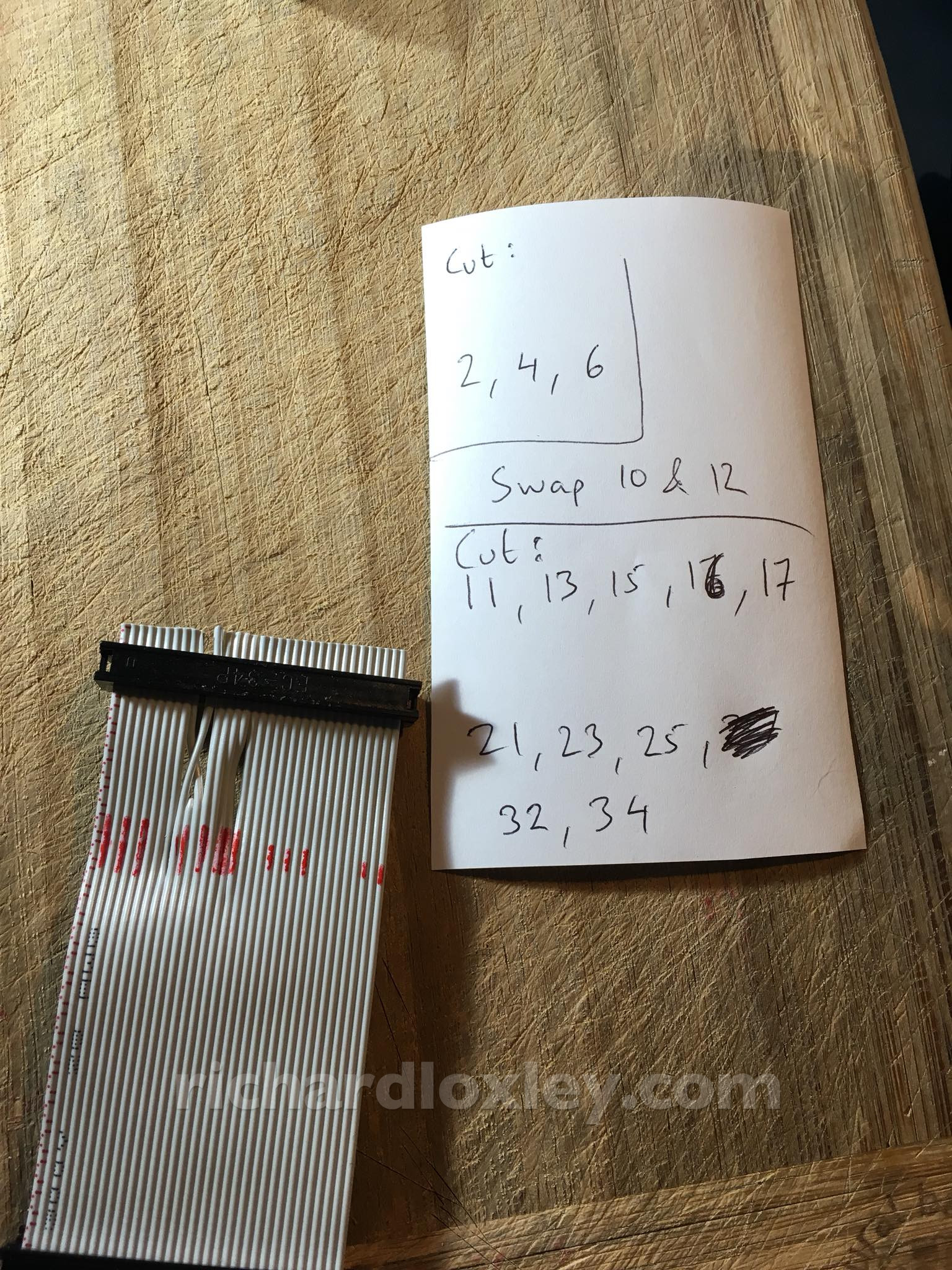
Now marking the wires to cut:
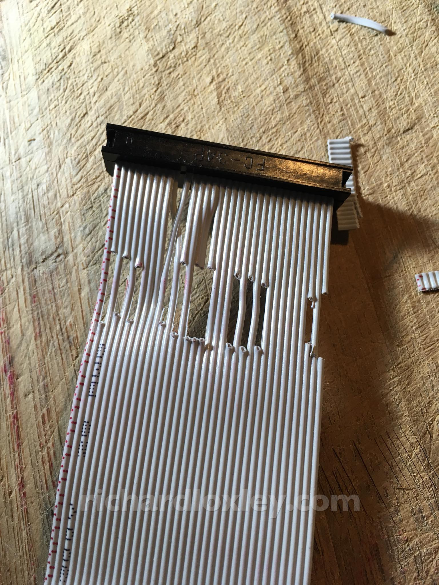
And done. Not pretty, but seems to be correct:
But that’s where the run of success ended. I haven’t managed to get it to boot yet.
At first I couldn’t get it to access my USB drive at all. I eventually decided to fake the drive select signal at the USB end, and then it springs to life. So the drive select signals aren’t getting through.
It might be I got the cable wrong, or it might be something else. Signal pins like that have pull-up resistors to pull them to 5v, and then the equipment pulls it to ground to indicate a signal. Perhaps the Osborne has the pull-up resistors at the drive end rather than the computer end? I’ll investigate that later.
In the meantime I can fake it. But none of the disk images I downloaded will work.
I have the Double Density (DD) expansion board, but a DD image isn’t recognised at all.
I checked the pictures from “redrum69” who’s already done this. His cable is almost identical to mine (I’ll double check the differences aren’t significant later). But I notice he doesn’t have the DD board.
So I download SD images. Not much difference.
I try without the DD board installed (it’s supposed to be backwards compatible with SD disks, but it’s wise to rule it out and do things just like the other guy did). No difference.
Finally I check the disk images he used. They were converted using the same software I used. But his started off as .TD0 image files. Mine were converted from .IMD files. No idea what the formats are, and the conversion software didn’t complain. But I search through my disk images and find some .TD0 images to convert.
More successful. The computer tries to read them, and the emulator correctly steps across the virtual disk (I have a head-step sound wired up). But it still fails to boot from them, either giving boot errors, or just scanning the disk and then ignoring it.
Hmm. It could be the images are wrong in some way (or converted incorrectly). It could be my cable. Or it’s even possible the Osborne disk controller is faulty.
So this is where I’m at now. Stuff everywhere, and nowhere to eat my dinner:
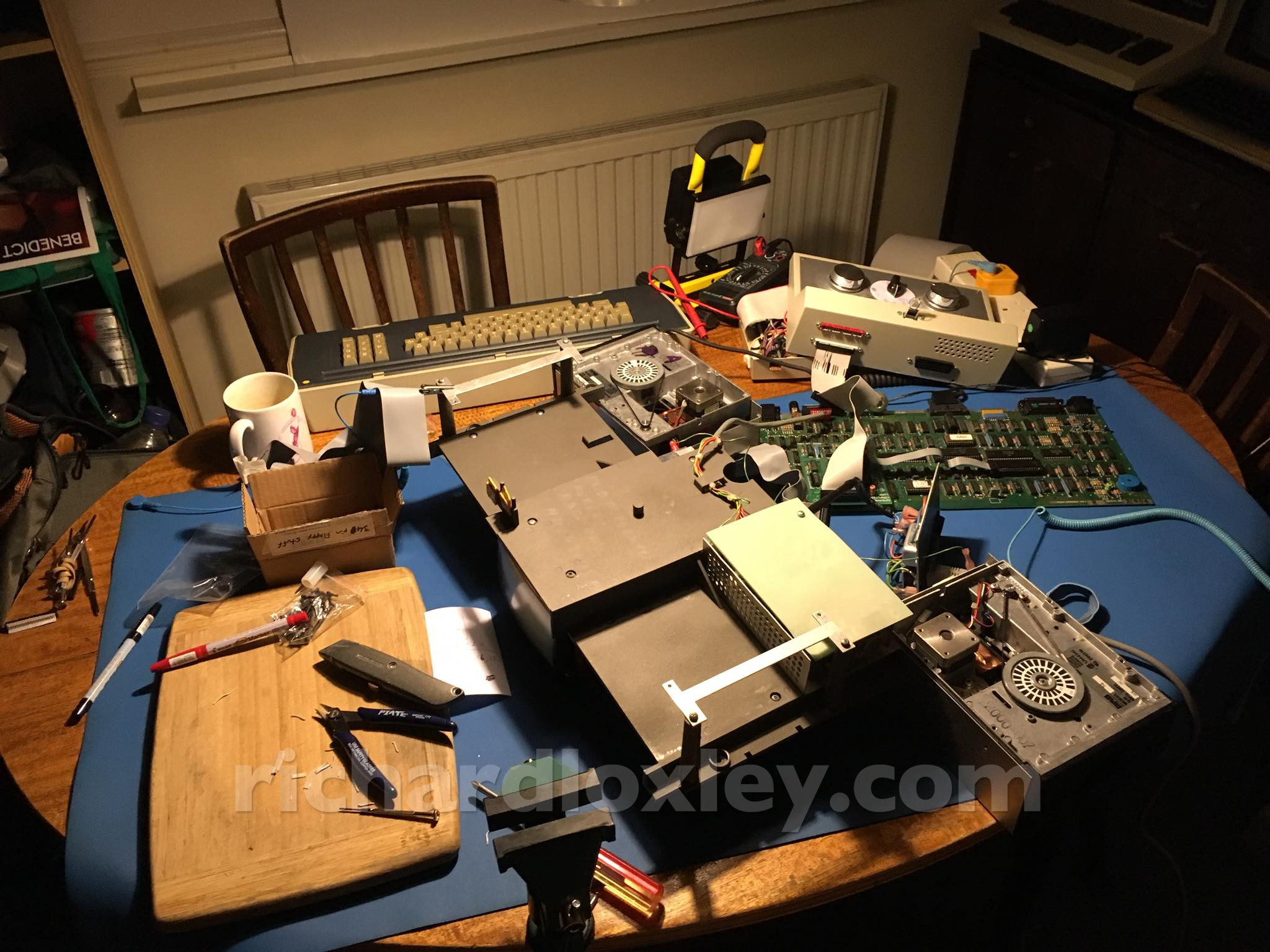
I’ll have to do more investigation tomorrow. An oscilloscope would be useful to check if the signals are getting through. But I’ll have to make do with a multimeter.
Roll on the oscilloscope fund! (So far I’ve got £100 out of £380.) Perhaps I should do a crowd funder ![]()