This is part of a series of posts for the Retro Challenge 2018/04. See my index page for the other posts.
The story so far: I’ve bought two Osborne 1 portable computers (circa 1982) and am trying to get both working.
The first one (henceforth known as the “bad” one) had no boot disks, but would power on to a boot screen. I couldn’t get it to boot from a USB floppy emulator with an appropriate disk image, and when I subsequently obtained genuine boot disks it wouldn’t boot from them either.
The second one (henceforth known as the “good” one) was in much better condition, came with boot disks, and was generally working. I’ve restored it (re-capped the PSU, cleaned the drives, fixed a broken key) and will be trying to get more software running on it.
But I really want to get the “bad” one working again. I hate to see historic technology in that state, and if it’s restored to a working state I can pass it on to another collector. In a non-working state it would be destined for the parts bin :-(
My diagnostics so far:
I managed to get the good Osborne booting from my USB floppy emulator, so I know the emulator, floppy cable and the disk image work.
The bad Osborne gets as far as the boot screen, so I know the Z80 CPU, PSU, screen, and video circuitry on it are working. I also saw slightly strange signals on the floppy cable – but I was using a multimeter as I don’t yet own an oscilloscope so that might be a red herring.
Both Osbornes have the double-density floppy adapter board installed. I did try removing that from the bad Osborne and tried booting from an SD image, which also failed. The good Osborne will boot from that SD image (at least with the backwardly-compatible DD board installed). So that suggests the DD board in the bad Osborne isn’t the problem (or at least, not the only problem).
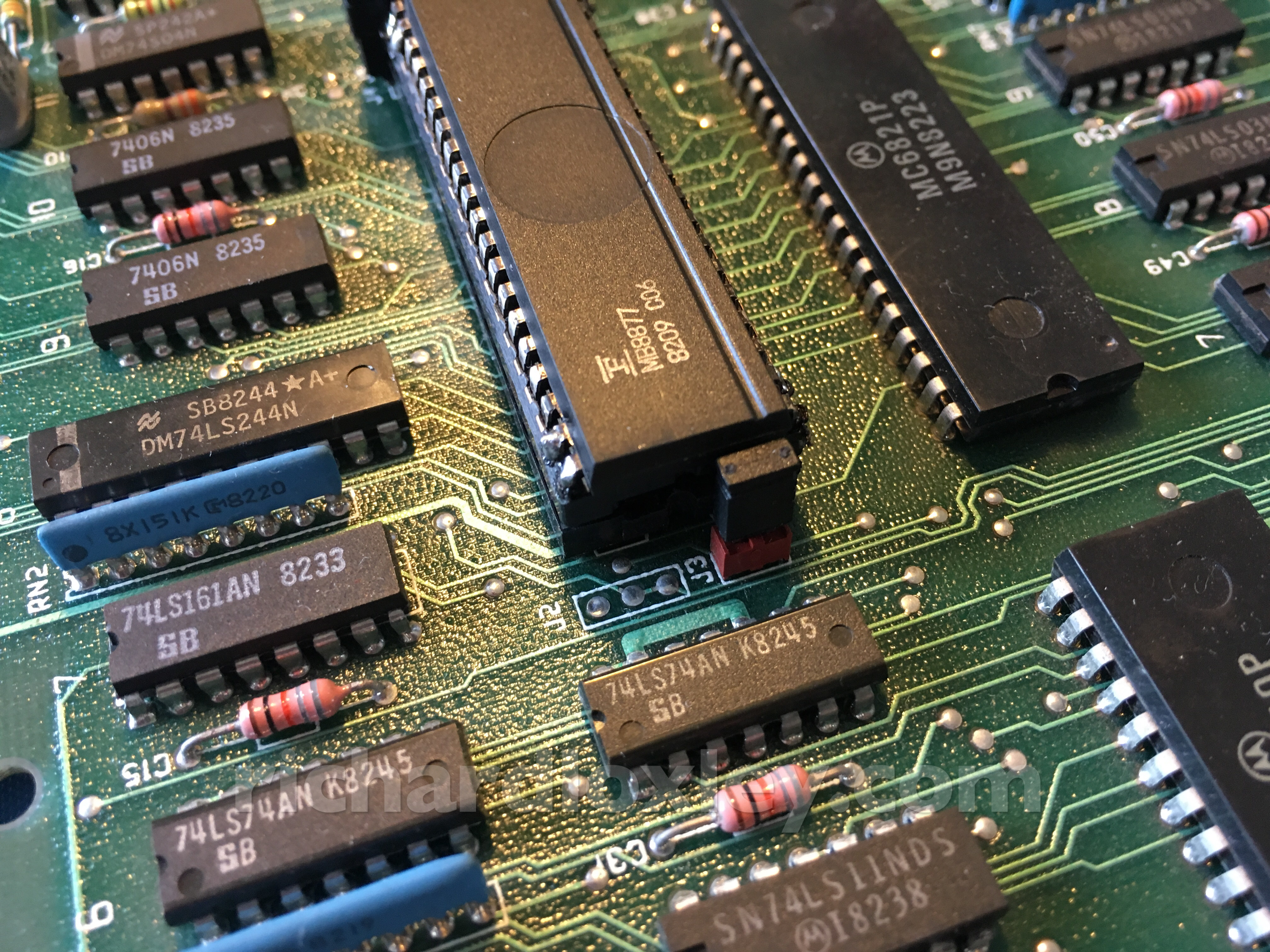
So my next suspicion was the floppy controller. Not only because of the behaviour, but also because the floppy controller chip has had some ‘work’ done on it in the past. It looks like the pins have been broken off so someone tried to solder it into another socket to repair it!
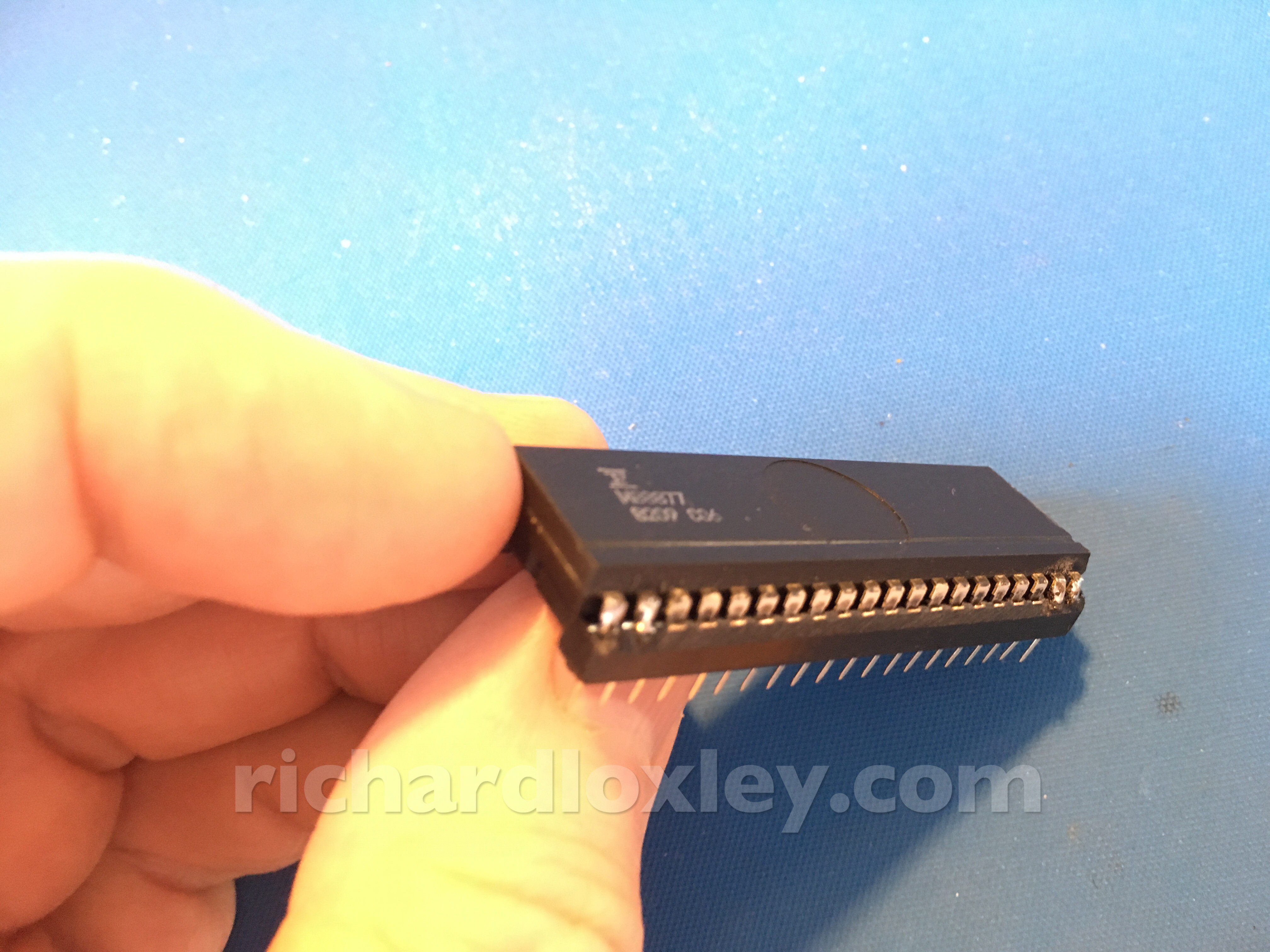
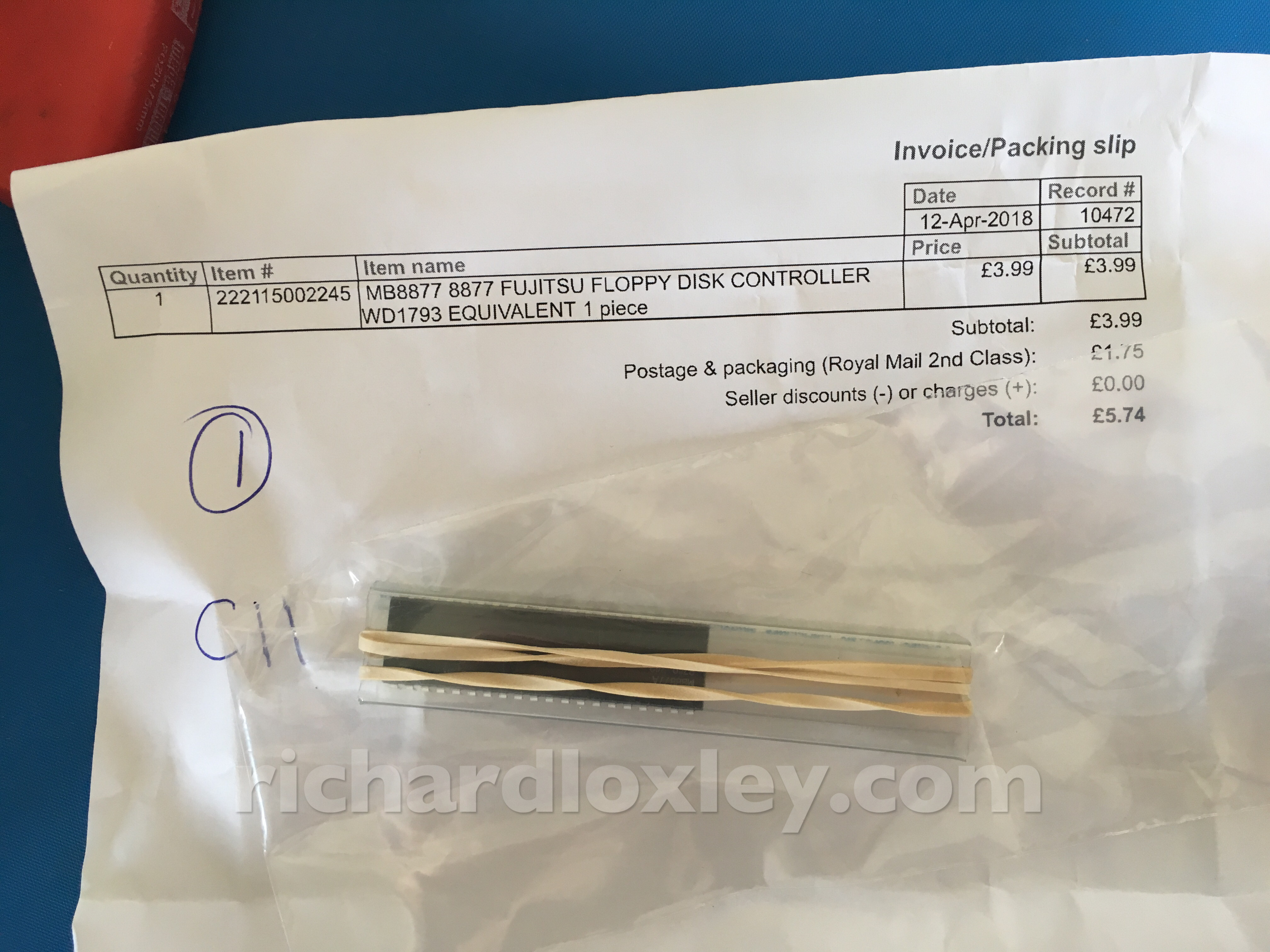
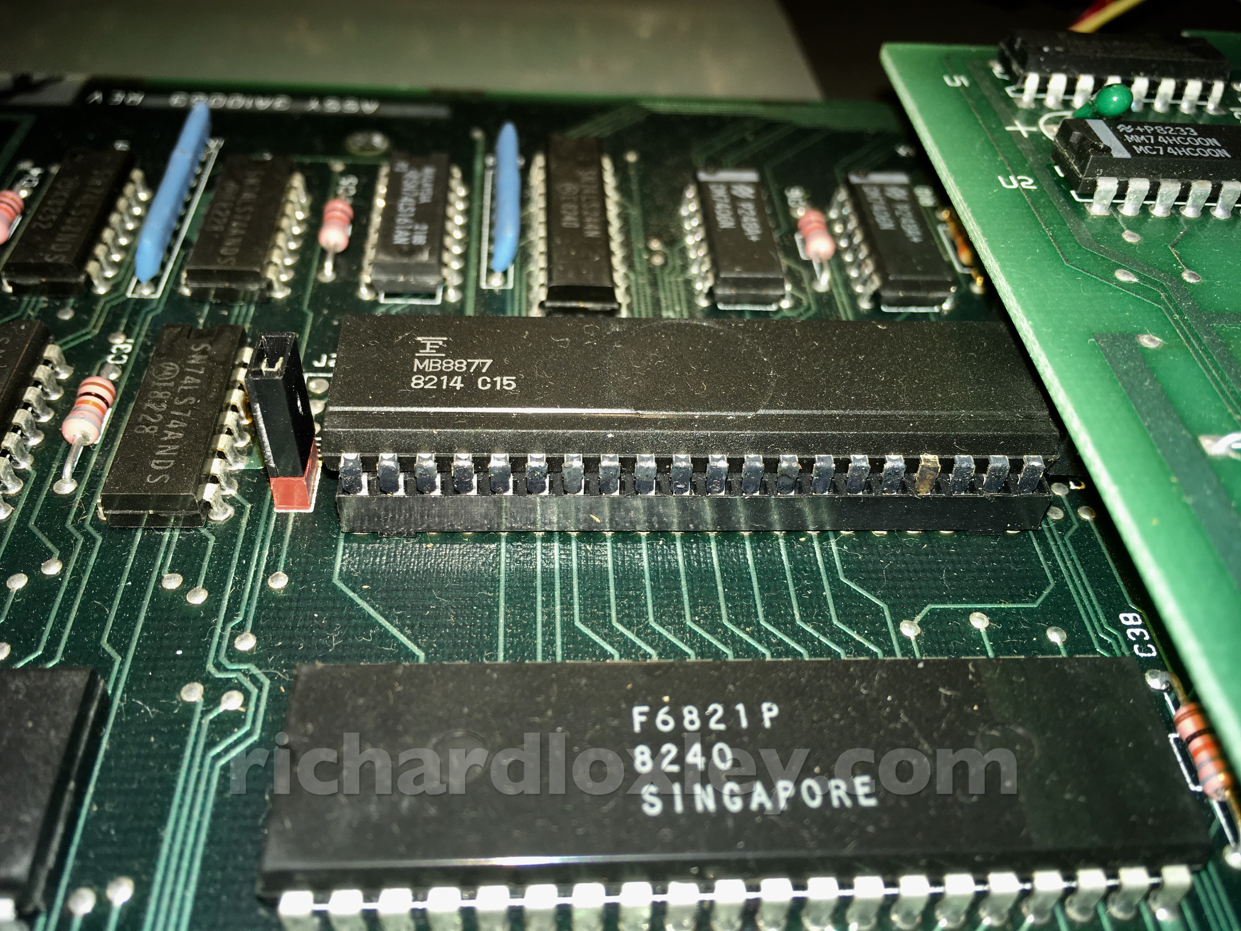
The Osborne uses a standard Fujitsu MB8877 floppy controller chip, and it turns out you can still buy them (from the right eBay seller!) So I ordered one, and waited.
Yesterday it arrived:
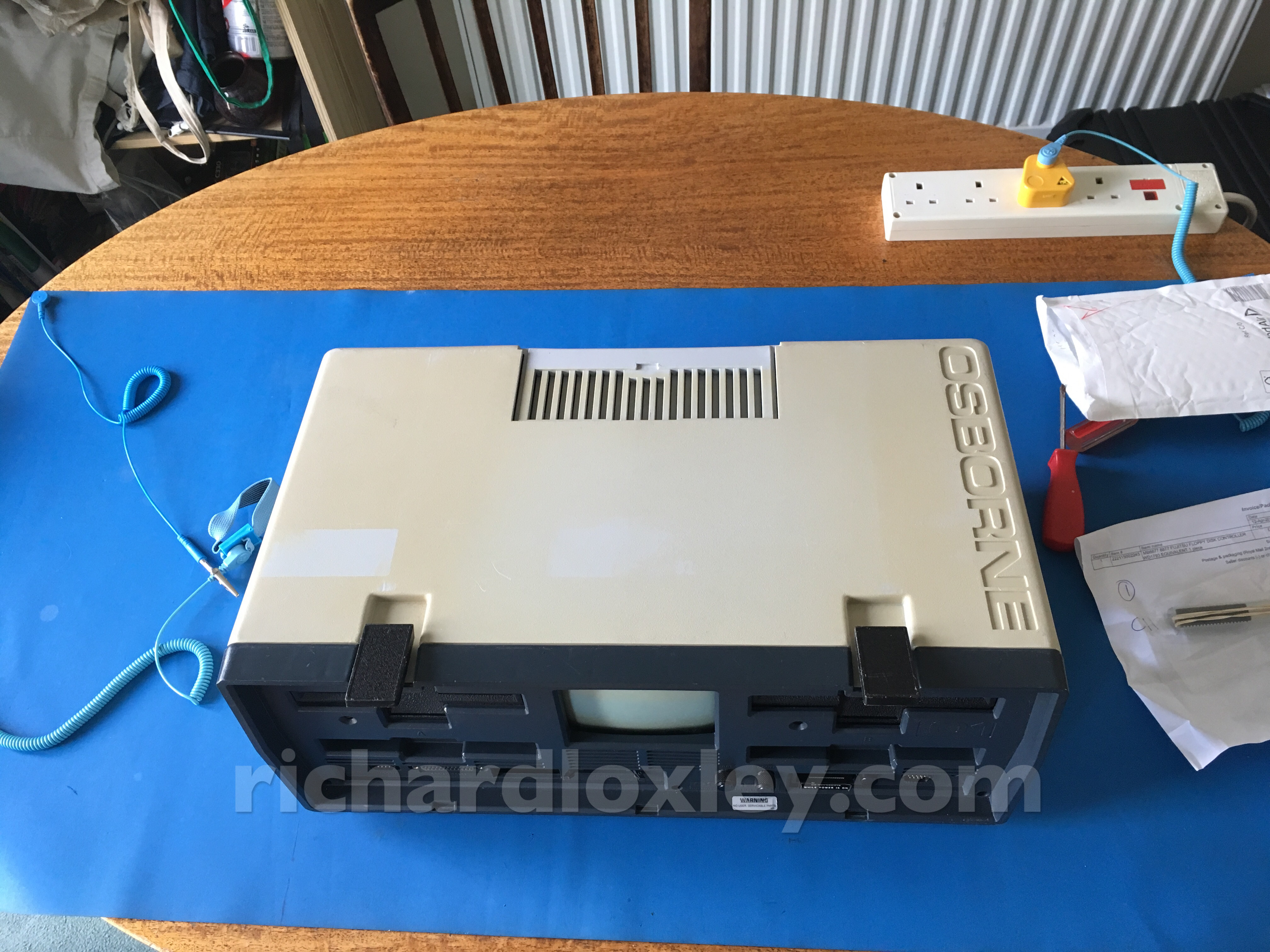
Time to work on the “bad” Osborne again…
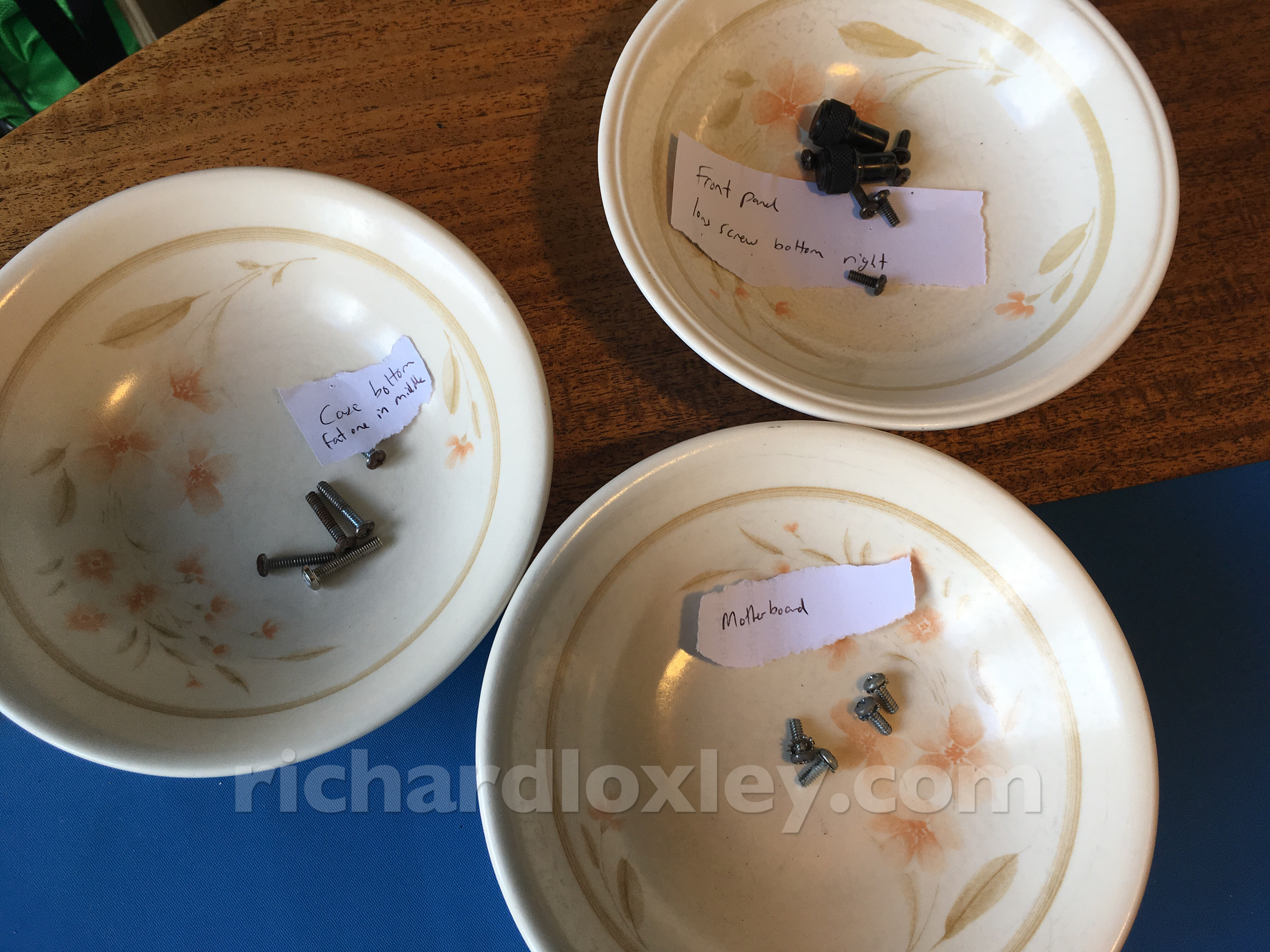
I’ve learned from experience to label my screws as I disassemble equipment :-)
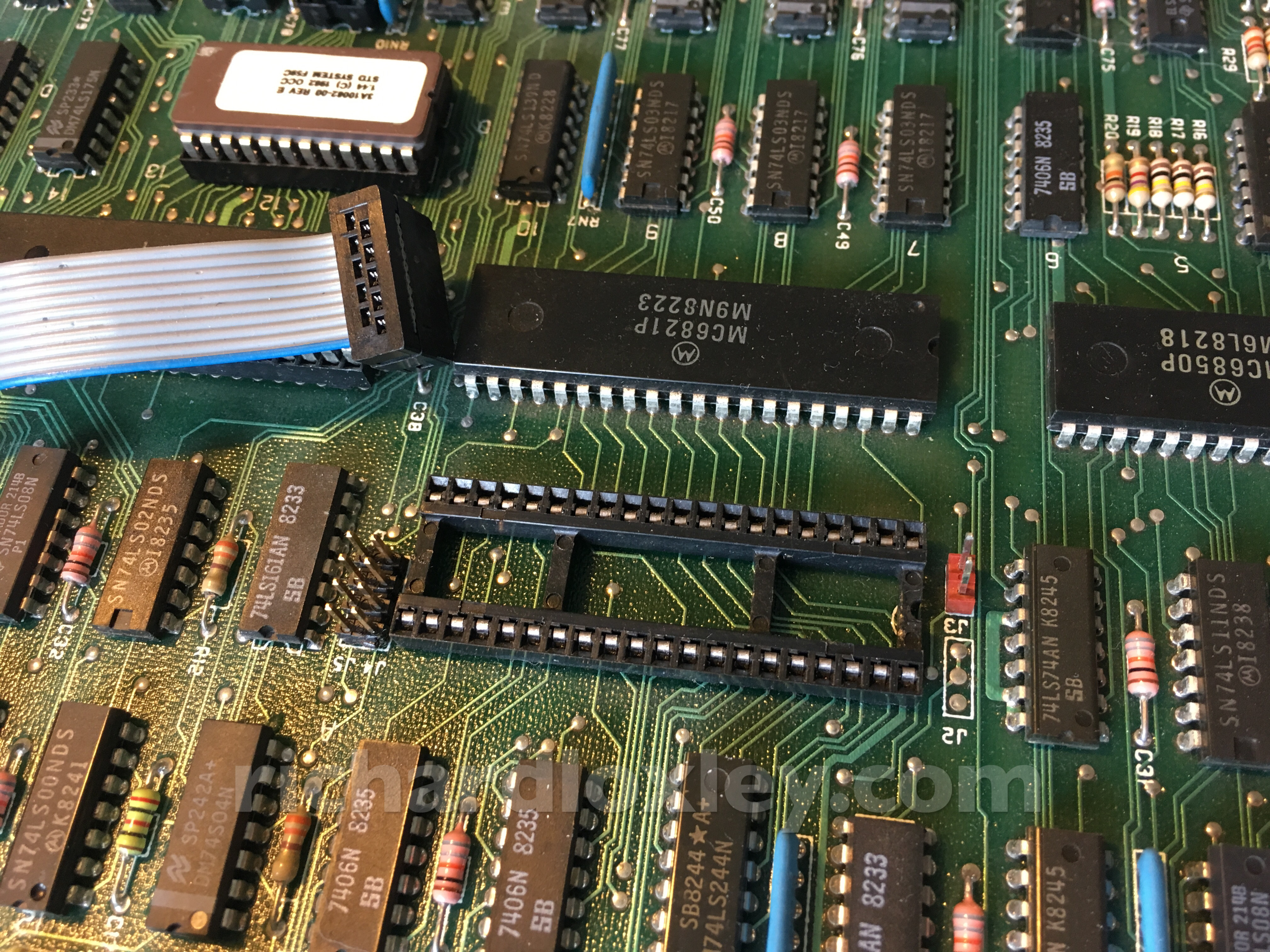
So I go to the floppy controller chip. But wait, what’s that jumper (marked J3) next to the chip? Is that relevant?
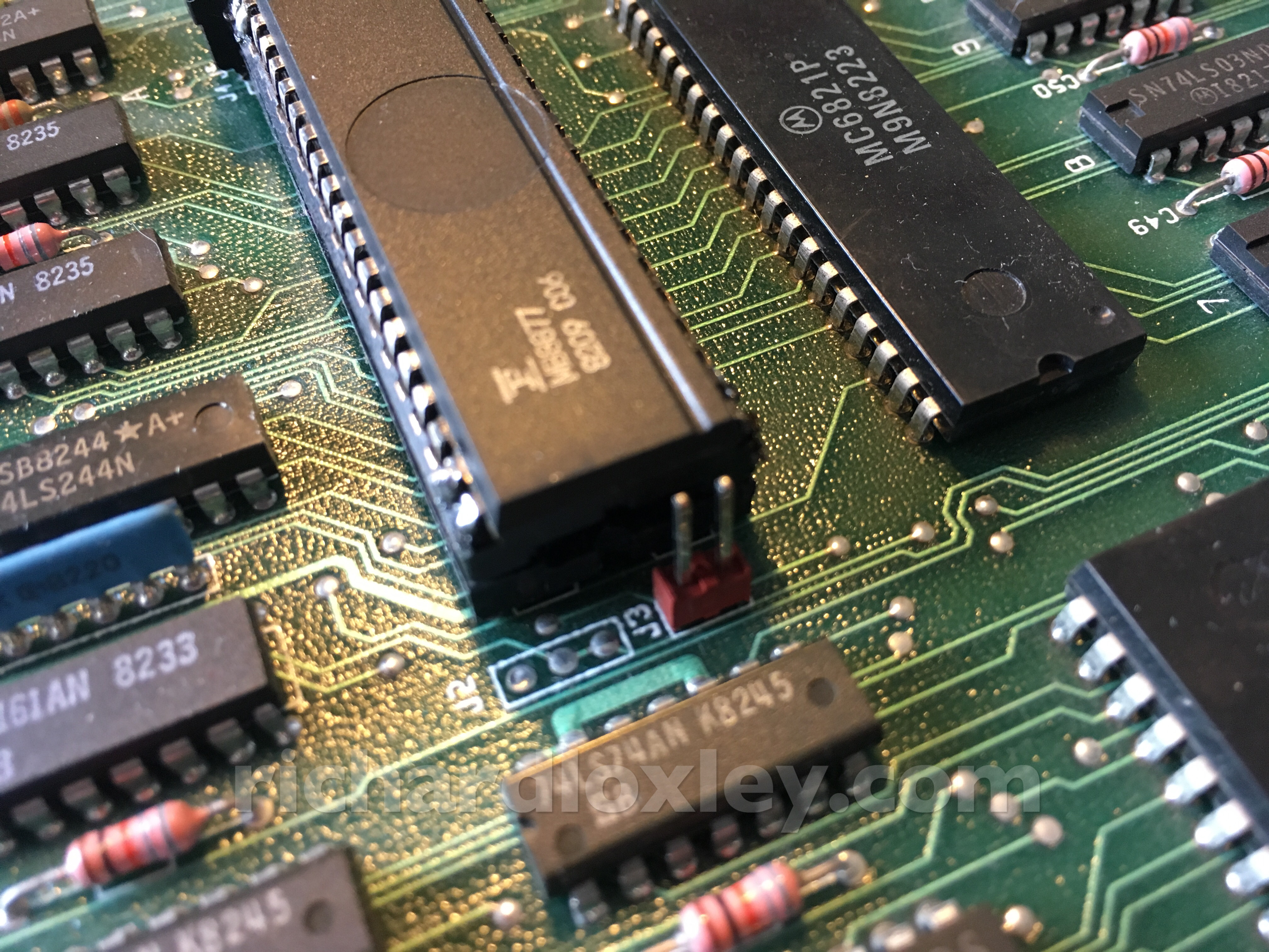
My “good” Osborne is all closed up again, but I flick back through the photos I’ve taken to see if any show that jumper. Bingo!
In the good Osborne that jumper is closed! Now to work out what it is.
No mention in the technical manuals, but eventually I find it mentioned on pages 12/13 of the installation instructions for the double-density (DD) expansion board.
That says for the DD board you must remove jumpers J4 and J5, plug the DD board cable into the pins of J4 and J5, and then close jumper J3.
Because the bad Osborne was missing J3, the DD board won’t work. But removing the DD board won’t work unless J4 and J5 are re-inserted. In short, neither my DD nor SD test would have worked as the jumpers were wrong for both scenarios.
Let’s put a jumper on J3 and try booting from a DD disk image again:
Well this is better, but still not there. Before I’d just get “BOOT ERROR” over and over again. Now I get lots of head-seeking in a repetitive cycle (as if trying to re-read after read failures) and finally after a few cycles of that, the message: “Bdos Err On C: Bad Sector”.
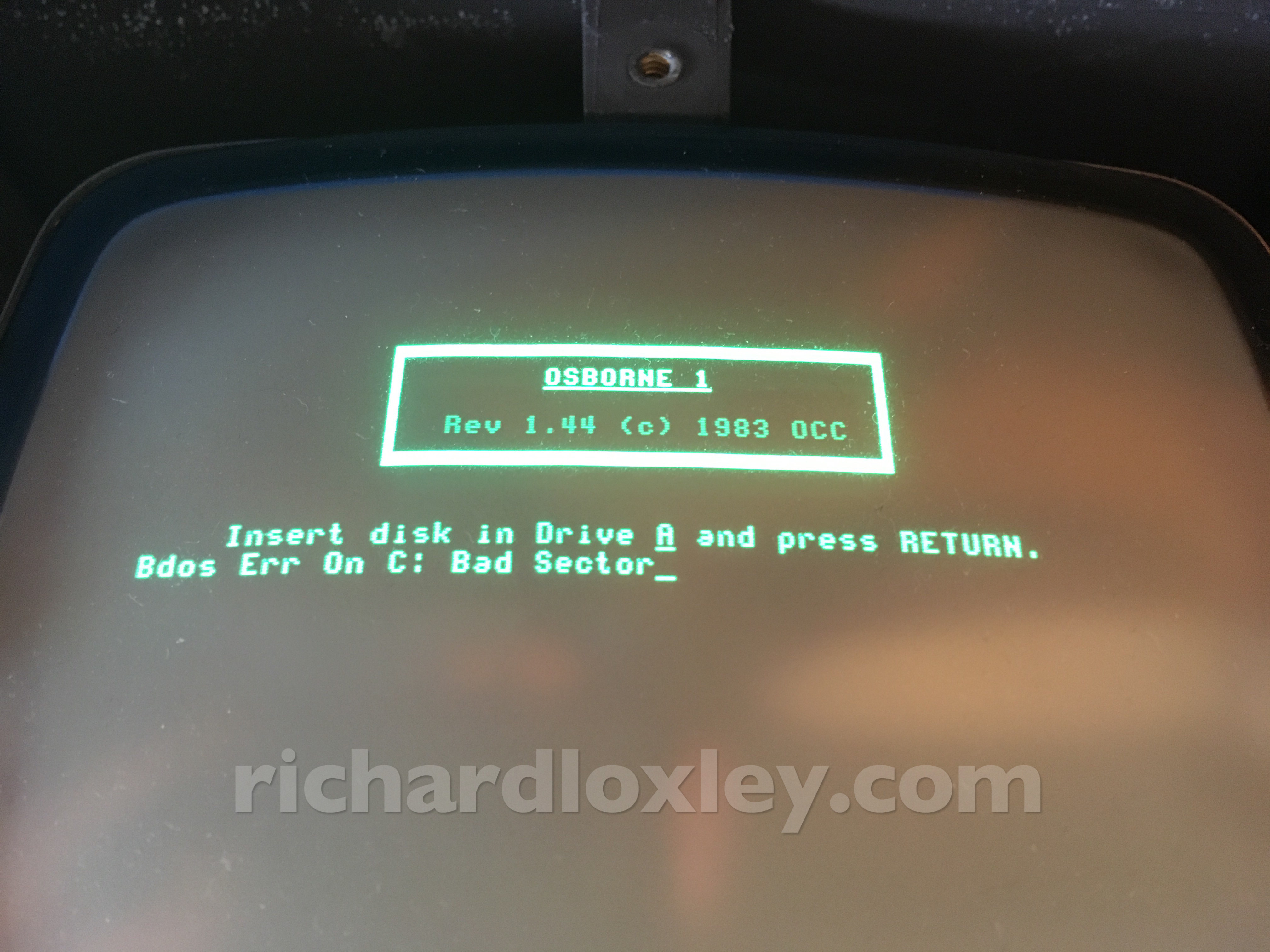
Well at least it’s trying now. Strange that the error refers to drive C: when the Osborne only has A: and B: though.
I then tried removing J3 and the DD board, putting jumpers on J4 and J5, and trying to boot from an SD image. That still didn’t work. But it didn’t give the Bad Sector error, it just tried to read the disk and then stopped, with no message. Strange.
Next let’s try replacing the MB8877 floppy controller chip with the ‘new’ one (date code 1987!)
Sadly, the same behaviour as the old chip (“Bdos Err On C: Bad Sector”). So it looks like the chip isn’t the problem (unless I’ve got two with identical faults).
So that’s where I left it for day one…
Day two, and I’d had a good think about the problems.
Assuming I hadn’t made any mistakes in my diagnostics, it looked likely that the problem was somewhere on the main logic board of the bad Osborne.
Today I would confirm that by swapping out components with the good Osborne.
I also had a look through the Osborne technical documentation. I found the Preliminary Service Checks which I should definitely work through.
I also found the full schematics in the Osborne 1 Technical Manual (1982). The disk controller schematic was on page 124:
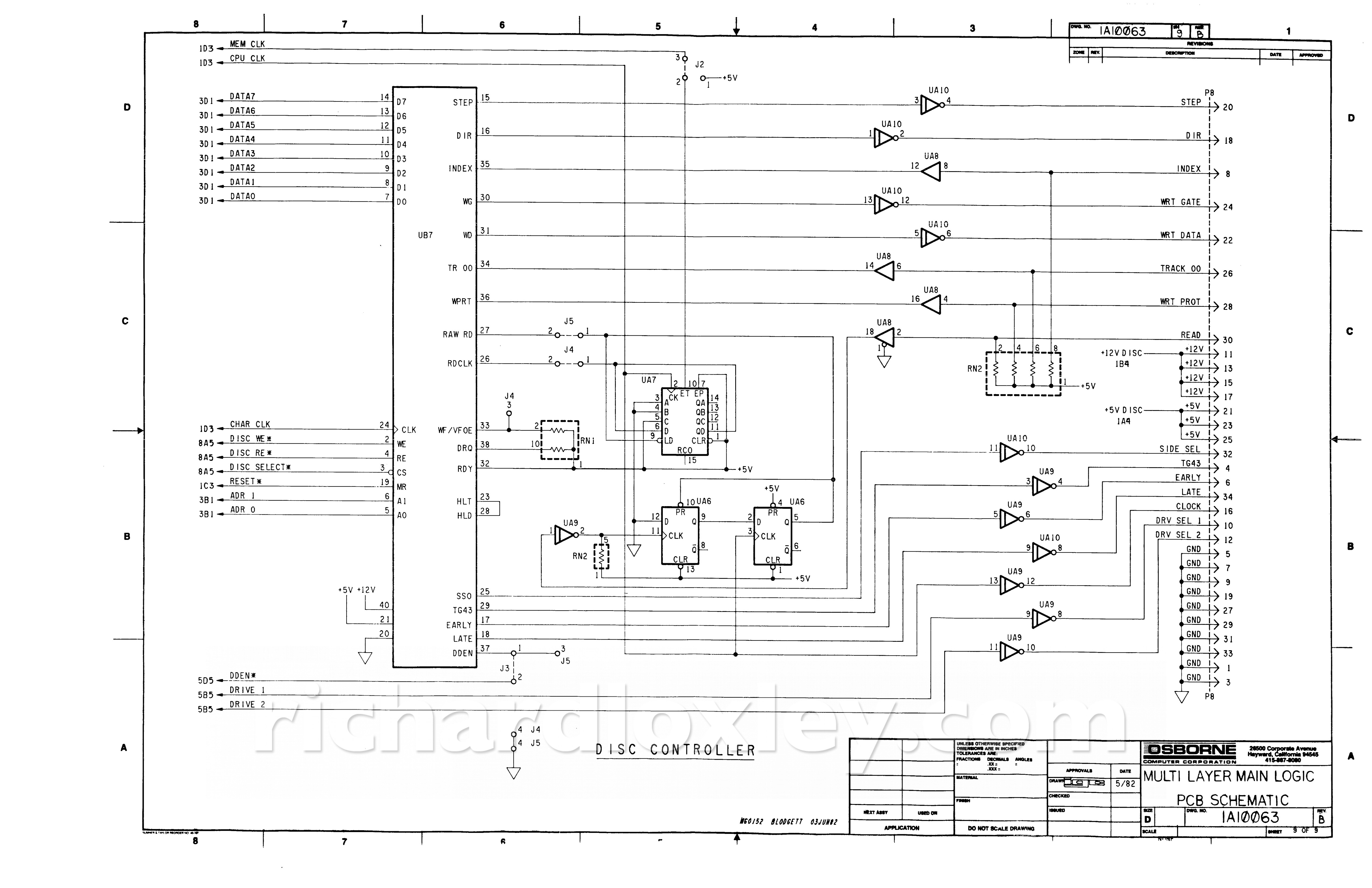
Apart from the controller chip itself, just a handful of ‘glue’ logic: some logic gates, flip-flops and a 4-bit counter. That should be feasible to debug – but probably quite hard without an oscilloscope.
So, to work. First off the preliminary checks.
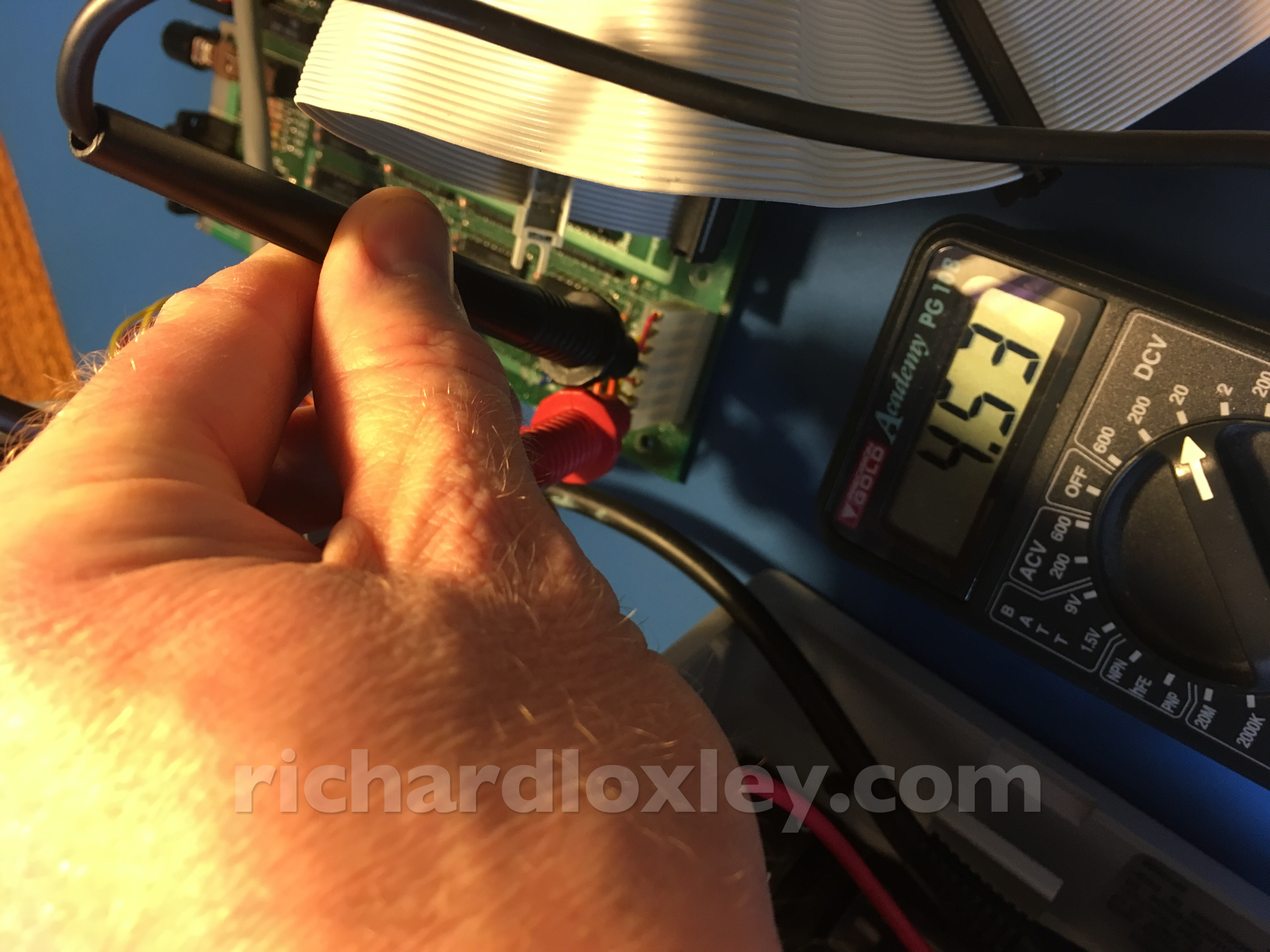
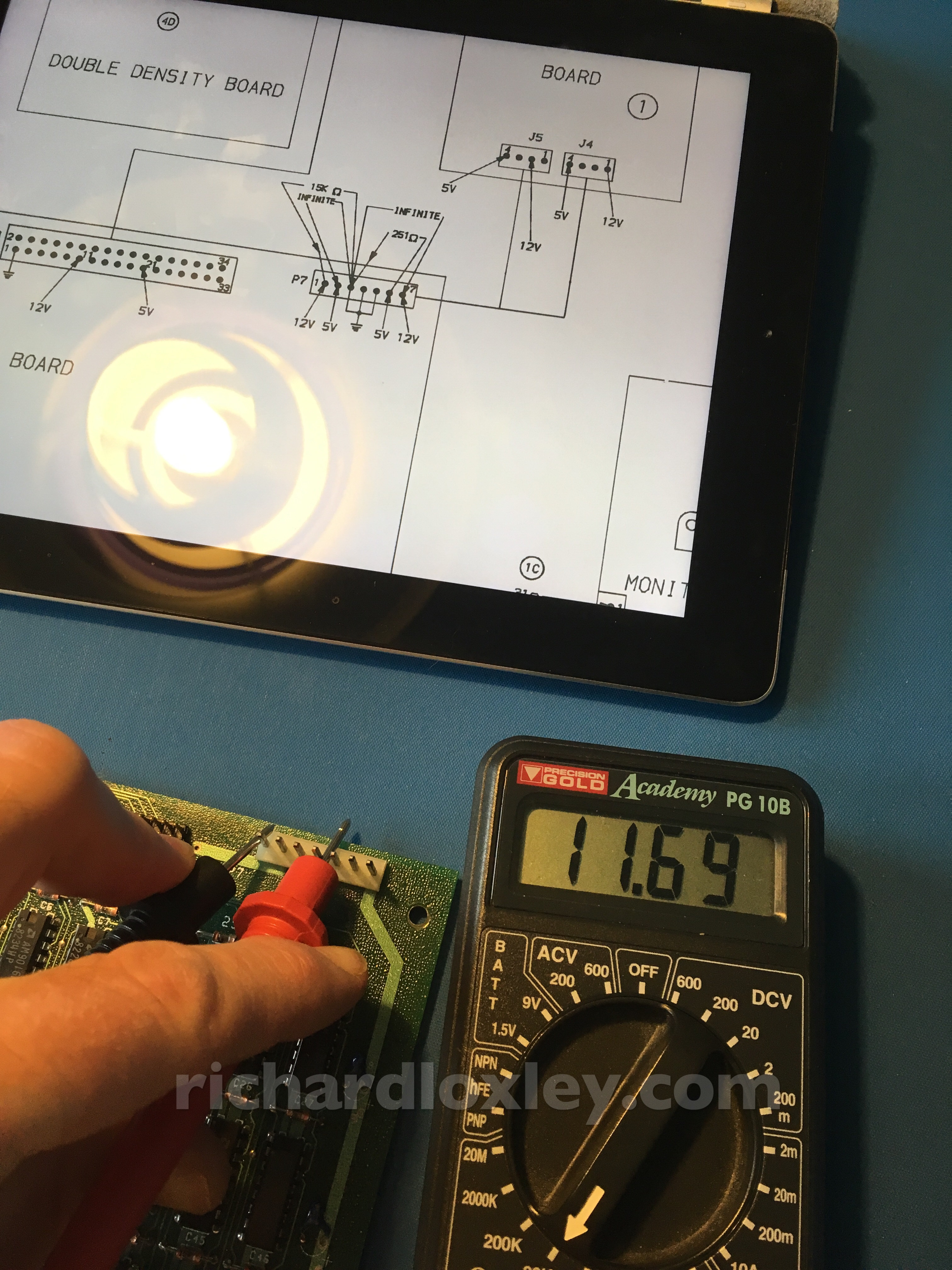
Power supply gives 11.84V (nominally 12V). Looks ok.
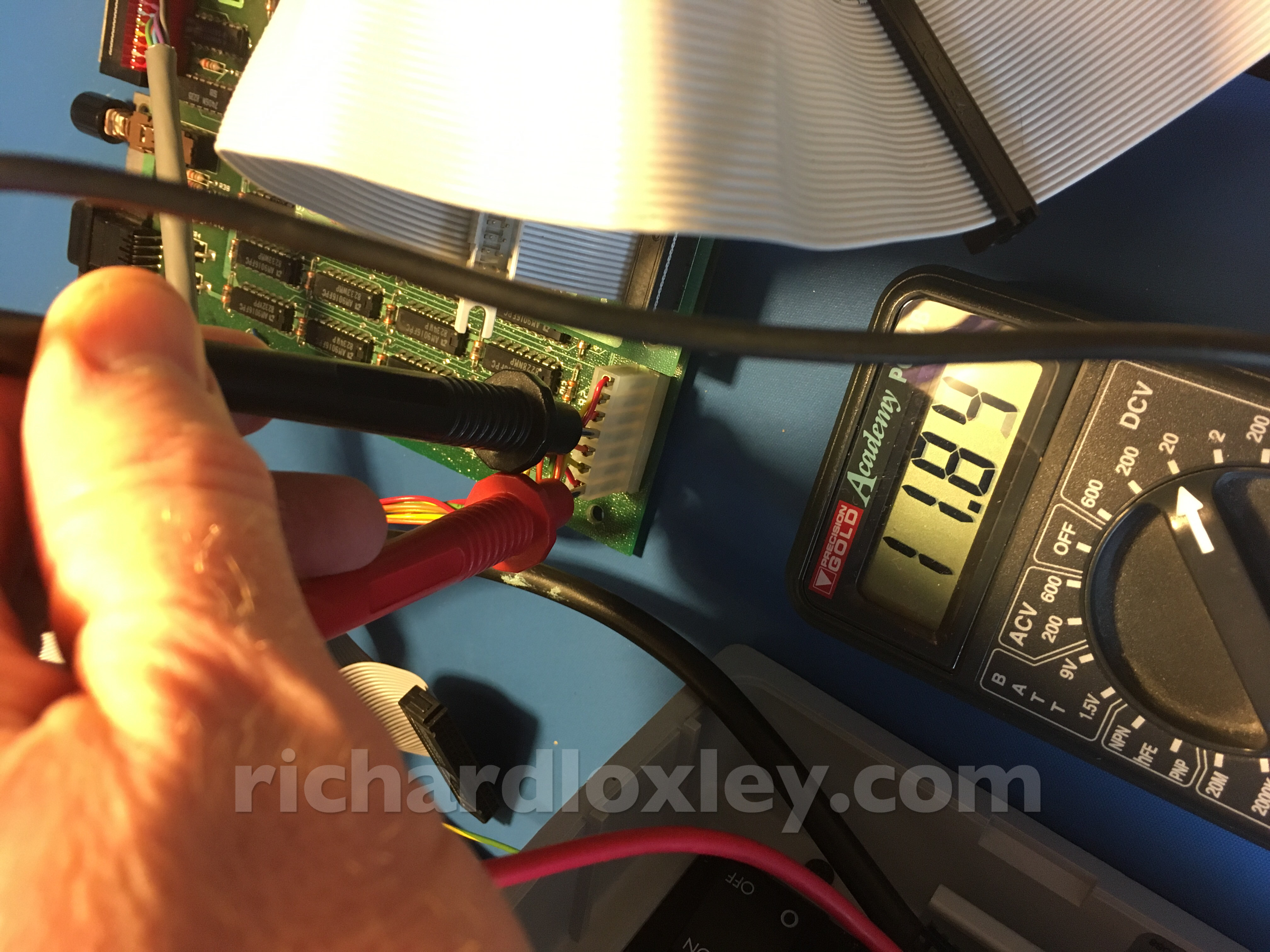
The 5V rail shows a maximum of about 4.5V (and fluctuates down to 4.2V). Could that be a problem? I’ll check later when we swap components between machines.
Then I work through the expected resistances between pins on the logic board and double-density board.
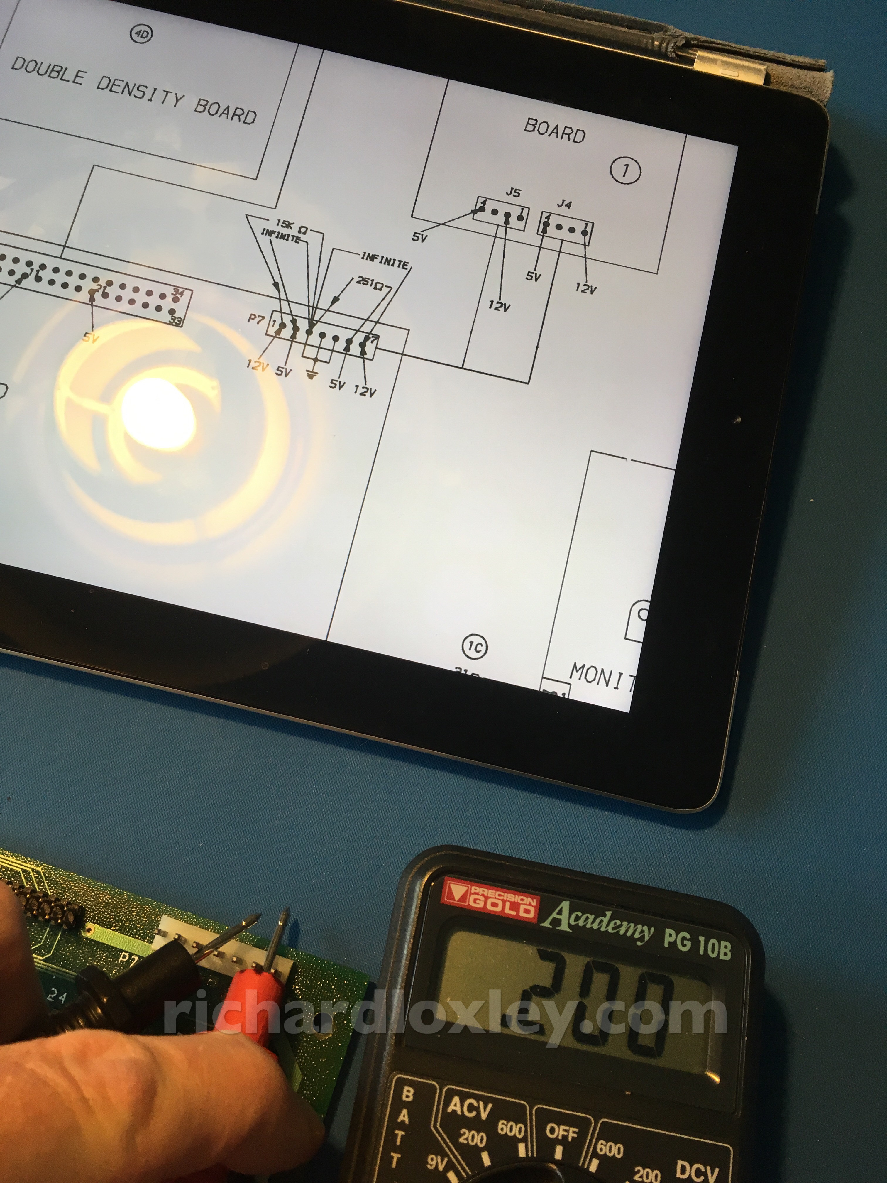
All check out ok.
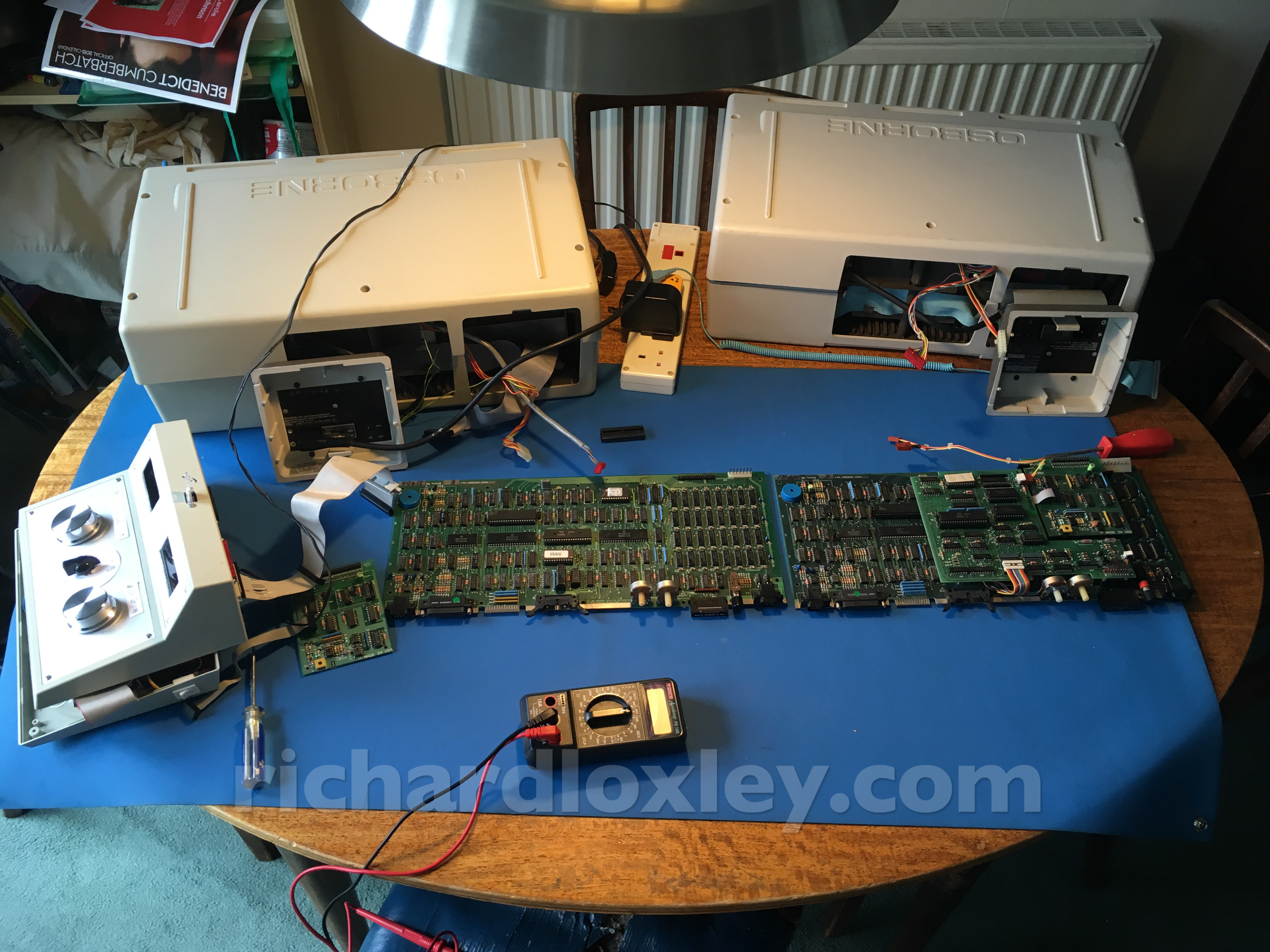
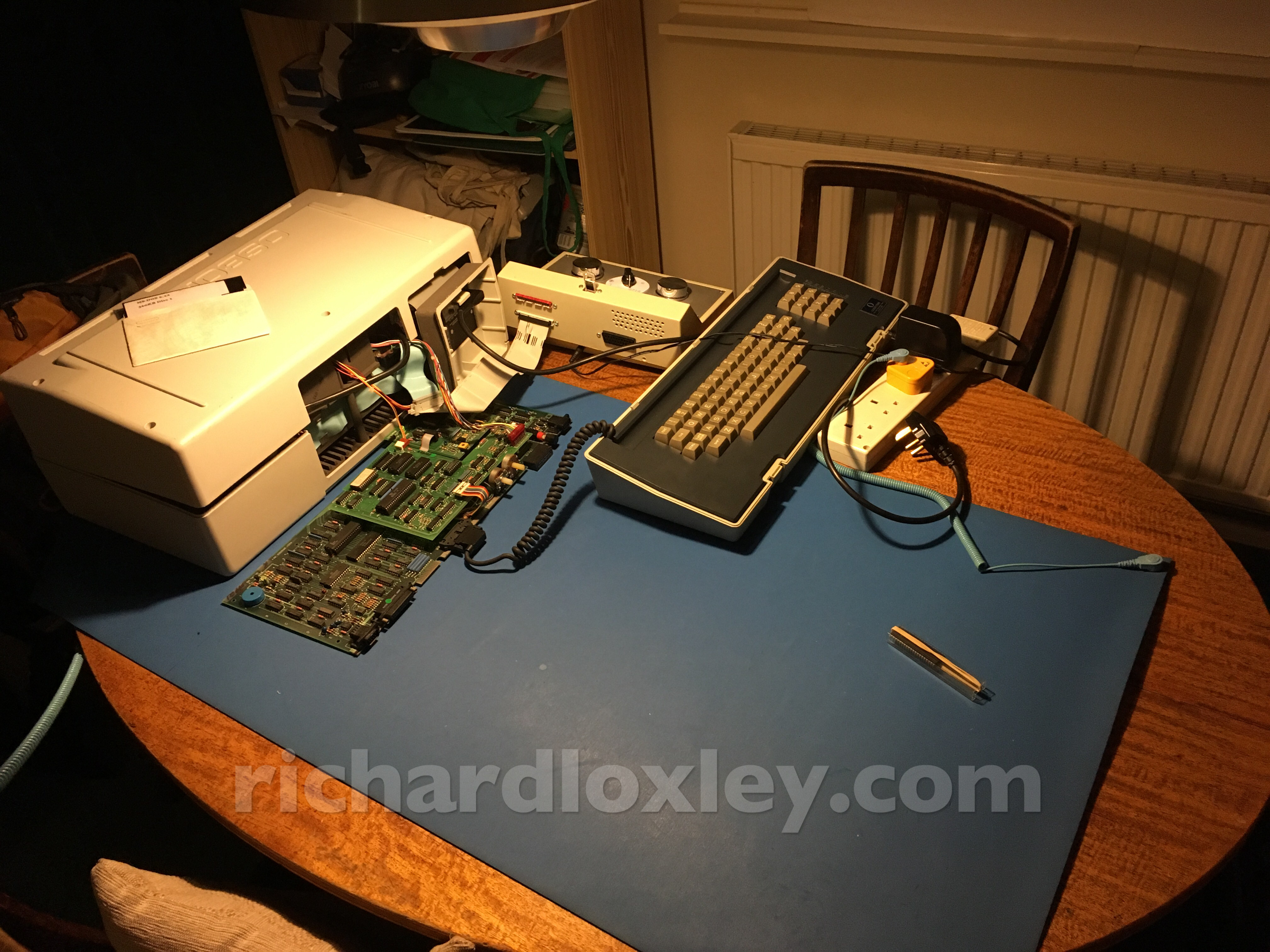
Next to try swapping components between the two machines. This will take some rearranging of the dining table which doubles as my workbench to fit everything in!
All set:
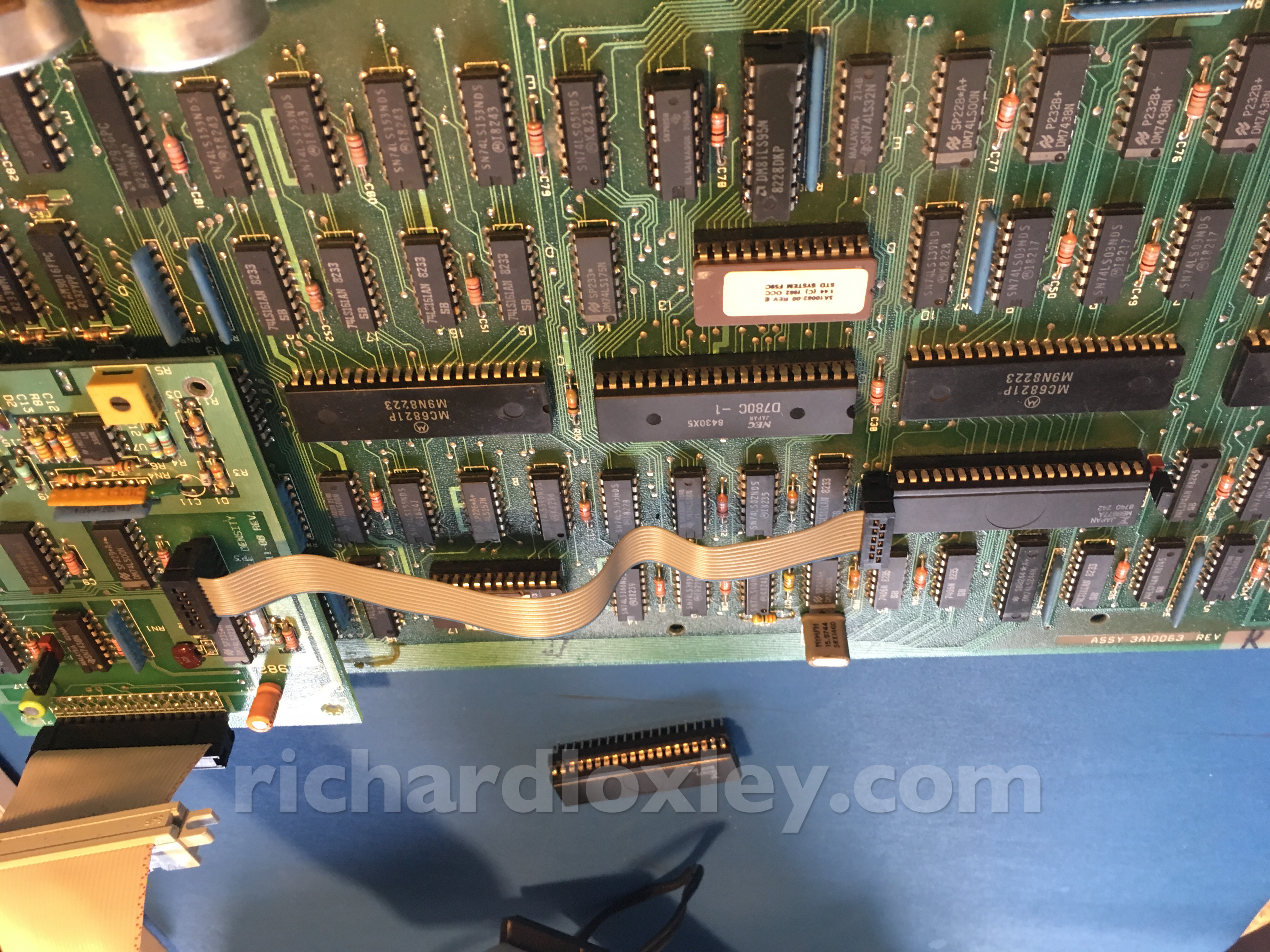
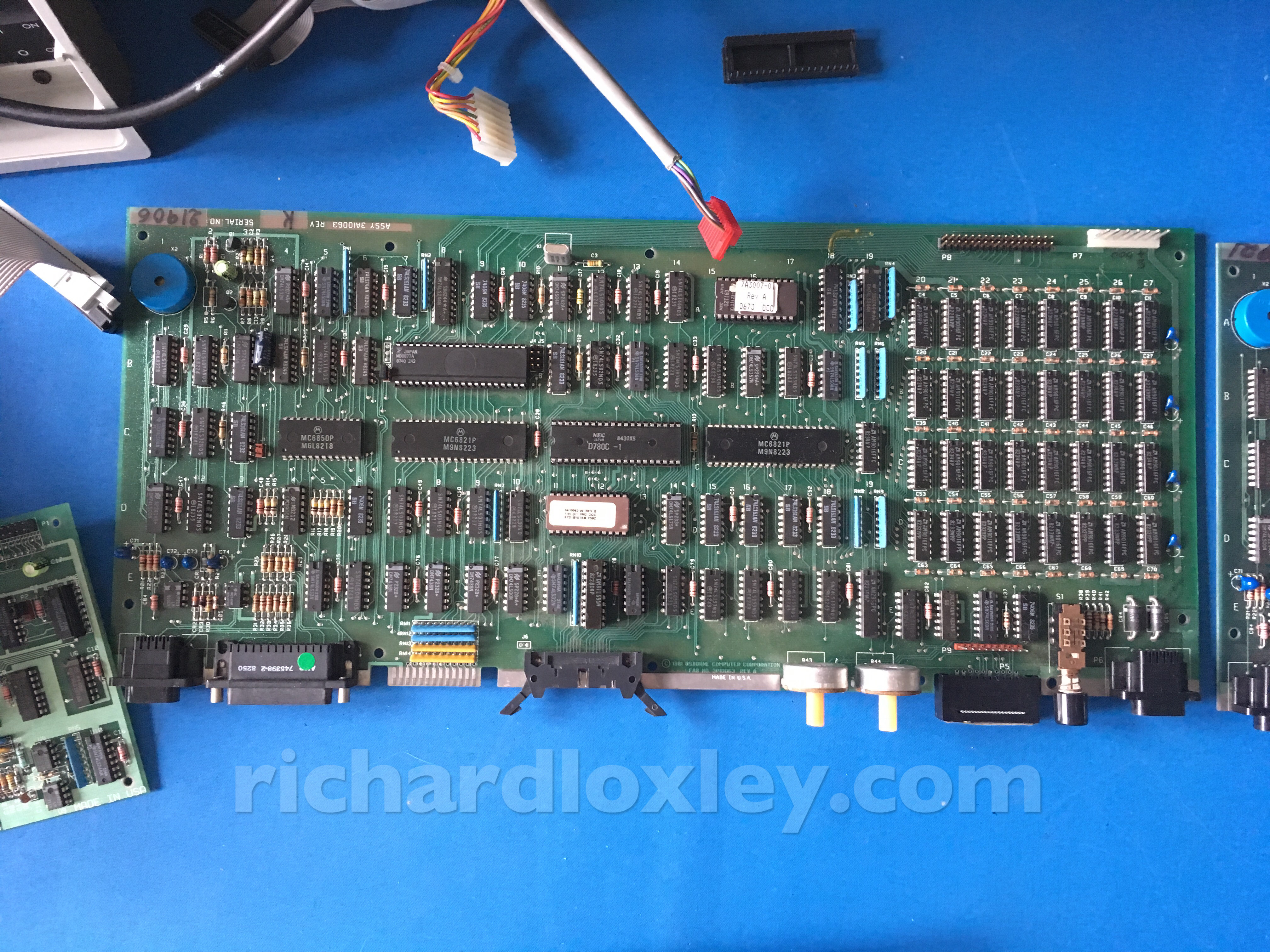
While I’ve got them out, I’ll take some decent photos I can refer back to of each logic board.
The bad Osborne (with DD board removed):
The good Osborne (DD board and Screen-Pac board still installed):
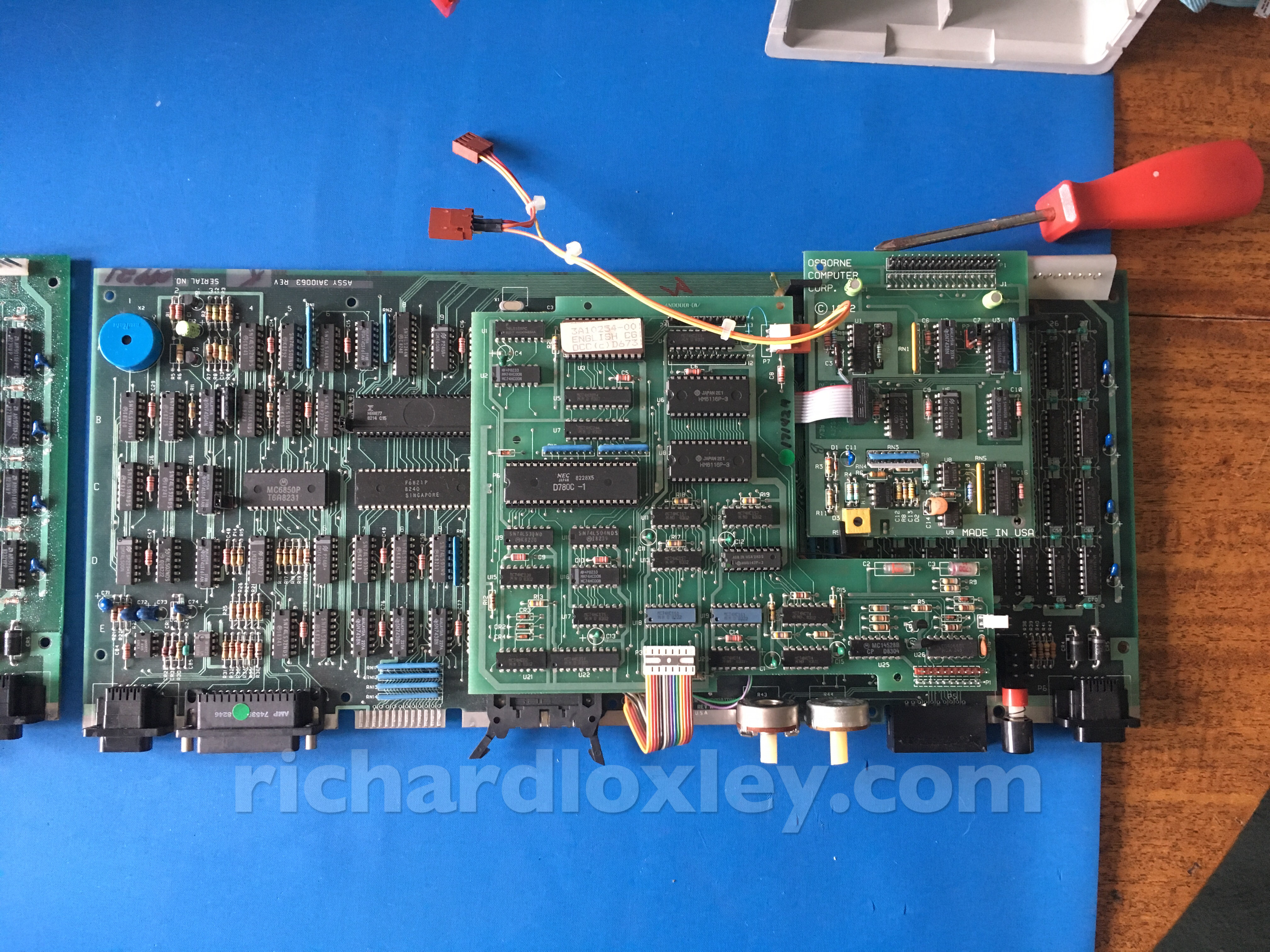
Sadly it seems I can’t easily remove the DD and Screen-Pac boards from the good Osborne. The DD board is fixed in place with plastic stand-offs which are glued to the main logic board. I don’t really want to break the glue and then reattach it.
And the Screen-Pac (80 column graphics card) mod is not easily reversible. It seems the Z80 processor and the character-generator ROM are moved from the main logic board to the Screen-Pac board and then the Screen-Pac board is plugged into the two empty sockets:
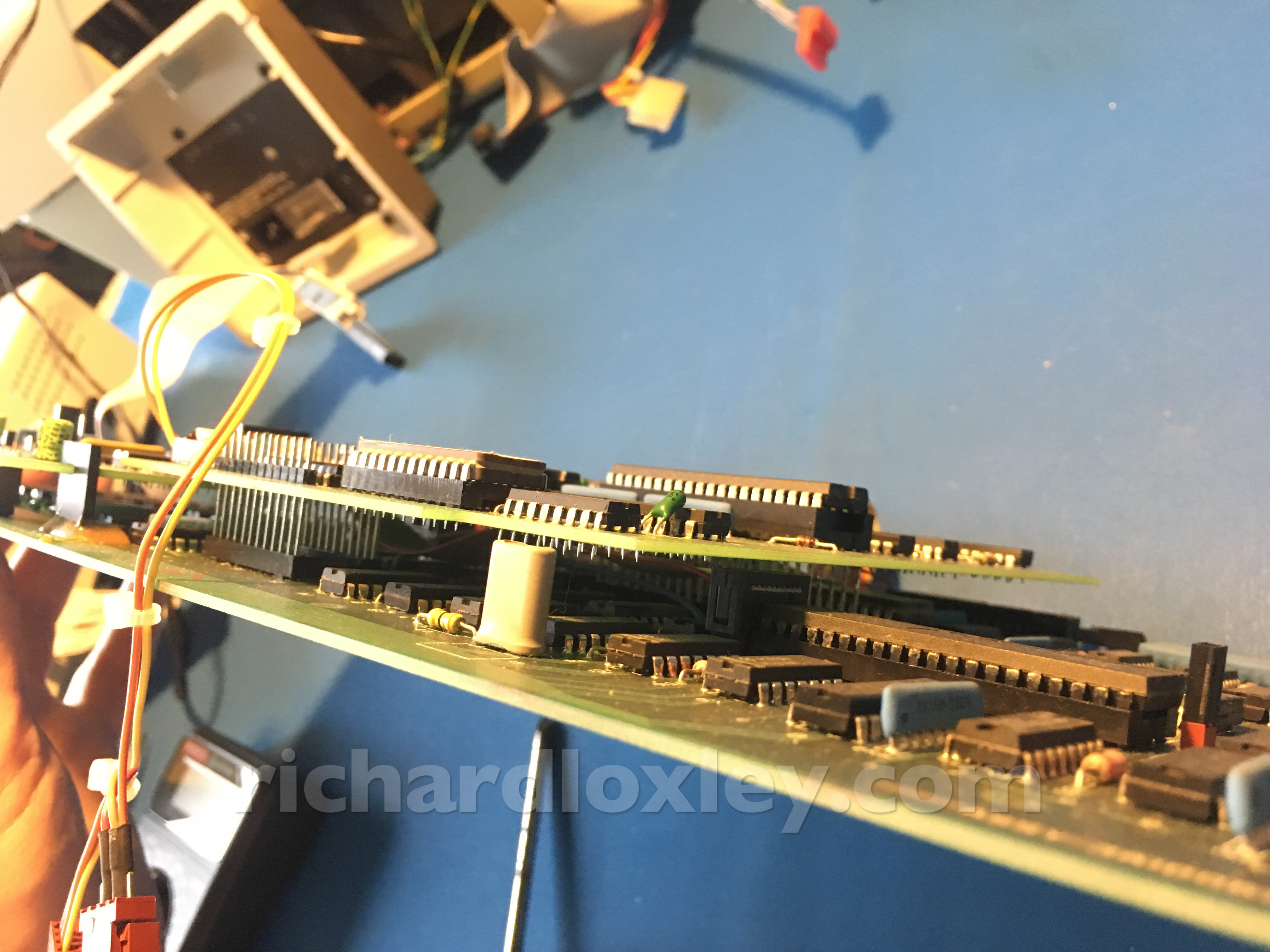
Worse, it has a network of wires soldered directly on to pins of various ICs on the main board!

Yup, that’s not going anywhere. It also covers the ROM containing the CPM boot loader, and partially covers the MB8877 floppy controller, so I can’t easily swap those out in my tests.
So about the only test I could do was swapping the logic boards (with the attached daughter boards) between the two chassis.
But that in itself was revealing. When the logic board from the bad Osborne was attached to the good Osborne, it fails to boot with exactly the same symptoms. So the fault is somewhere on that board (or the corresponding DD board).
I then put the good logic board in the bad Osborne. It worked perfectly, and I could boot up on either A or B drive. So at least that means everything else is fully working – the PSU is fine, the monitor works (although I knew that already), and both drives work and are correctly calibrated.
So that’s fairly good news. If I can fix the logic board, I’ll have another good Osborne.
So my current theories of what the problem might be:
- Some of the ‘glue’ logic around the floppy controller chip may be faulty, giving bad data from the drives.
- Some of the RAM (or the RAM support logic) may be faulty (the bootloader will presumably buffer the relevant sector off the disk into RAM)
Or maybe something else I haven’t thought of?
I could diagnose these theories further if I had an oscilloscope. I’m saving up for one, but don’t have one yet.
Another idea is I could write some Z80 assembler and burn it to an EEPROM to replace the bootloader. I could test the memory, and possibly even test the disk controller. But that’s quite a job (and I don’t have an EEPROM burner yet).
It’s annoying that the Osborne 1 originally had hardware diagnostics built into the ROM, and the instructions still say you can run them by pressing Control-D instead of Return when you turn it on. But that doesn’t work, and apparently only ROMs prior to version 1.3 have that, as subsequent revisions deleted them as they needed the space for other routines. The diagnostics are now loaded from a disk (which is no use for me diagnosing disk problems!)
I haven’t yet found a copy of an earlier ROM online. If I did, that might give another diagnostic tool.
Anyway, I don’t currently have the correct tools to diagnose the bad Osborne’s logic board any further. So I’ve reassembled it, and stored it away for another time (next year’s Retro Challenge maybe?)
And I’ve rearranged the good Osborne (while still in pieces) so I can start trying to copy USB disk images to physical disks to bolster my software library:
But that’s for another day.