This is part of a series of posts for the Retro Challenge 2018/04. See my index page for the other posts.
My next stage with my Osborne computer was to bulk transfer CPM software I’ve downloaded from the internet onto the computer.
In last year’s Retro Challenge I made my RetroMatic 2000, which included a USB floppy drive emulator based on Gotek hardware with HxC firmware.
I’d already tested that this worked with the Osborne with a custom cable, so my plan was to open up the Osborne, connect the cable, copy all the software to real floppy disks, then reassemble the computer.
Little did I know that this simple job would turn into a 3+ day marathon…
Day 1.
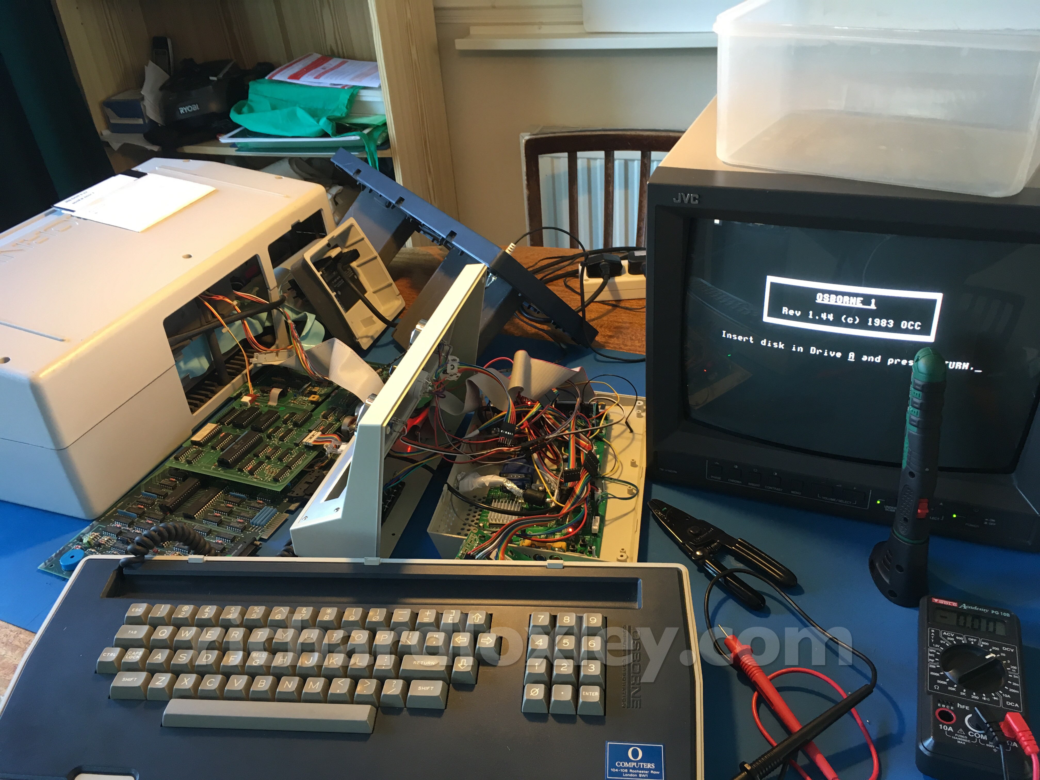
I connect up the Osborne to my custom floppy cable, with the Gotek/HxC drive alongside one of the physical drives. I also connect an external monitor since the internal monitor will be facing away from me and upside down!
I can access the Gotek/HxC drive, but when I try to access the physical drive the Gotek/HxC drive also tries to respond, and so neither work.
Many hours of debugging ensues, including dismantling and reassembling a faulty drive-selector switch on the RetroMatic 2000, and resoldering connections that have become detached. But eventually I trace the fault to a jumper I installed that forces the Gotek/HxC drive to respond to any drive signals, because I previously discovered the drive select signals weren’t getting through correctly. Doh! I’d forgotten that jumper was still there.
I remove that jumper and try again. But now the problem is worse. The Gotek/HxC drive won’t respond to any signals (although the physical drive now works correctly).
I had presumed that the faulty drive select signals I’d seen before were connected to the faulty floppy interface on the bad Osborne motherboard. But the problem is still there with the good motherboard. It seems I was wrong :-(
The Gotek/HxC drive still works with the Amstrad CPC 464 and 6128 machines. It had previously worked with a Video Genie too. What was different about the Osborne?
I’d wasted a whole day so far on this. Time for sleep and then a fresh pair of eyes tomorrow…
Day 2.
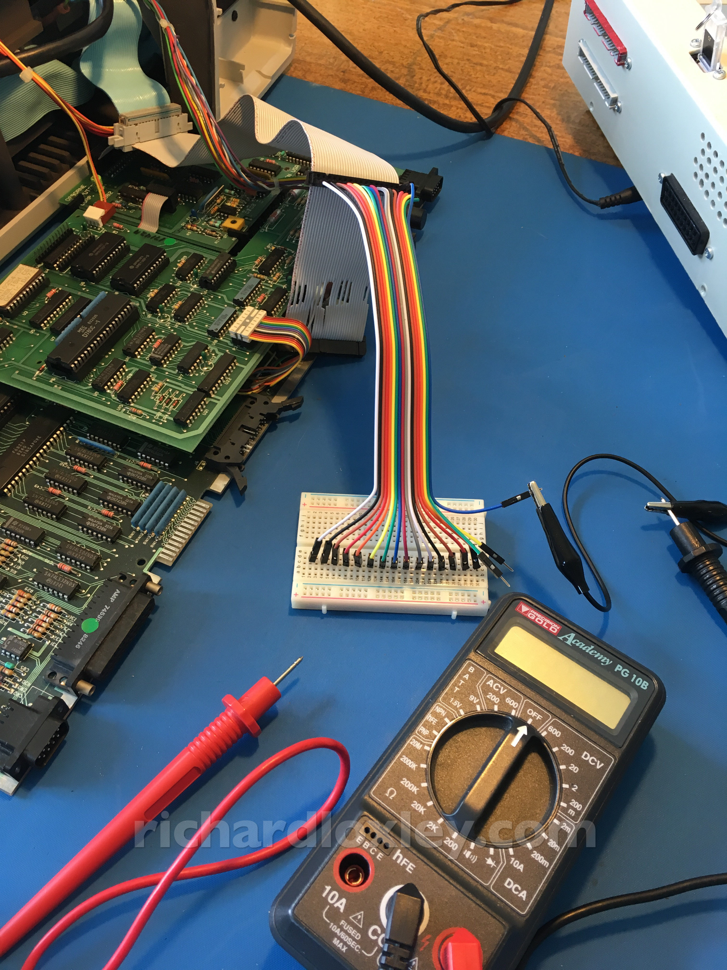
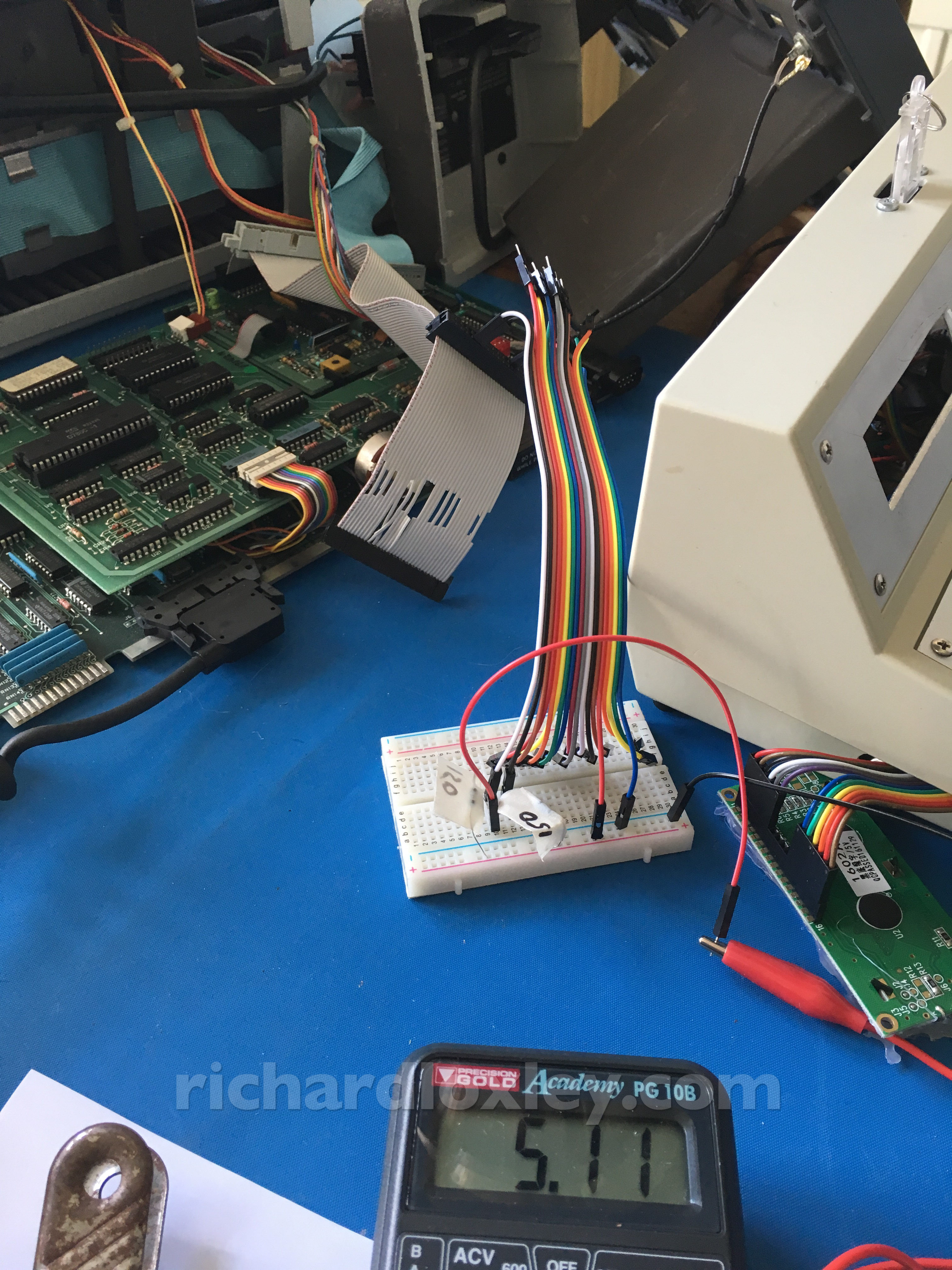
I break-out all the signal connections from the floppy cable to a breadboard (via a spare floppy connector) for further analysis. I could then connect up my multimeter to see what was going on:
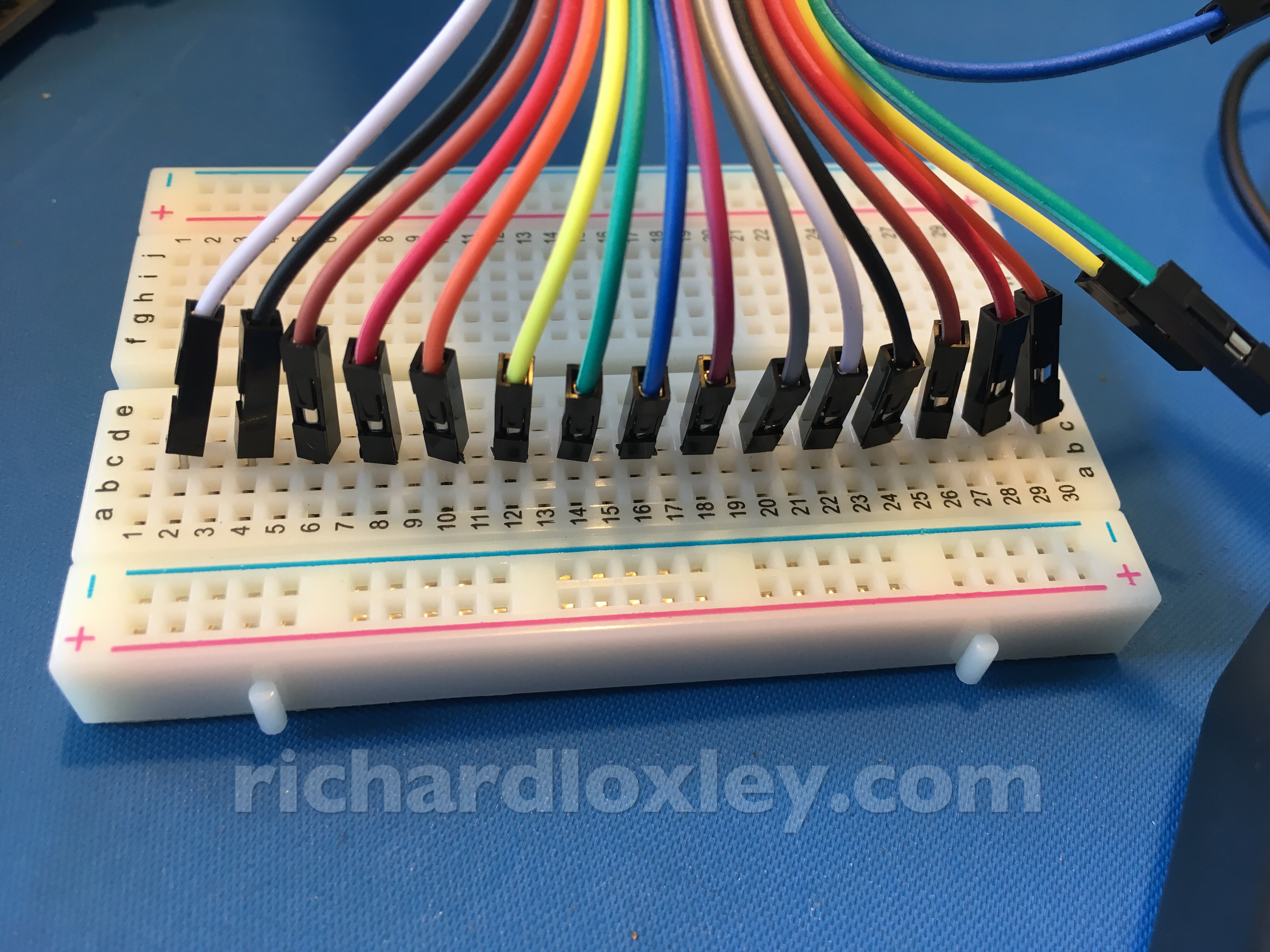
I spread out the connections so the numbering on the breadboard matches the floppy pin-out numbers for clarity (all the signal pins are on the even-numbered side of the connector):
My initial thought was the pull-up resistors on all the signal lines. The Shugart floppy standard has all lines pulled-up to 5 volts (via pull-up resistors) at the receiving end. Then the sending end will pull them down to ground (0 volts) to indicate a data signal.
Modern equipment (including the Gotek hardware that the HxC firmware runs on) uses 1K ohm pull-up resistors. Older equipment tends to use 150 ohm pull-up resistors. In the Osborne, the A drive contains 150 ohm resistors, and the B drive has nothing. (I also double-checked all these values matched reality using the resistance setting on my multimeter):
This means if the Gotek/HxC is connected alongside the A drive, there are both 150 and 1K pull-up resistors connected simultaneously. If the Gotek/HxC is connected alongside the B drive, there will be just 1K resistors (which might be incorrect for the B drive?)
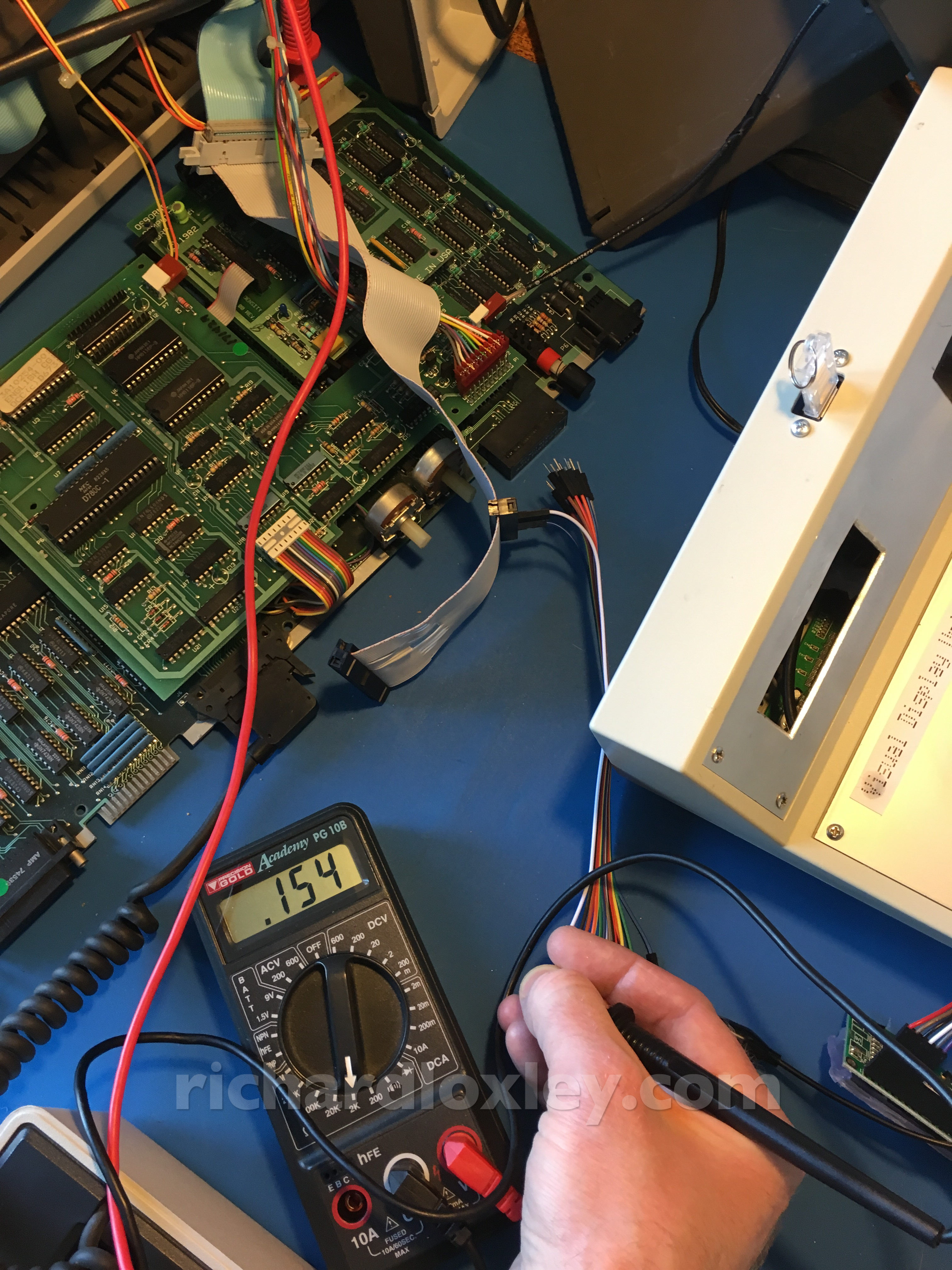
So I try connecting just the motherboard to the floppy cable, and add my own pull-up resistors to the breadboard, and get the computer to try and boot from each drive. That way I can compare the effect of different resistors, and whether the motherboard can drive those signals:
The results were as follows:
Nothing connected to the motherboard: it would set the relevant drive-select line to 0.06V.
150 ohm pull-up resistors: the computer would pull the relevant drive-select line down to 0.42V.
1K pull-up resistors: the computer would pull the relevant drive-select line down to 0.14V.
Gotek/HxC connected (with its 1K pull-up resistors): the computer would pull the relevant drive-select line down to 1.59V. Also, despite the Gotek being driven by 5V, the Gotek only pulled the drive-select line up to 4.24V. Something strange happening here. Presumably the 1.59V is too high for the Gotek to consider it as a digital ‘low’ signal, which is why I’m getting problems.
I also noted that because the Gotek/HxC is only physically connected to one drive-select line at a time, the other line isn’t pulled up to 5V. That would cause a problem if connected as an A drive with the physical B drive also connected (since the B drive doesn’t have pull-up resistors).
To eliminate that as a problem, I manually added a 1K pull-up to the drive B line and tested that configuration again. That did correct the drive-select B line, but made no difference to the Gotek/HxC being able to respond to the drive-select A line.
I also considered relative voltages of the two systems (each had their own power supply). But their ground lines were connected together, and tests with my multimeter confirmed there was no potential difference between the Osborne and Gotek that would account for the signal differences.
So all very strange indeed. Time for a break, and a re-think.
To be continued…
Is the Gotek green LED lit when you try to access the drive ?
I don’t remember I’m afraid as that’s hidden inside the case I used. I certainly didn’t get any other signs of activity on the LCD display. Since the drive select line was way above zero volts (about 1.6V) I’m not surprised it wasn’t recognised by the hardware. When grounding the drive select line at the Gotek end to force its selection everything worked fine, so it was just that drive select line that was the problem. I’m still not sure what caused that (fault in this Gotek, or some interaction from my other mods). Hopefully I’ll revisit it at some point.
The 1.6V sound like there is an IC not able to drive correctly the signal to low. There is maybe more than one 150 ohms pull-up on the DS signal. i suppose that you have checked the terminations settings on the floppy drive ?
Also : the 1.6V is maybe a 5V signal toggling. without oscilloscope hard to say…