This is part of a series of posts for the Retro Challenge 2018/04. See my index page for the other posts.
TLDR? Just watch the video demo.
In my previous posts I’d proved a Gotek/FlashFloppy USB floppy drive emulator would work with my Osborne 1. I’d also found a way to install it in a floppy disk storage pocket on the machine.
I then had to wait for more components to arrive, to finish it off in a neat package.
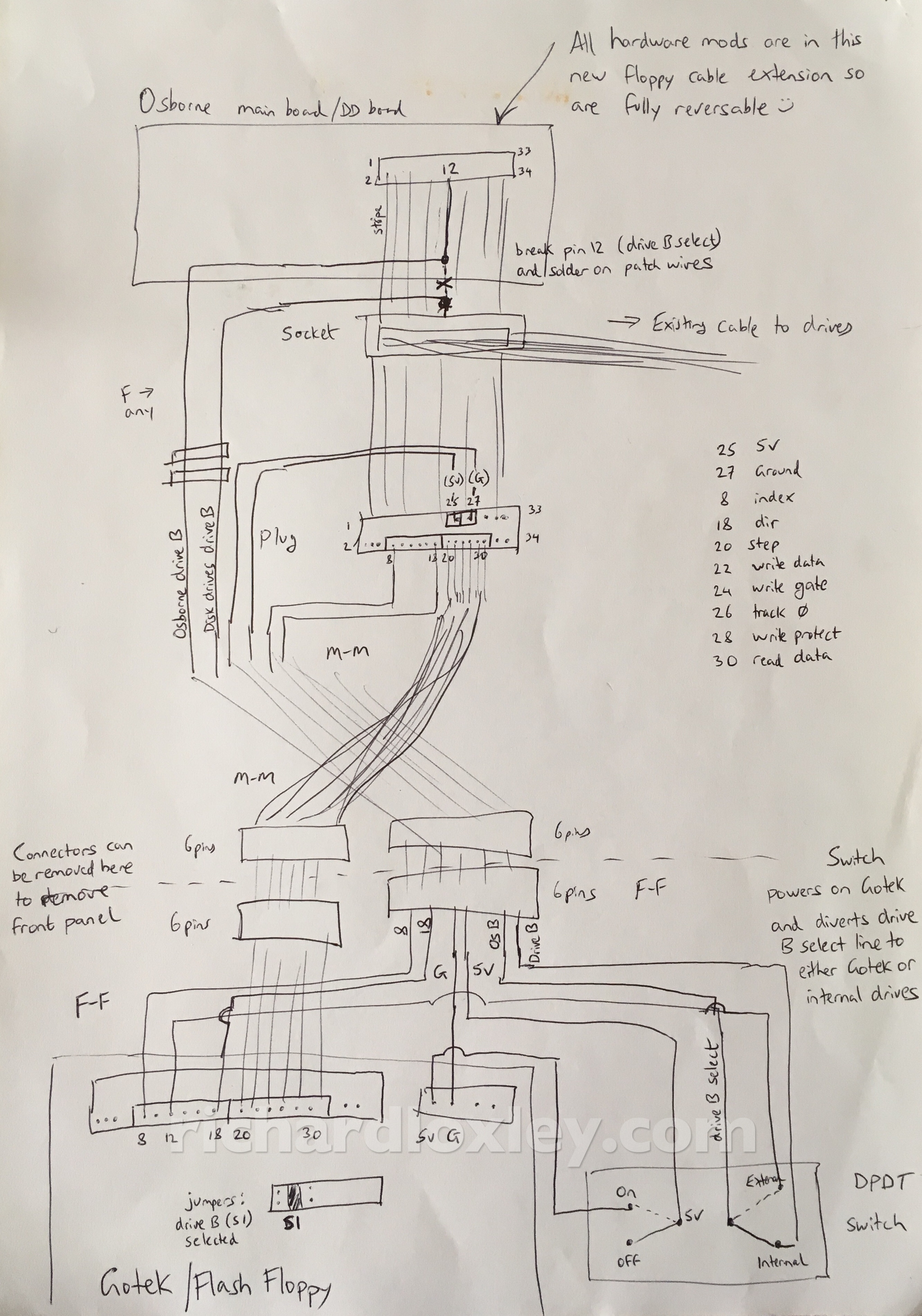
To recap, this was the wiring diagram I was working from. Basically I needed to use a DPDT switch to turn power on and off to the Gotek drive, and divert the drive-select signal line between the Gotek and the physical floppy drive:
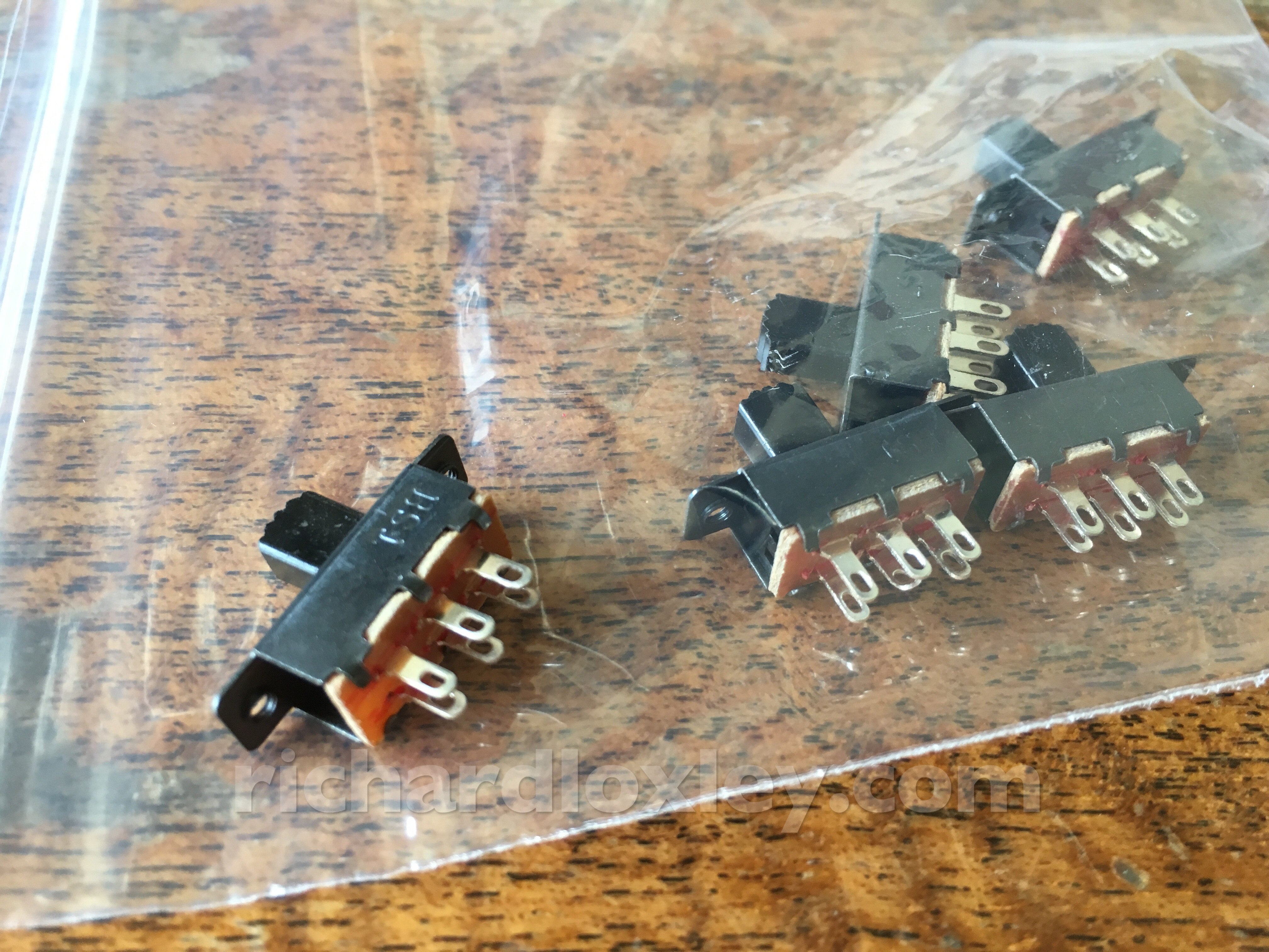
The switches had arrived:
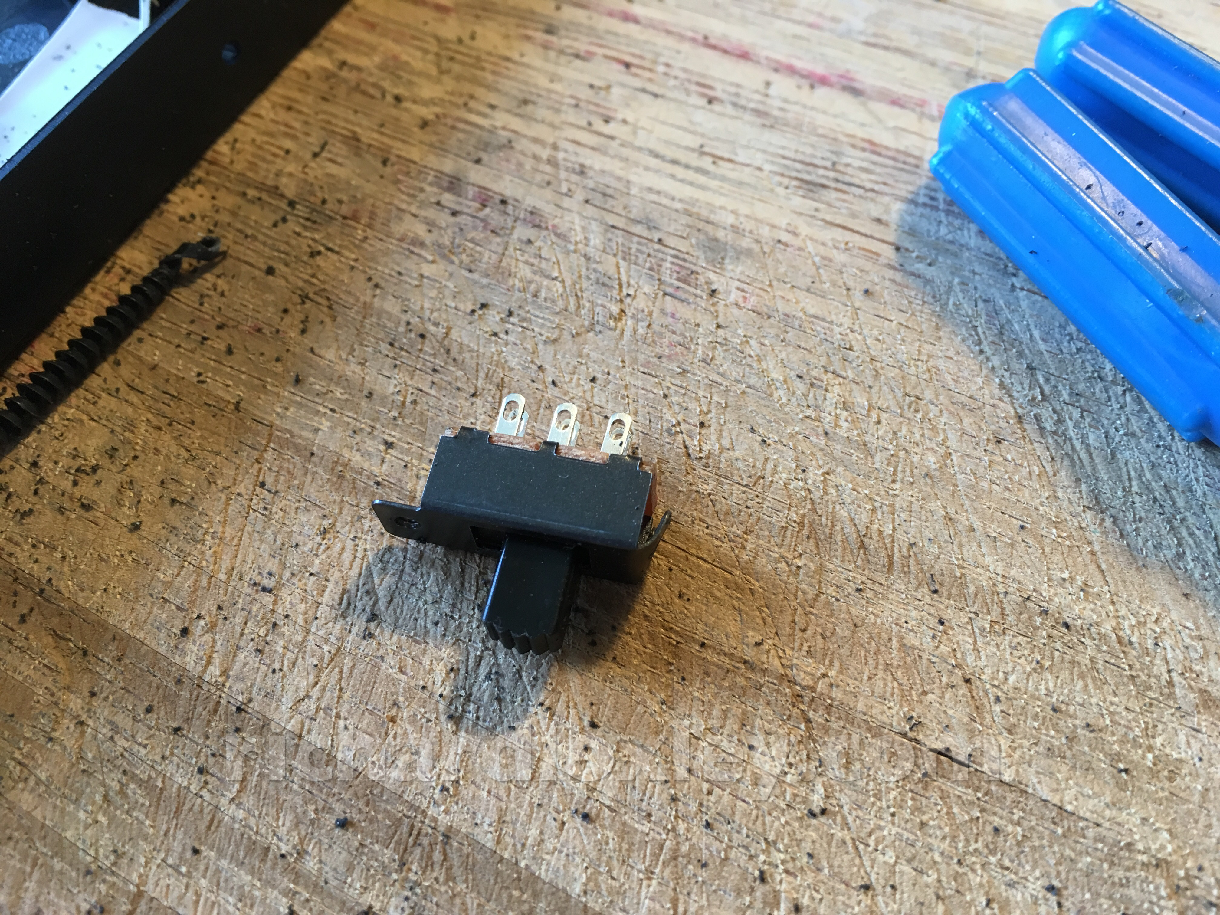
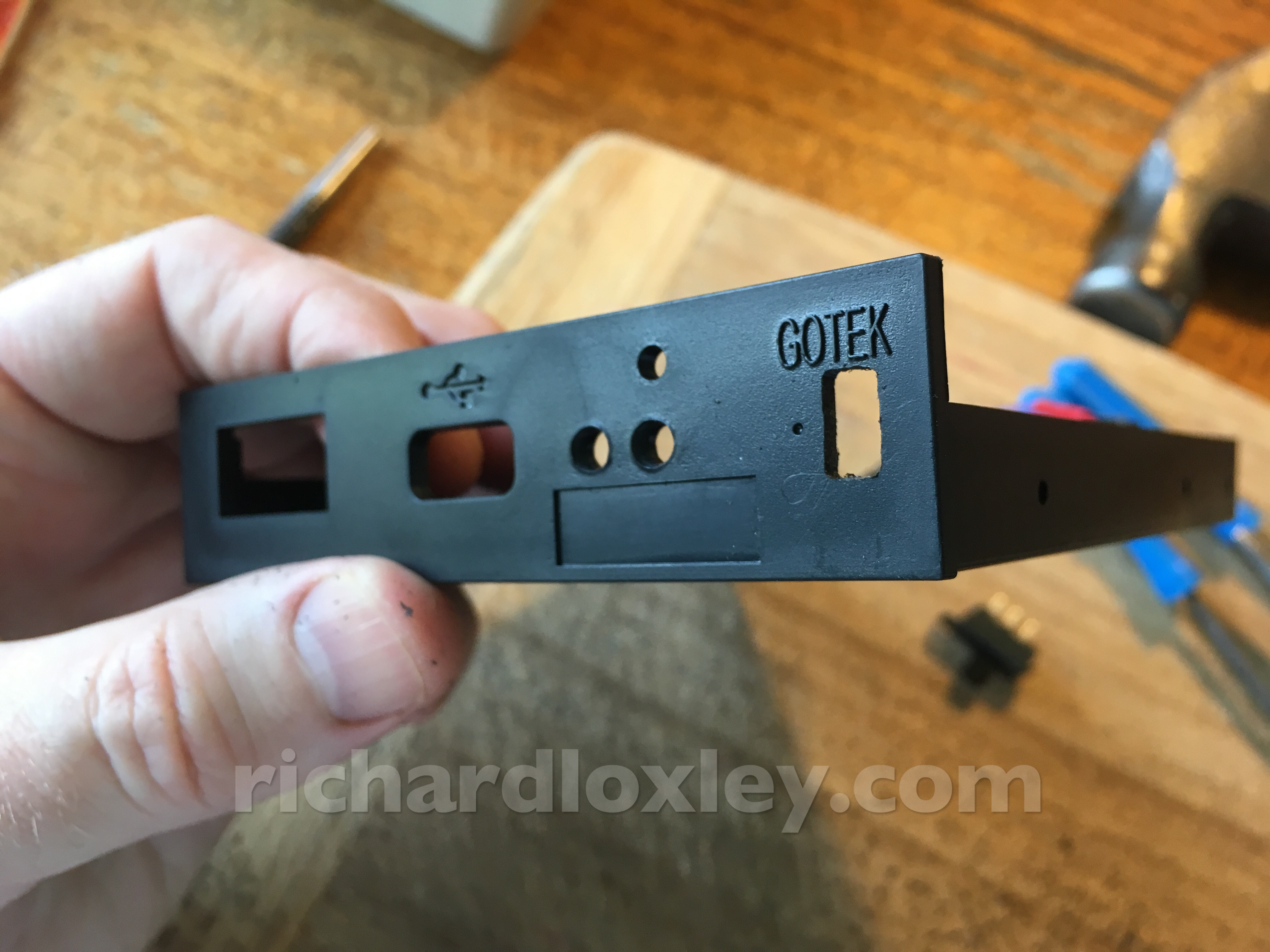
I needed to bend the tab down at one end to reduce its height to fit in the Gotek case:
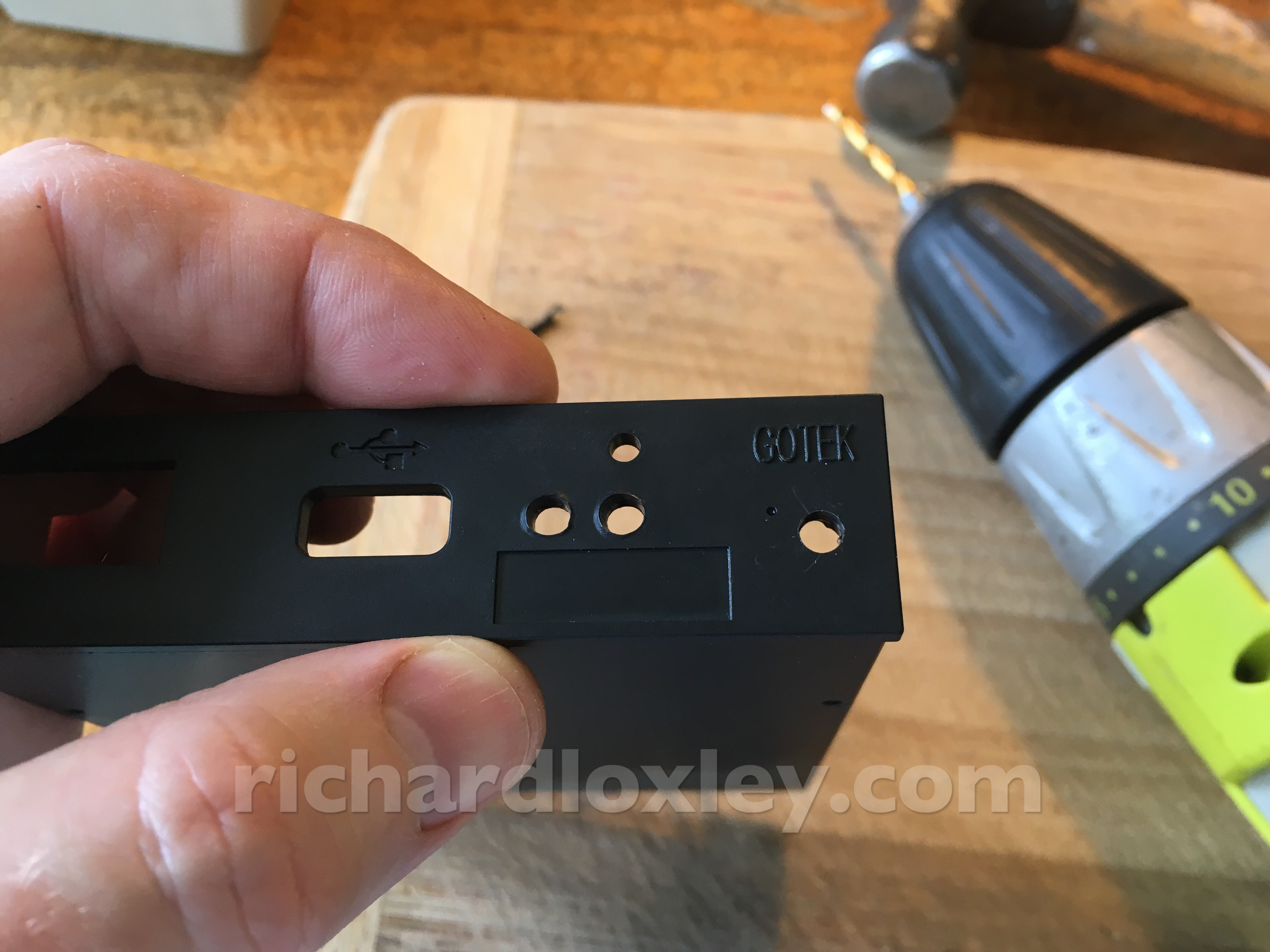
Making a hole in the case for the switch:
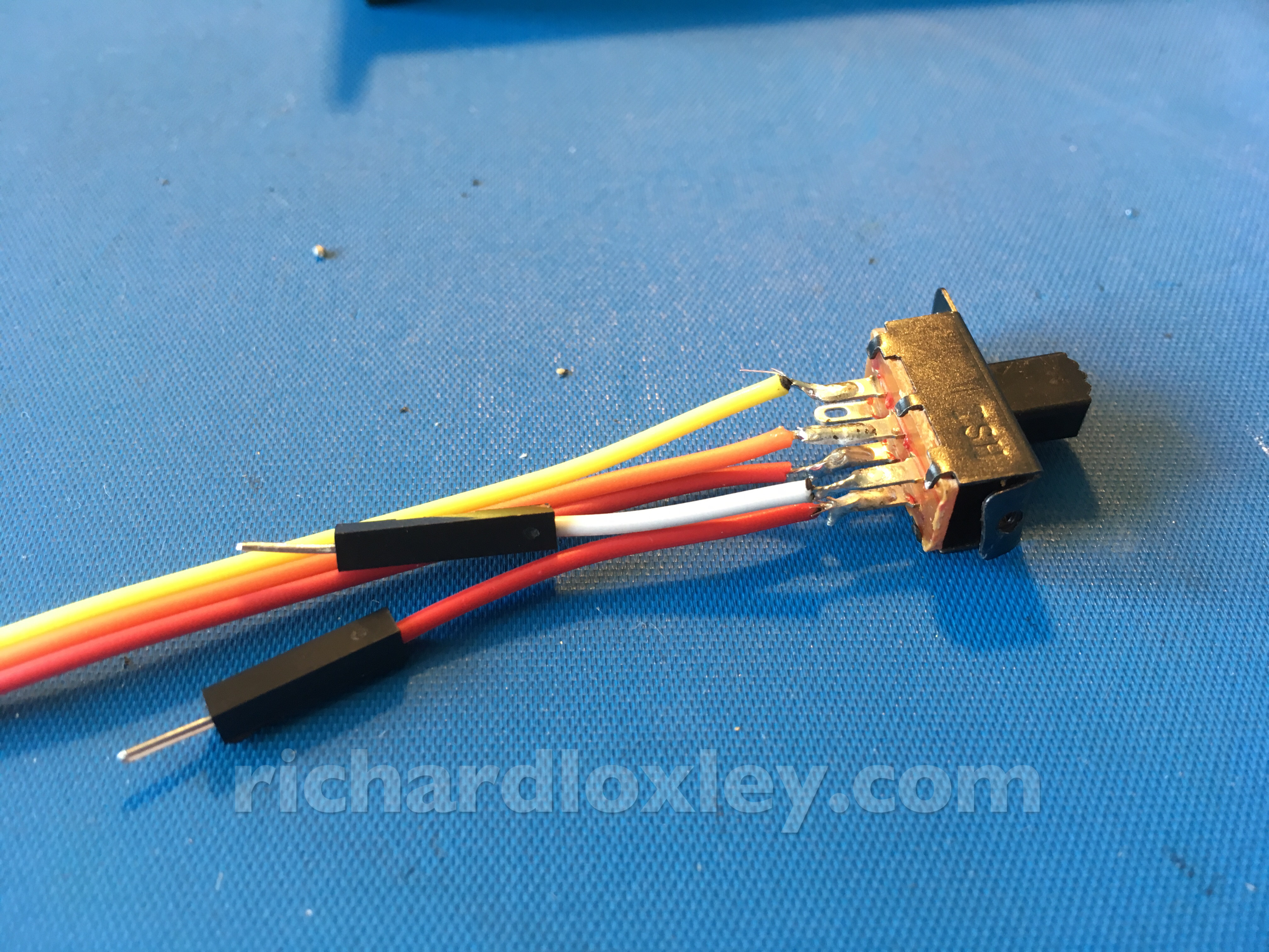
Soldering up the switch:
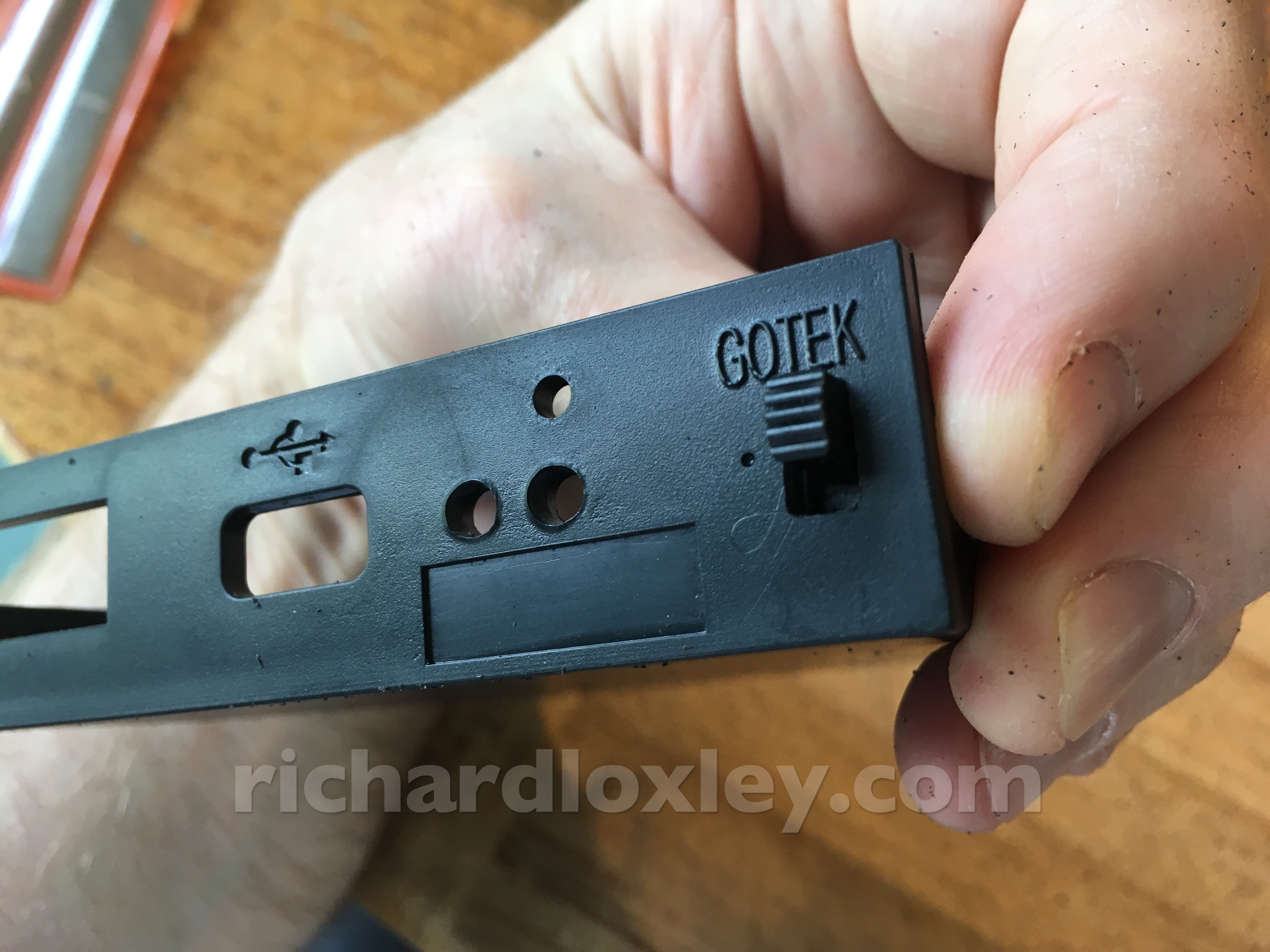
Installing it:
I have a love/hate relationship with hot-glue!
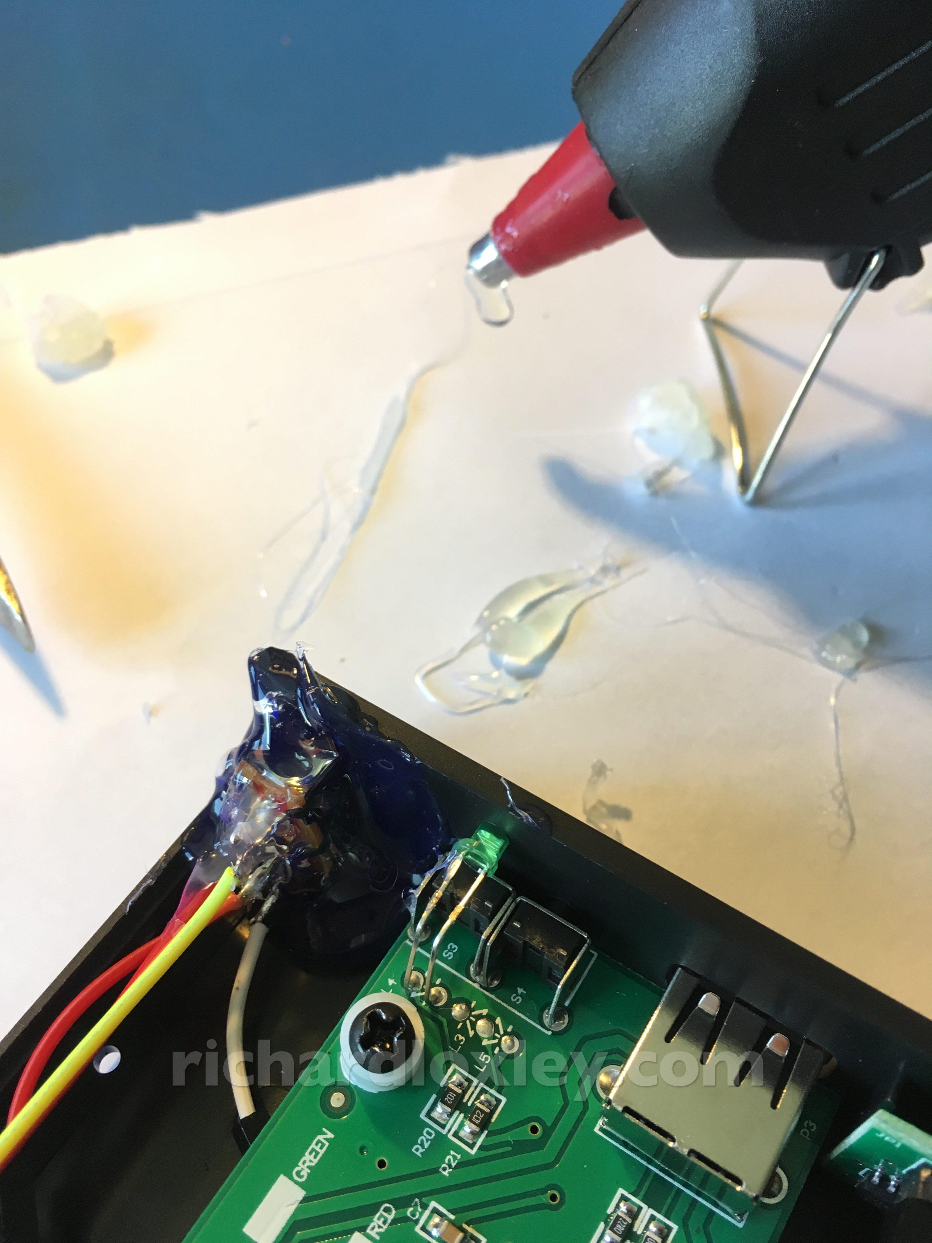
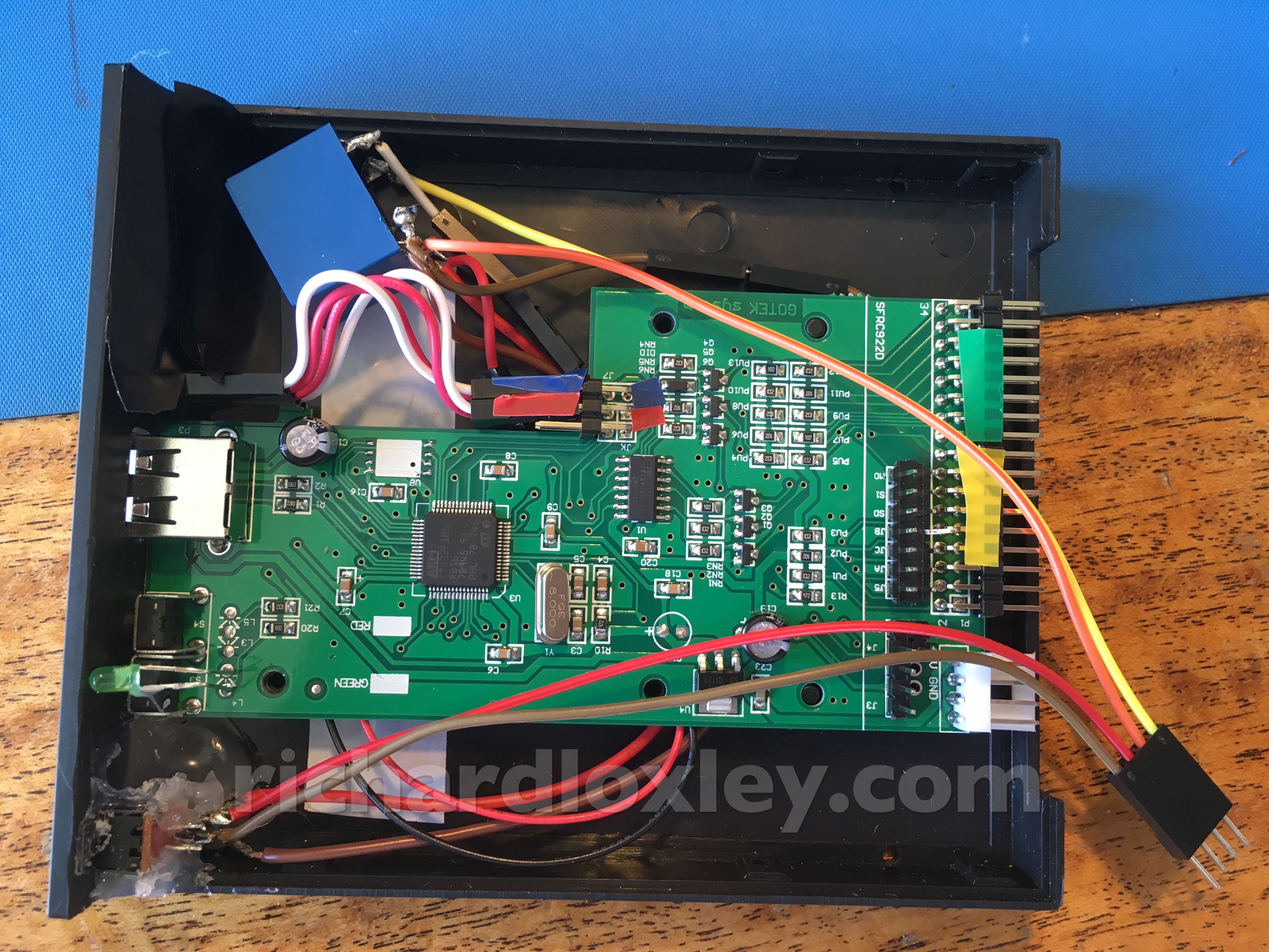
I had to solder wires directly onto the Gotek circuit board, as plugging anything into the headers on the top made it too tall to fit in the hole on the Osborne!
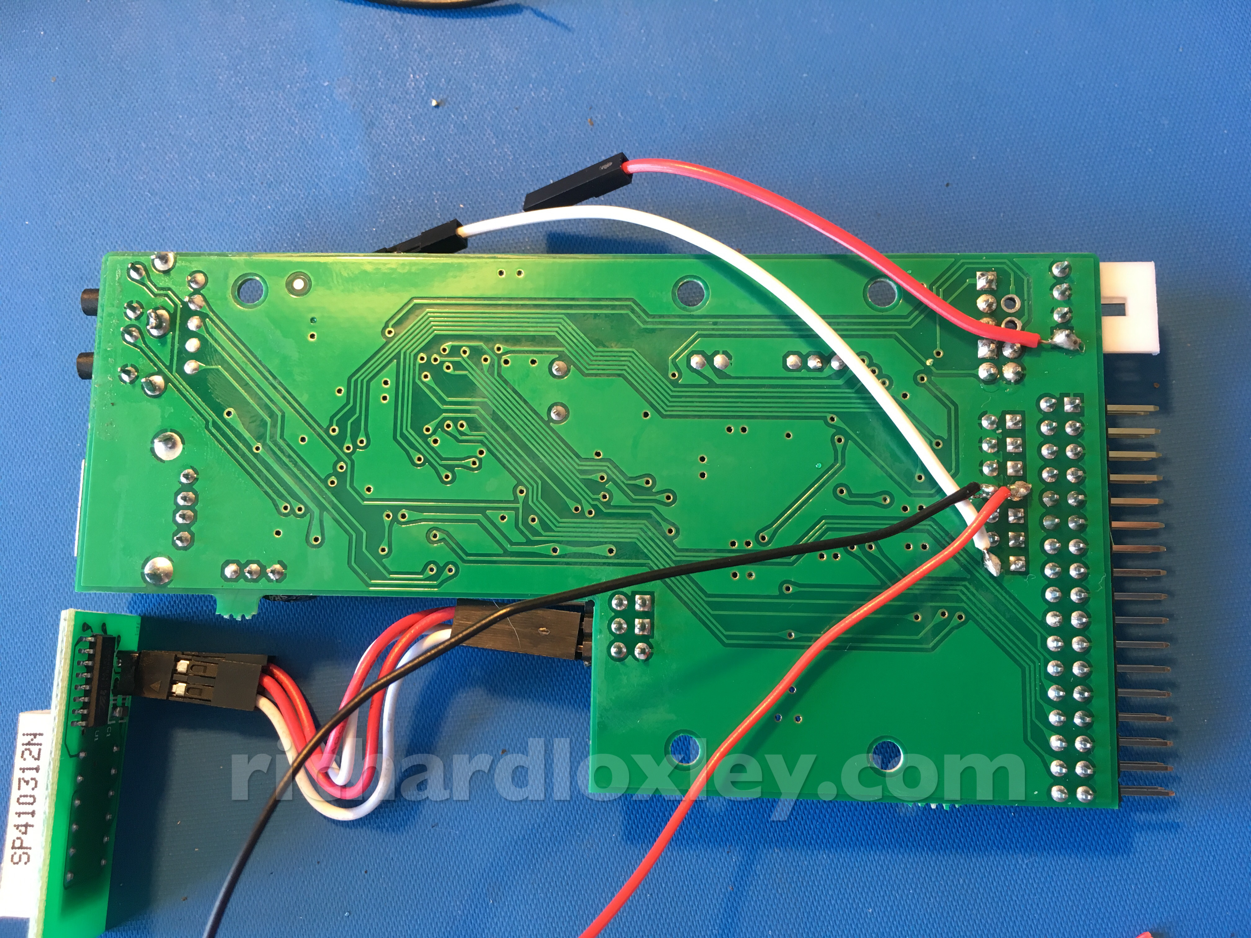
I made connections for 5V, ground, drive select, and also two extra wires for a piezo sounder (for sound effects).
All done:
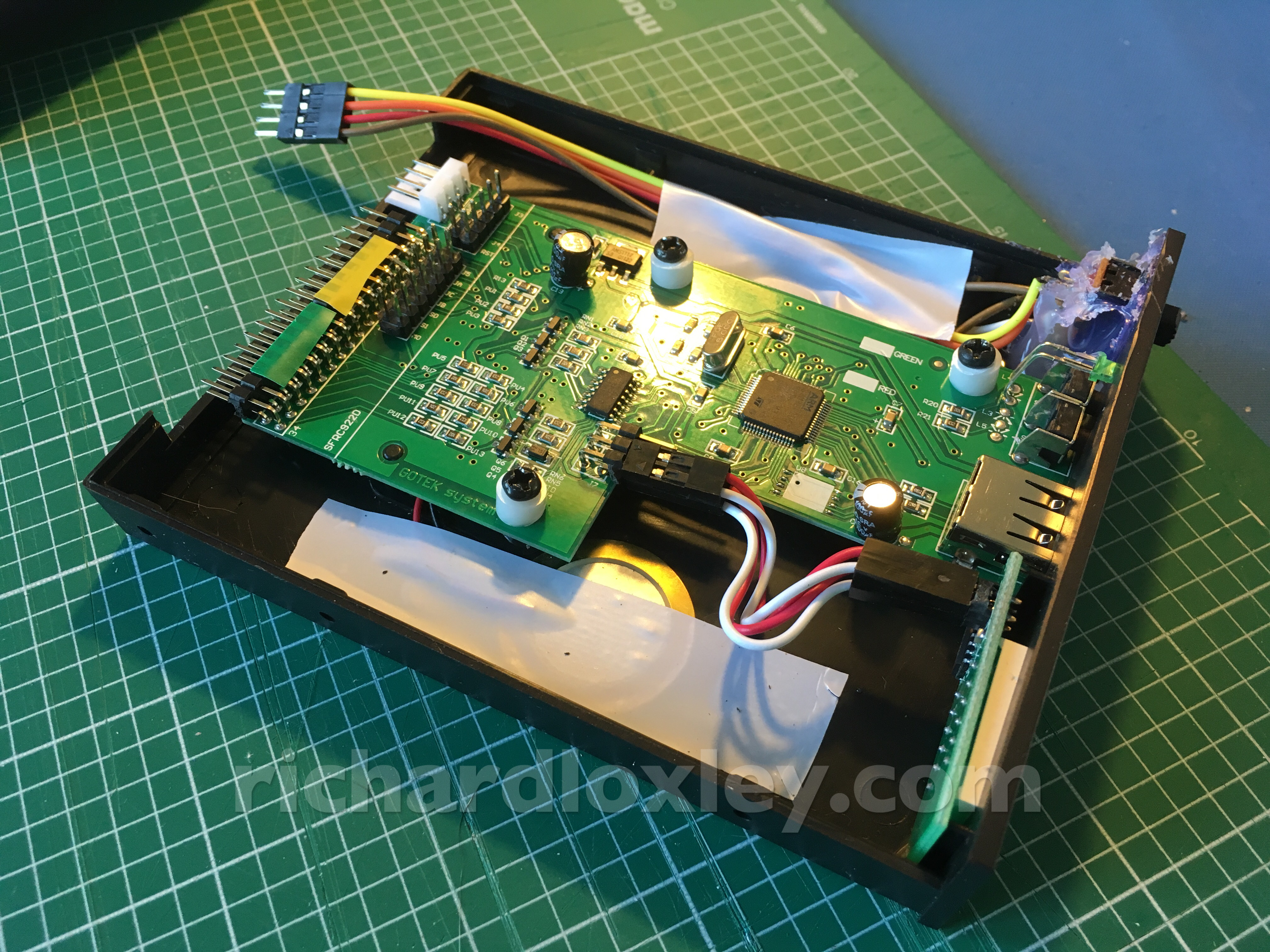
Now to test it:
Sadly, it didn’t work quite as expected. The switch to turn off the Gotek didn’t work! When turning it off, the display dimmed, but it still ran.
Of course, the signal lines connected at the back from the Osborne were being pulled-up to 5V at the Osborne end. The circuit board was being powered from those lines!
So I re-soldered it, and instead of switching the 5V line, I switched the ground. That did seem to correctly switch off the Gotek. But then the internal drive wouldn’t work reliably. I’m guessing that because the ground was disconnected but the two circuits were still connected at a 5V reference point, the signal lines at the Gotek end were interfering with the other drive :-(
So I needed to switch both ground and 5V to reliably disconnect the Gotek drive.
So really I needed a 3PDT switch instead of a DPDT one.
But a quick look showed there weren’t any readily available in a small enough form factor for my purposes.
Other options I considered were:
- Have two switches: one to turn the Gotek on and off, and the other to switch between the drives. Not very elegant though.
- Leave the Gotek permanently powered when the Osborne was on, and just switch the drive select lines. But I liked the visual clue of which drive was selected, and I preferred the Gotek to not be ‘lit up’ when using the machine in unmodified mode.
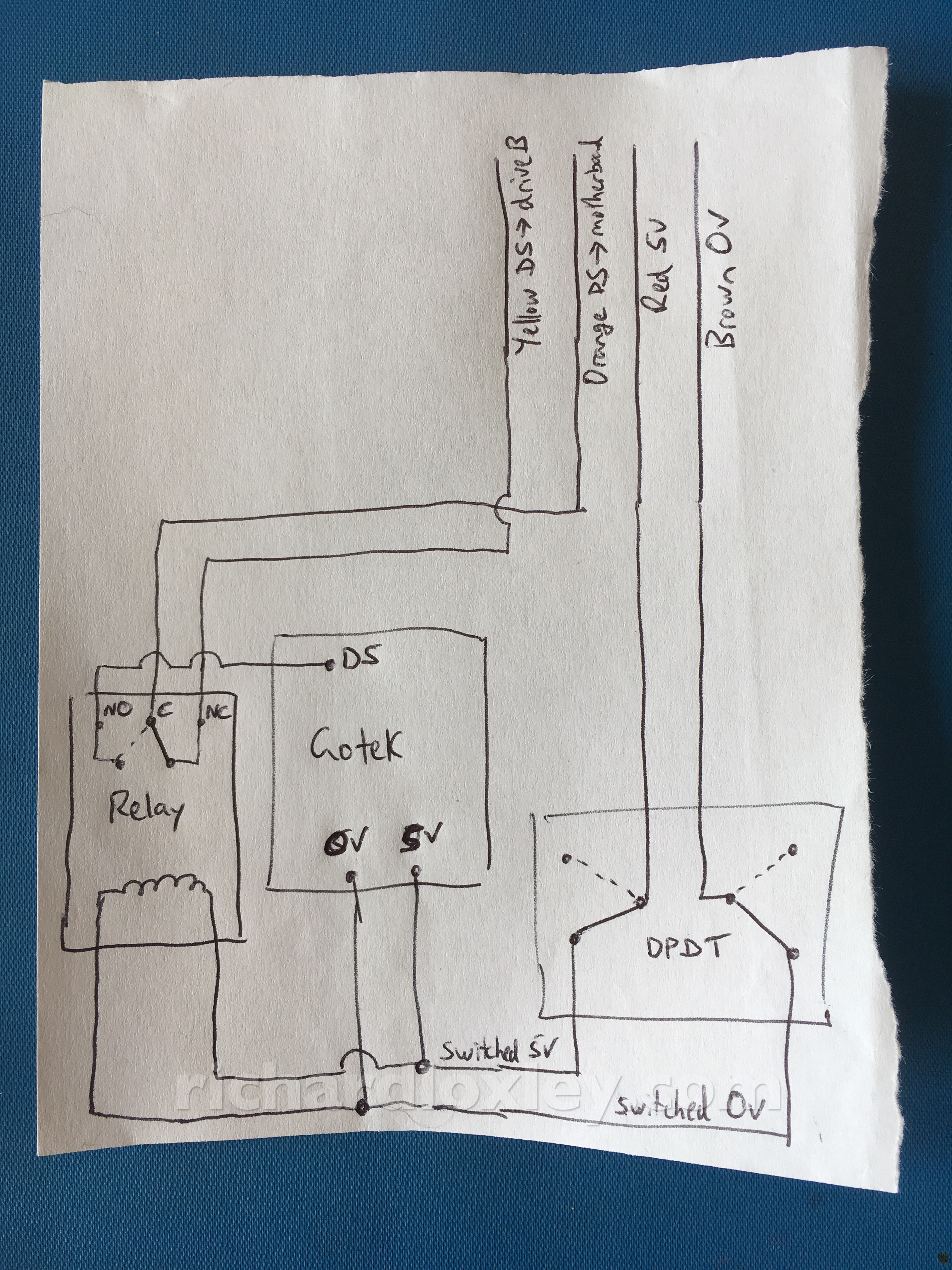
Finally I came up with a better solution. I would use the DPDT switch to switch both ground and 5V, then add a relay (powered from the switched 5V supply) to switch the drive select line.
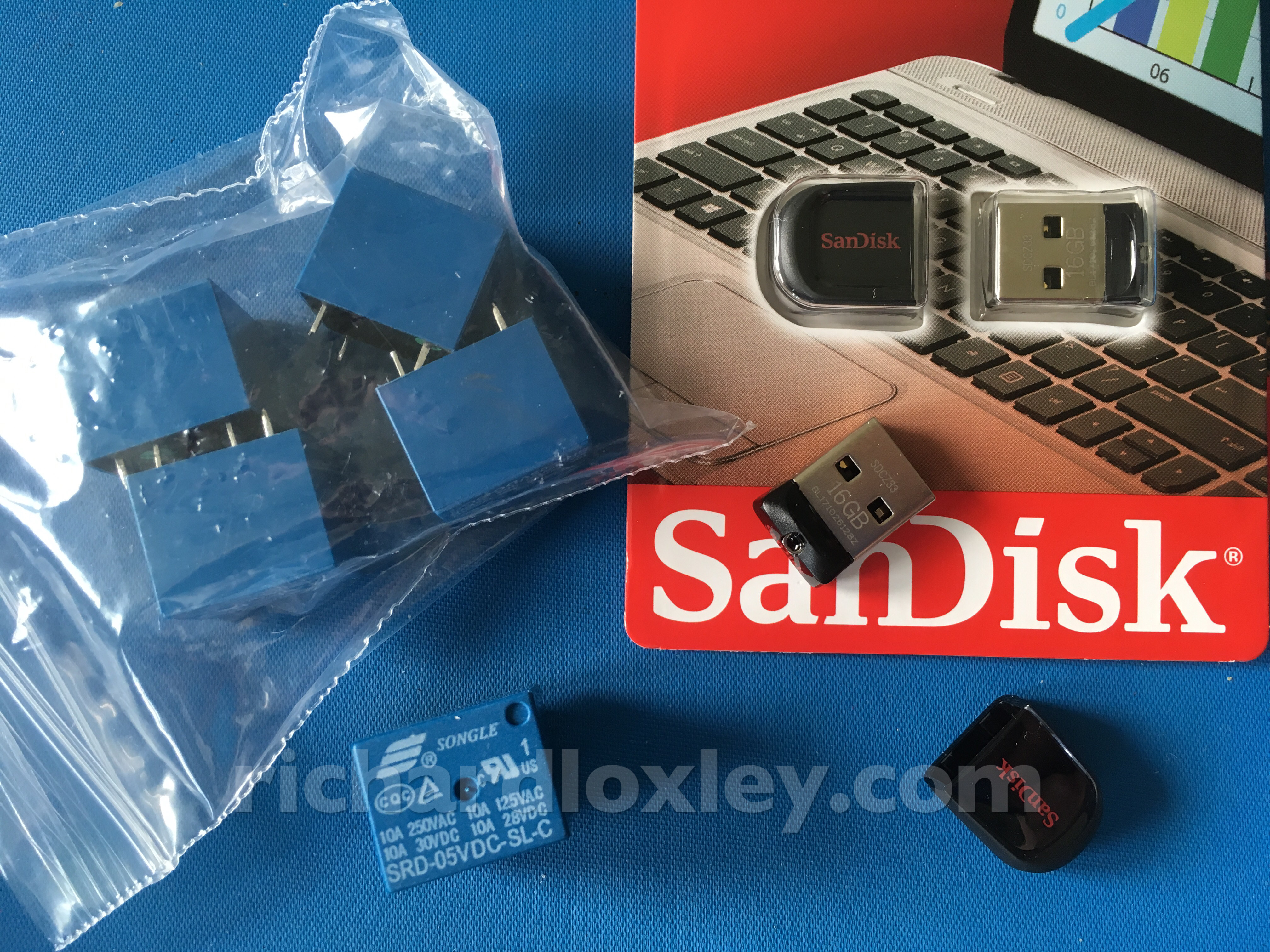
The only problem was all my relays were 12V (unless I unsoldered one from another board). So time to hit eBay again!
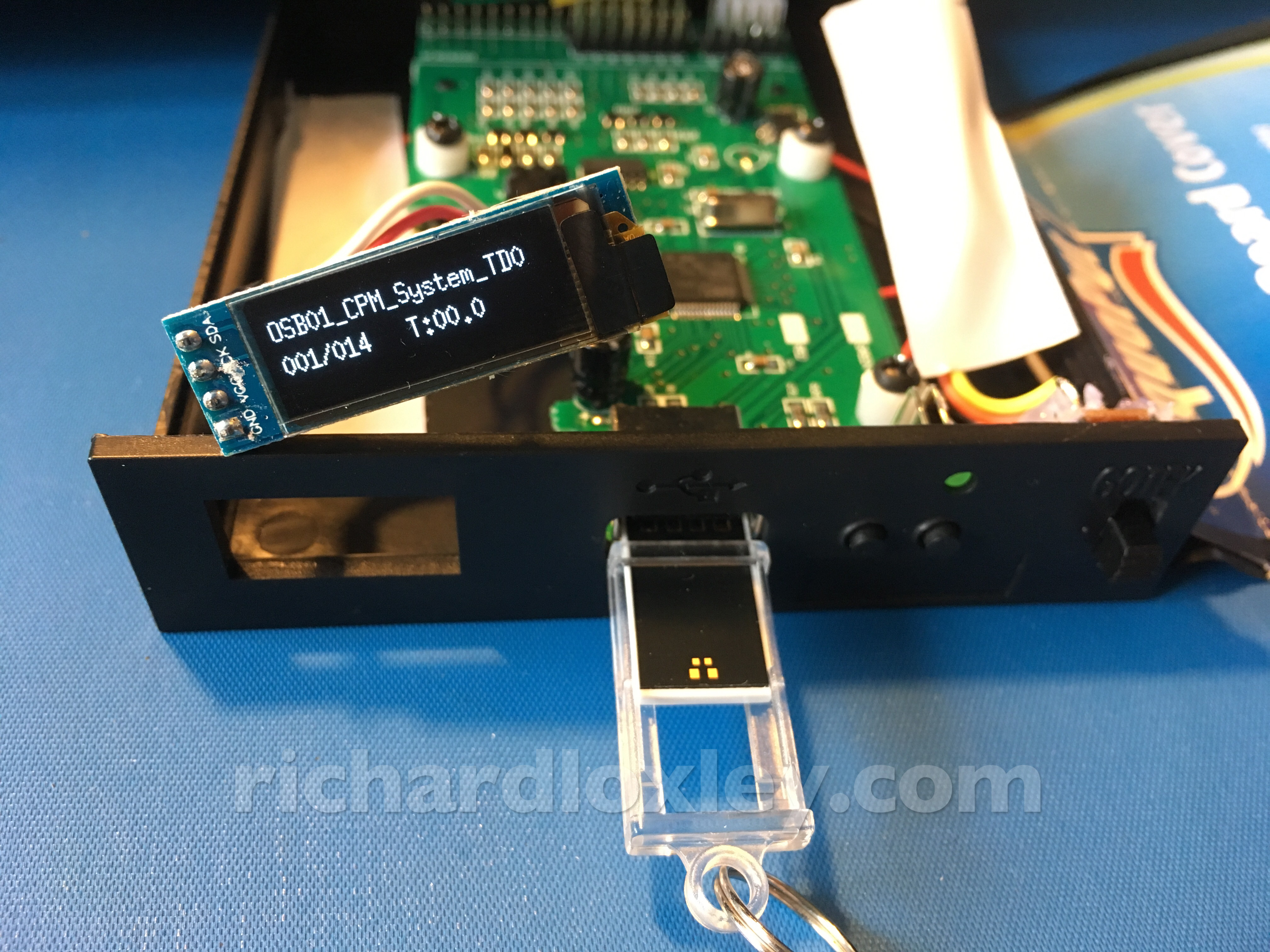
While waiting for the relays to arrive, I had another surprise in the post. The OLED displays I had ordered from China had turned up :-)
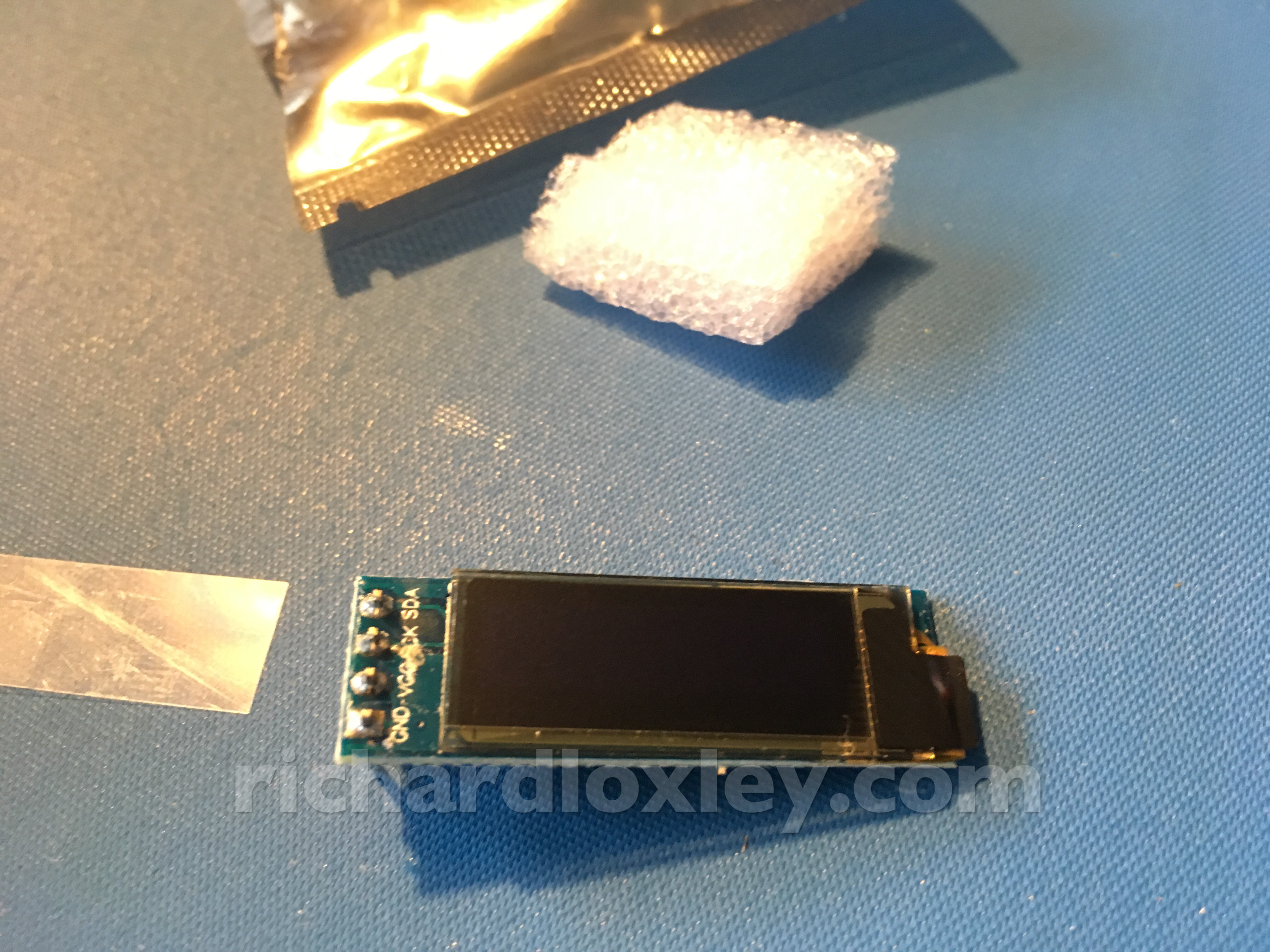
Testing it out:
It’s wider than the LED display it replaces, so these plastic mounts need cutting away:
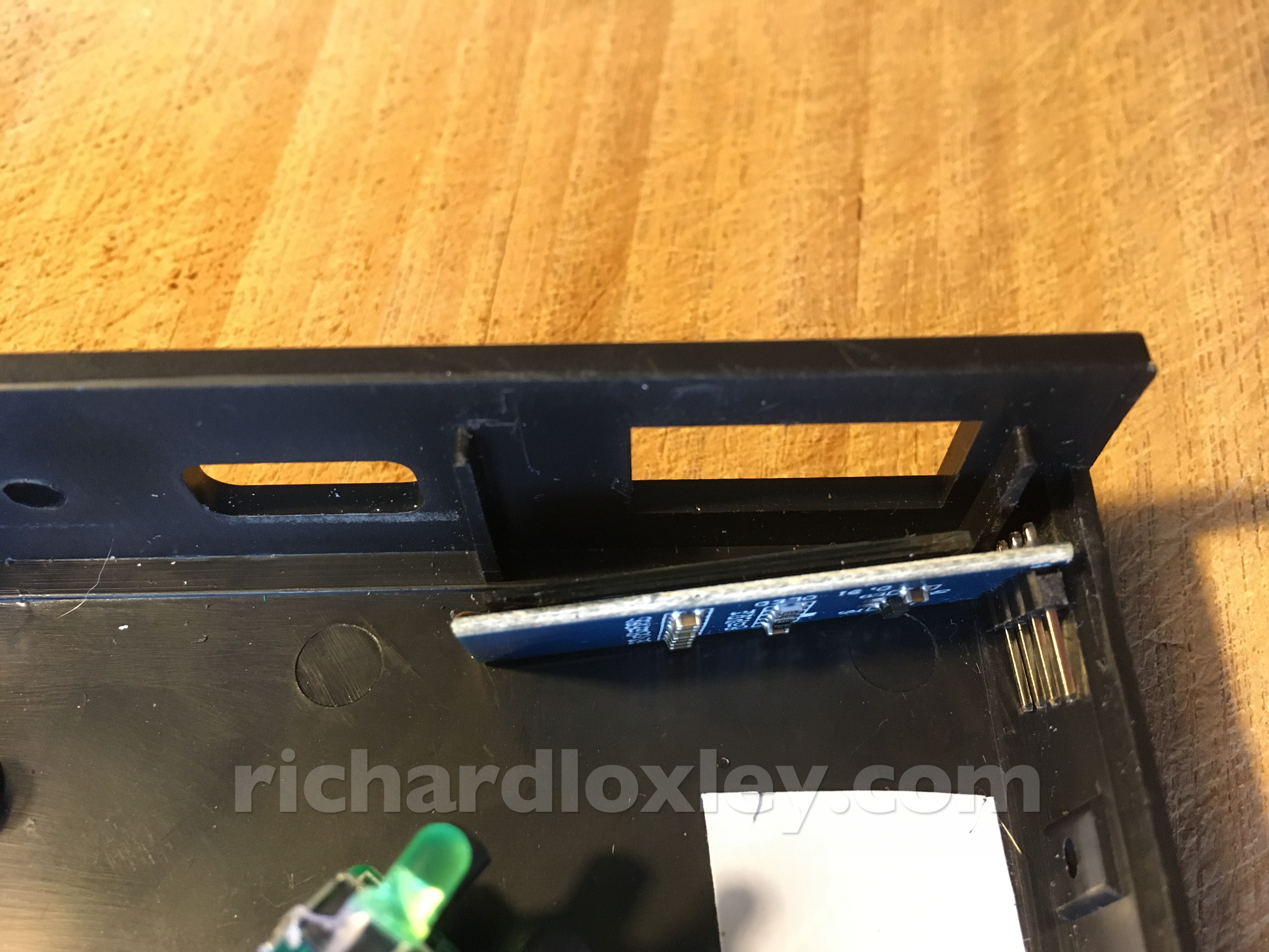
I also needed to cut a small groove to the right so the display was correctly aligned with the hole:
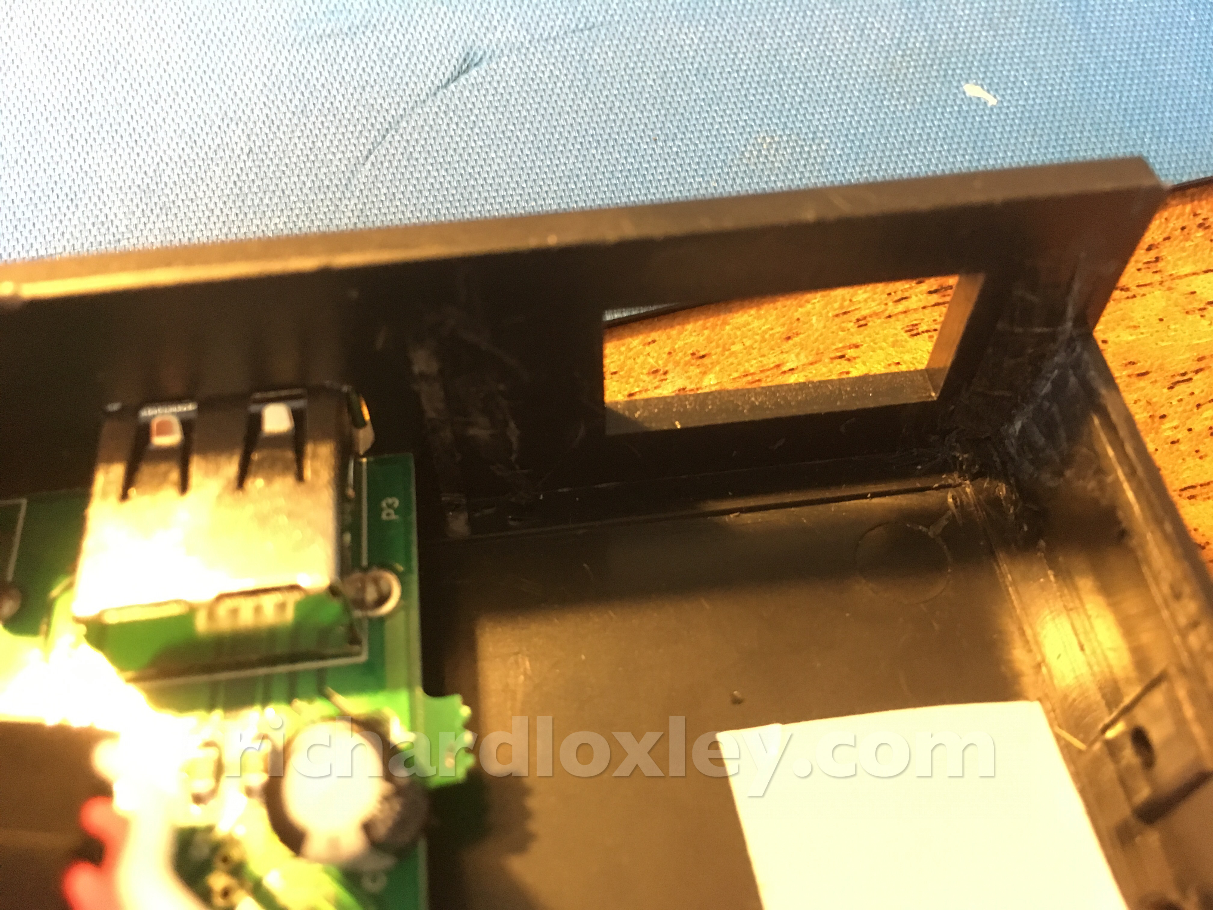
And more hot-glue to fix it in place:
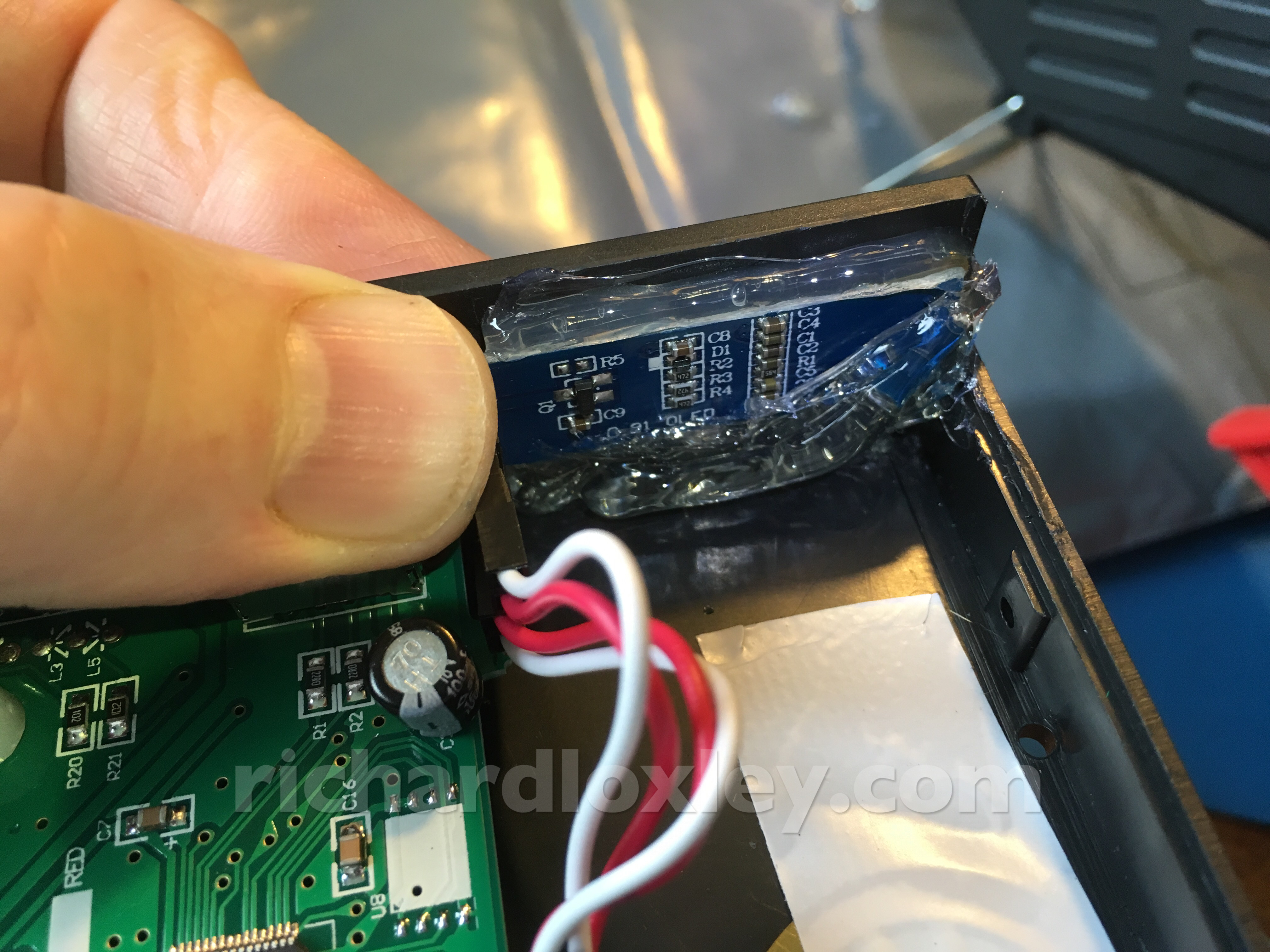
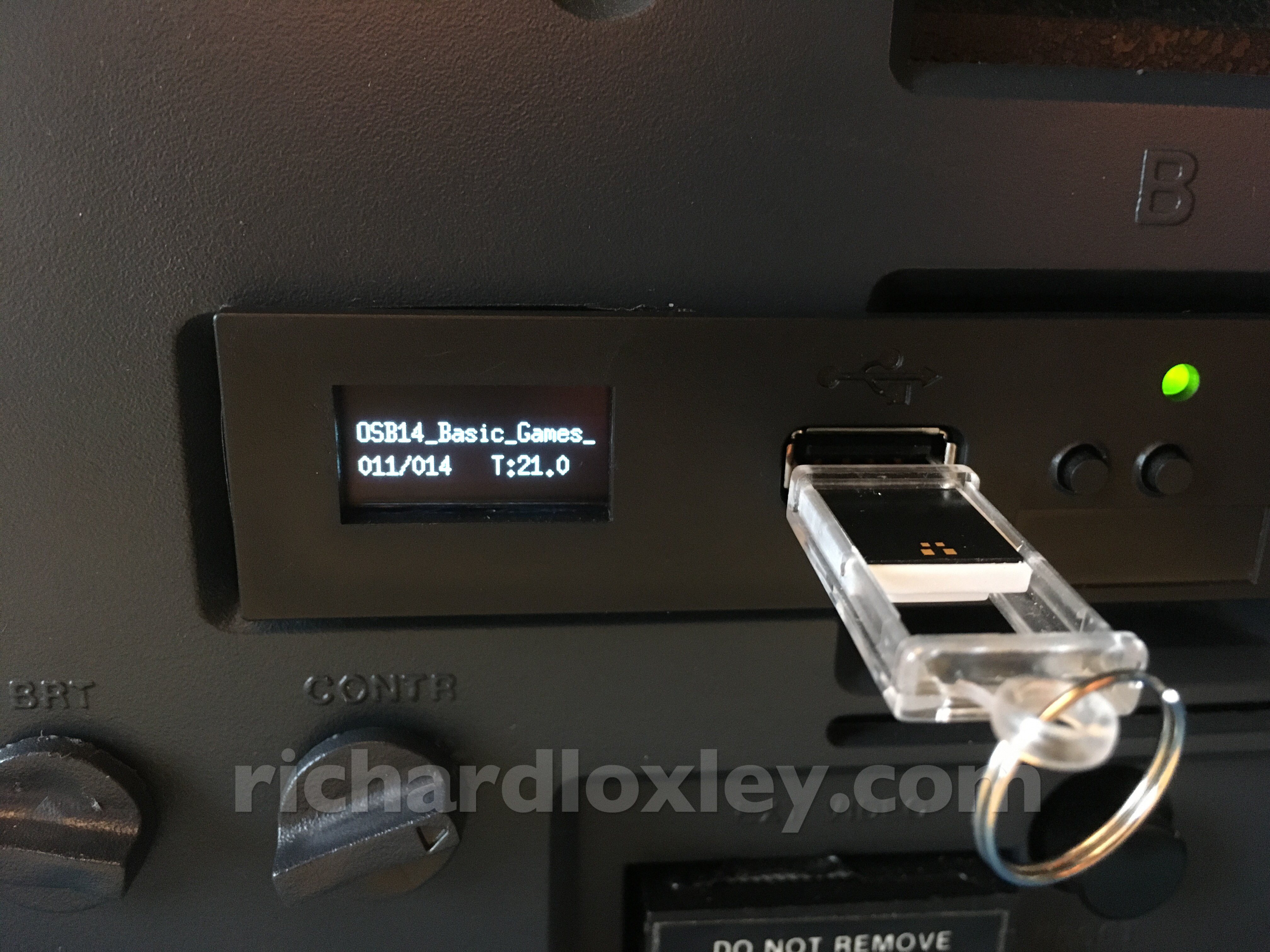
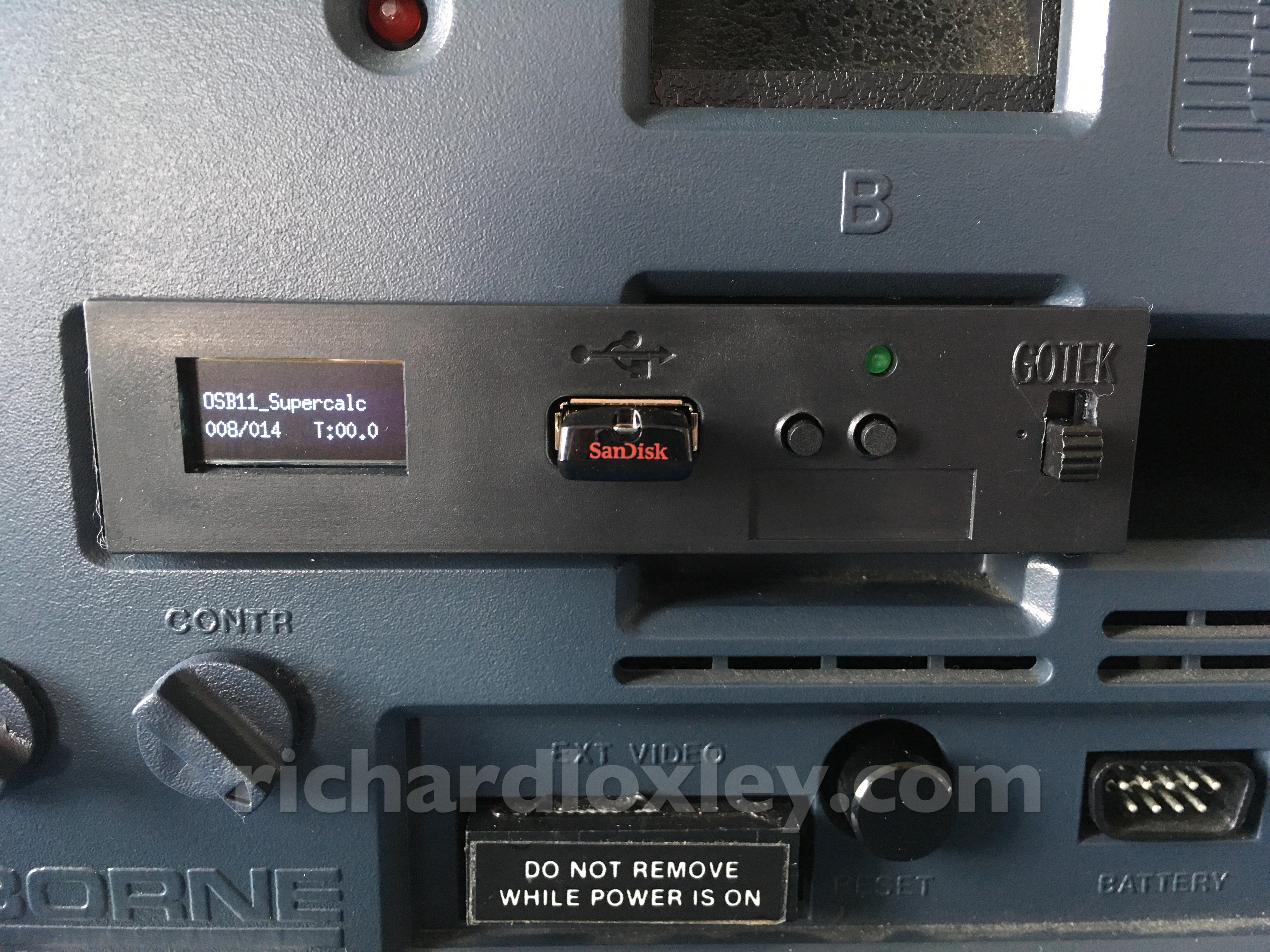
Looking good! The display is wider than the cut-out, but the FlashFloppy firmware allows you to select a smaller display area so you can use the existing cut-out. It only reduces the display from 21 characters to 18, so I thought this was better than a home-made looking hole.
More deliveries. Not only the 5V relays, but also some tiny USB drives :-) I’m hoping they are small enough I can leave one in the drive when the Osborne keyboard is closed.
This is the revised circuit diagram for the switches:
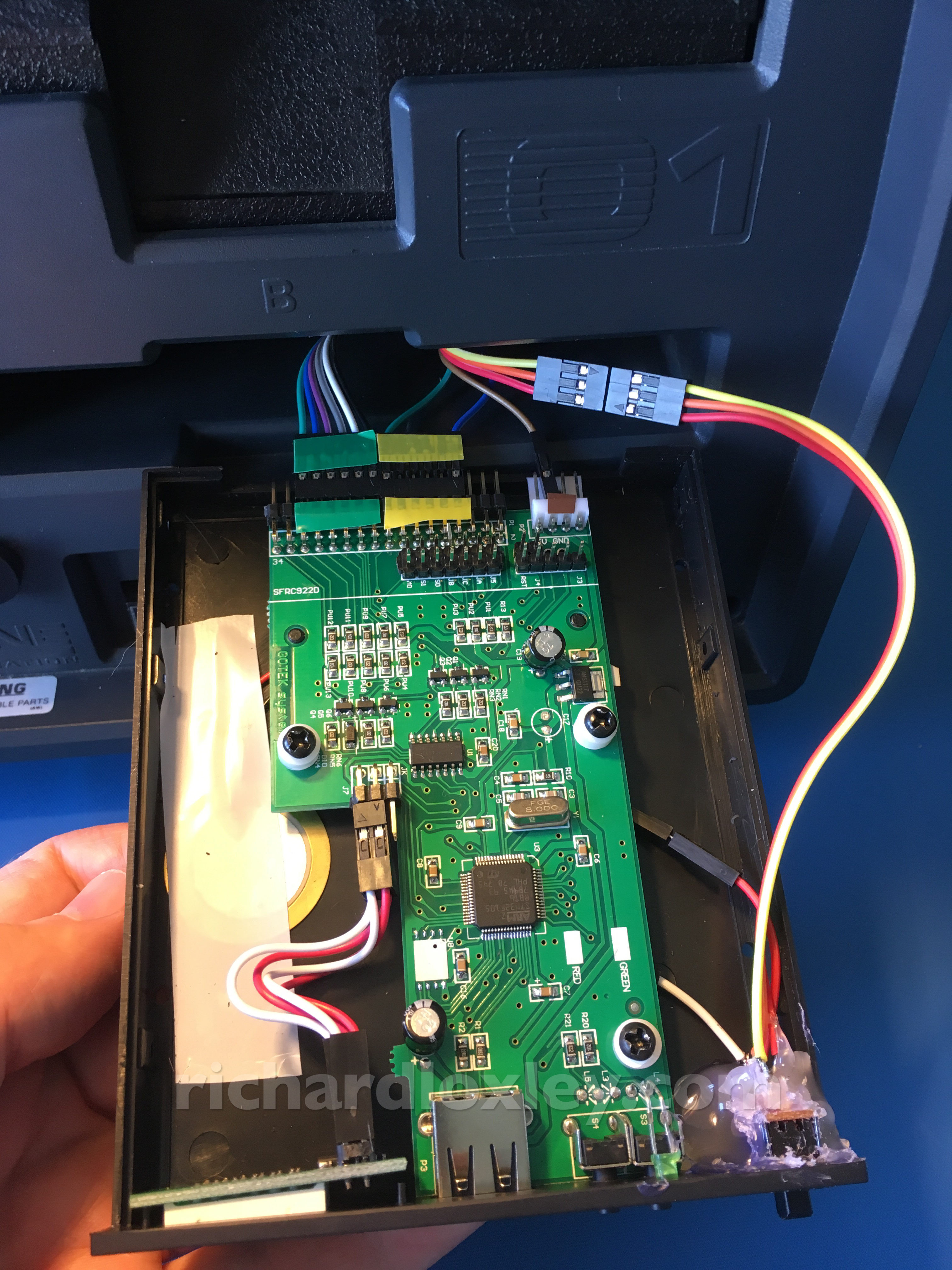
Soldering up the relay and switch:
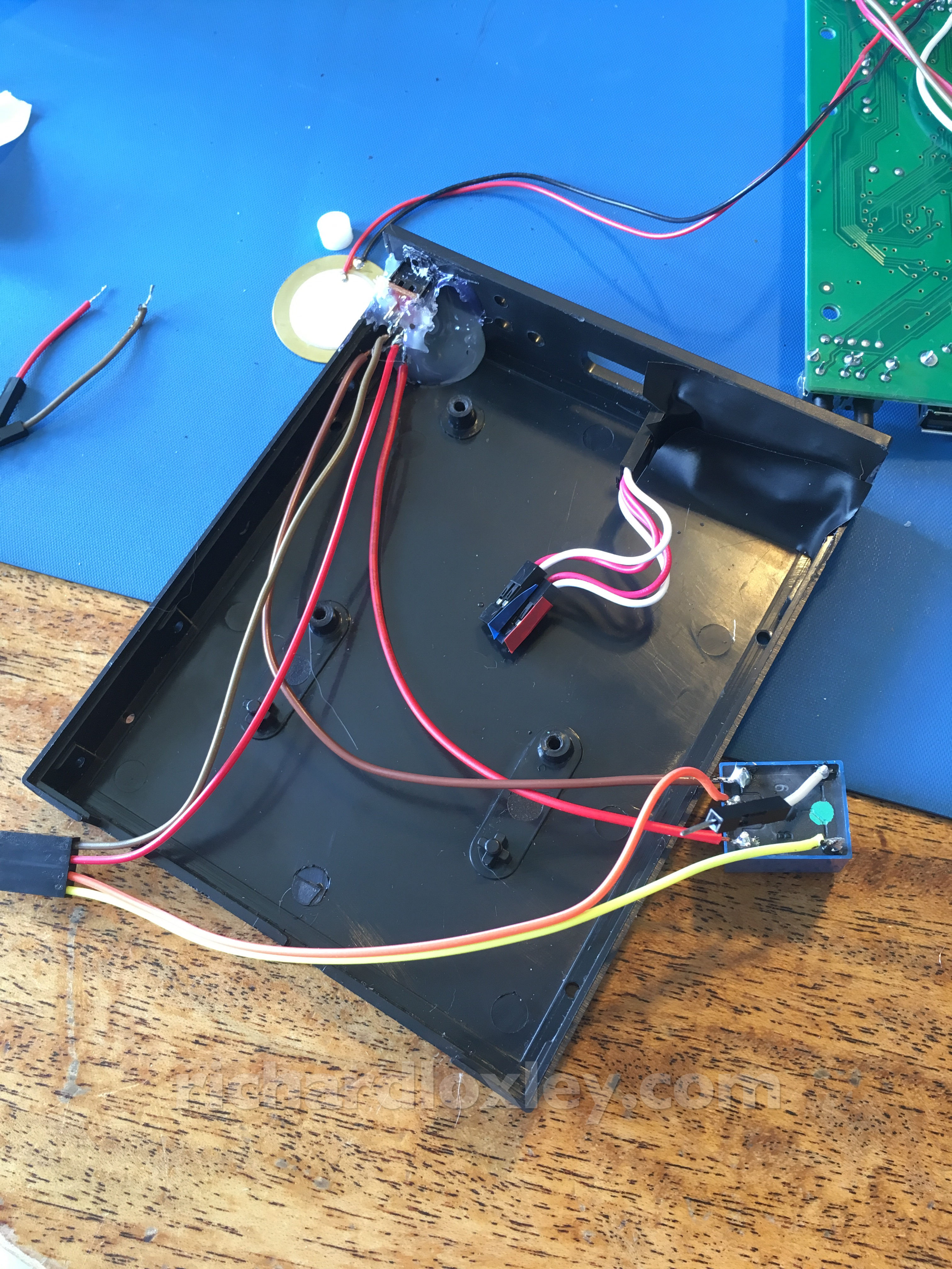
All done:
Time to make a top-cover for the drive (since the plastic top won’t fit in the slot where it’s going). First a bit of cardboard modelling:
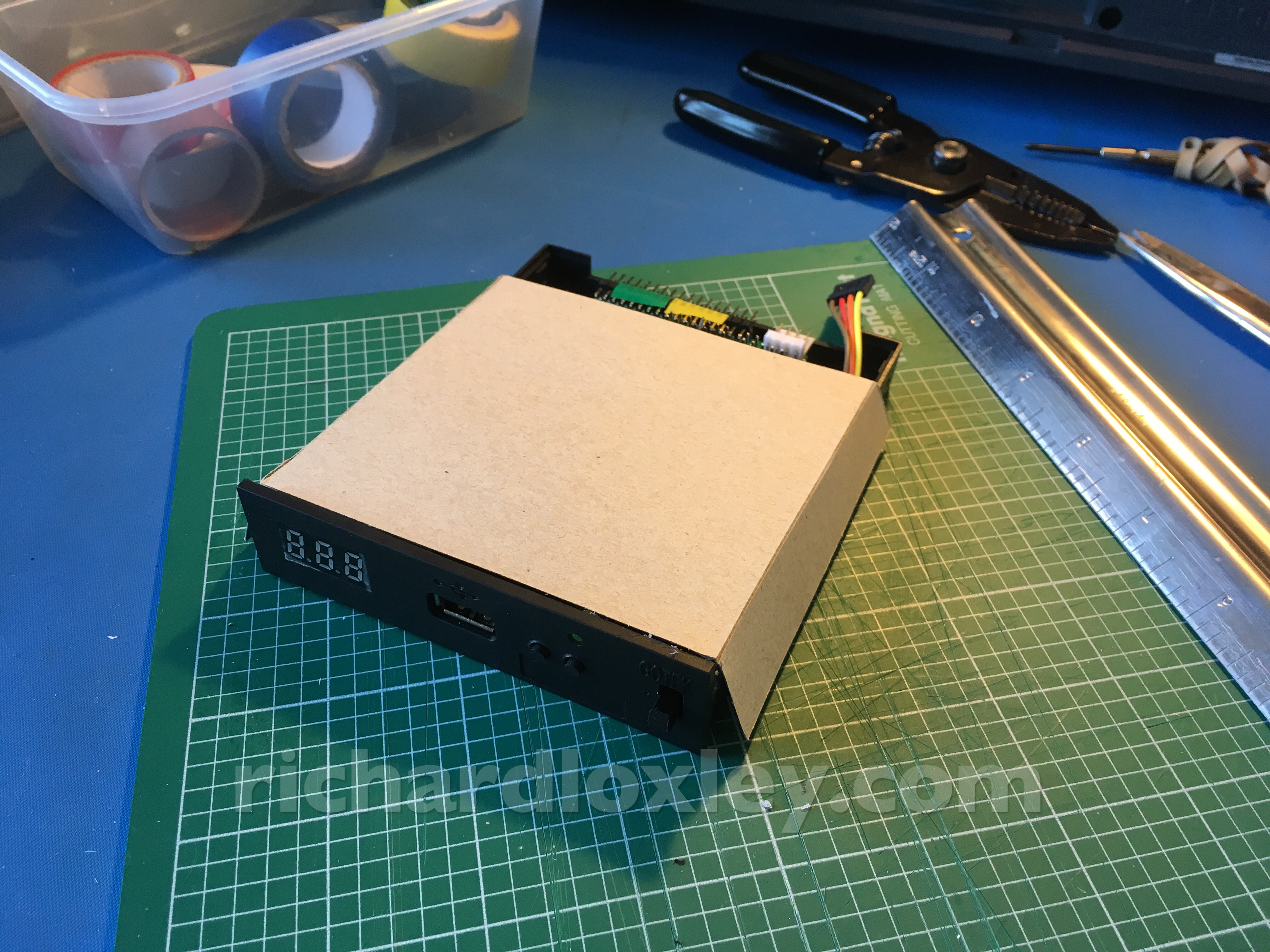
Then black electrical tape for a more refined look:
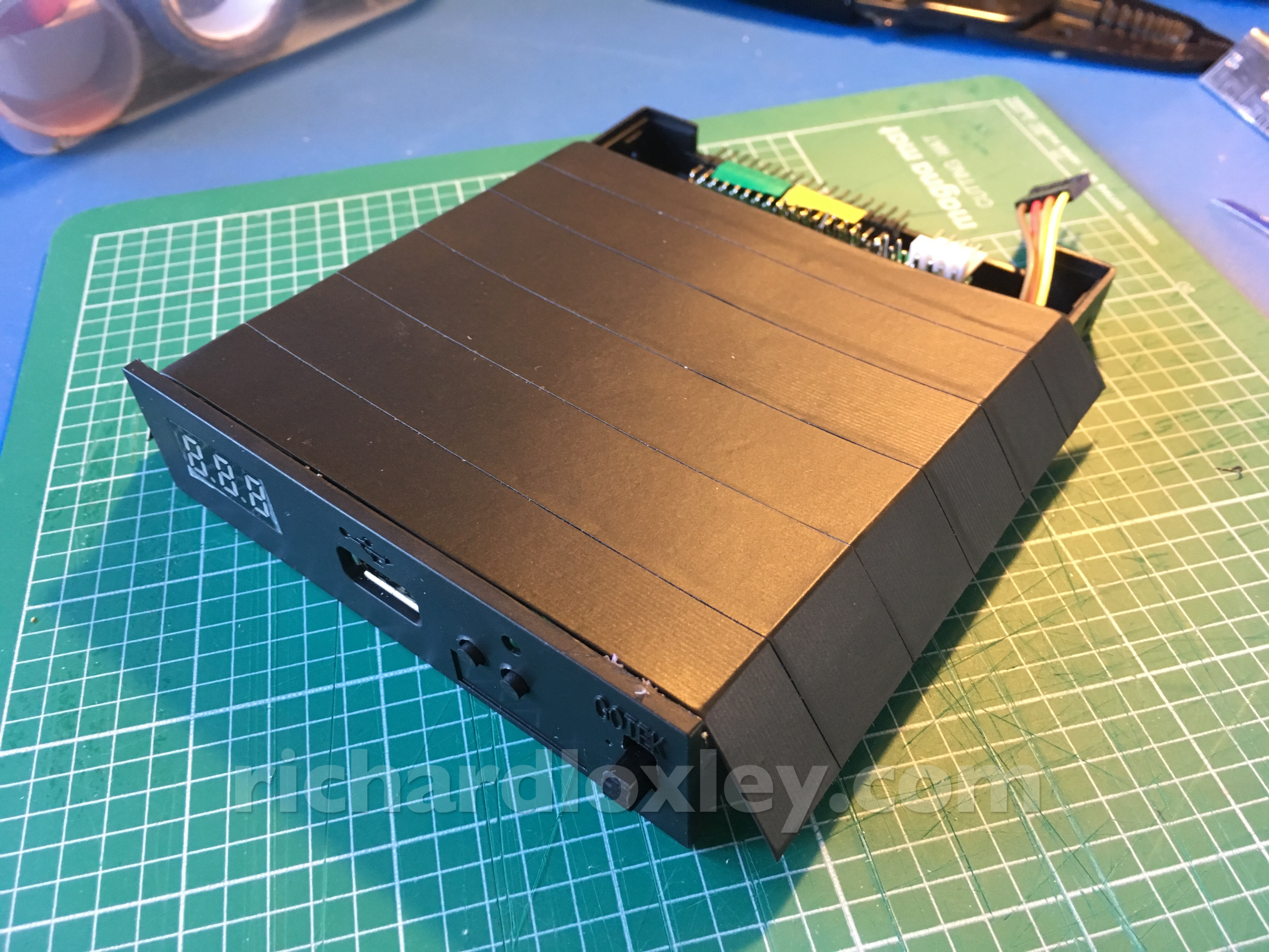
Looking sweet!
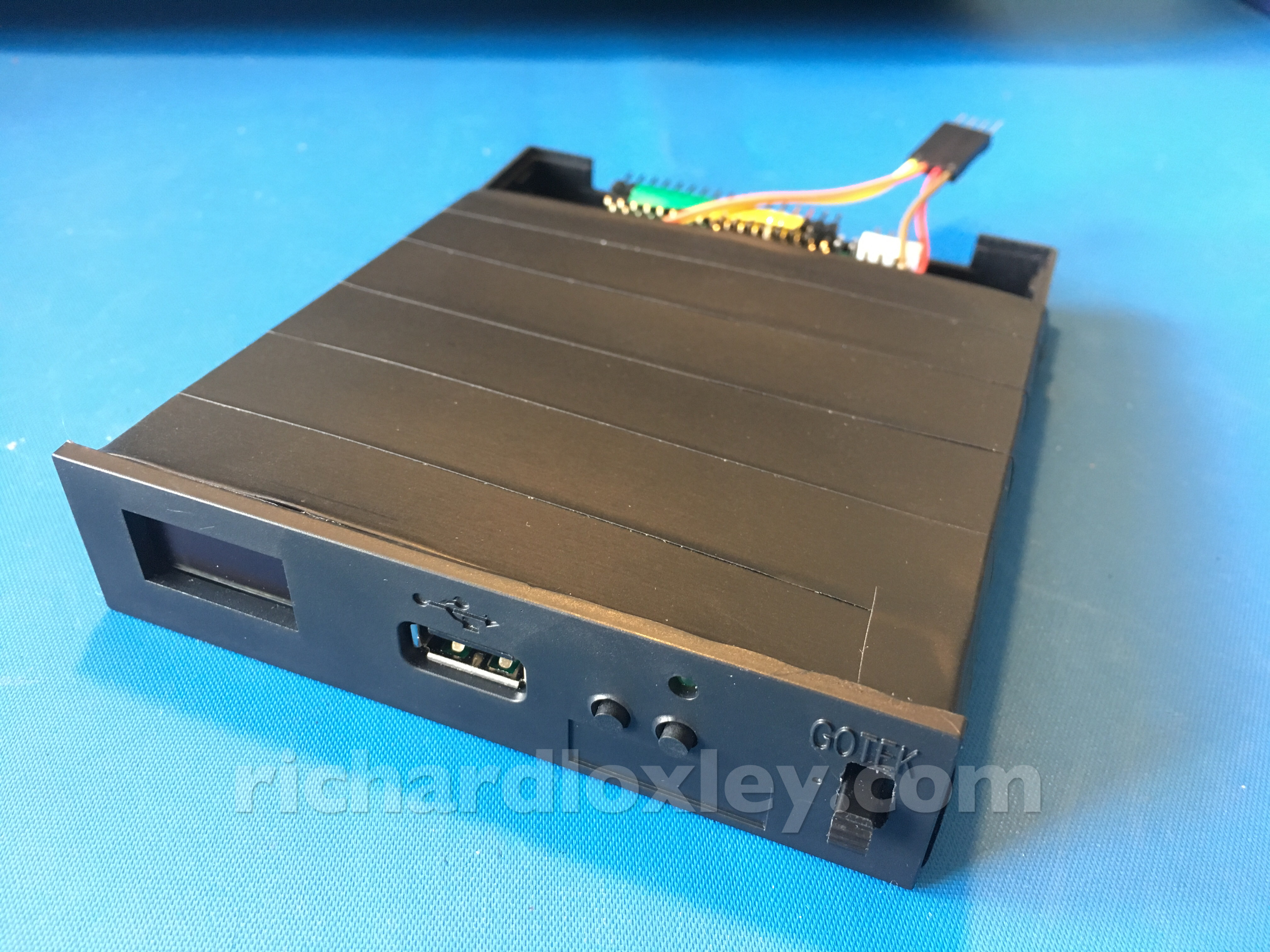
Connecting it up (colour-coded as always – although that hasn’t always stopped me putting them in upside down):
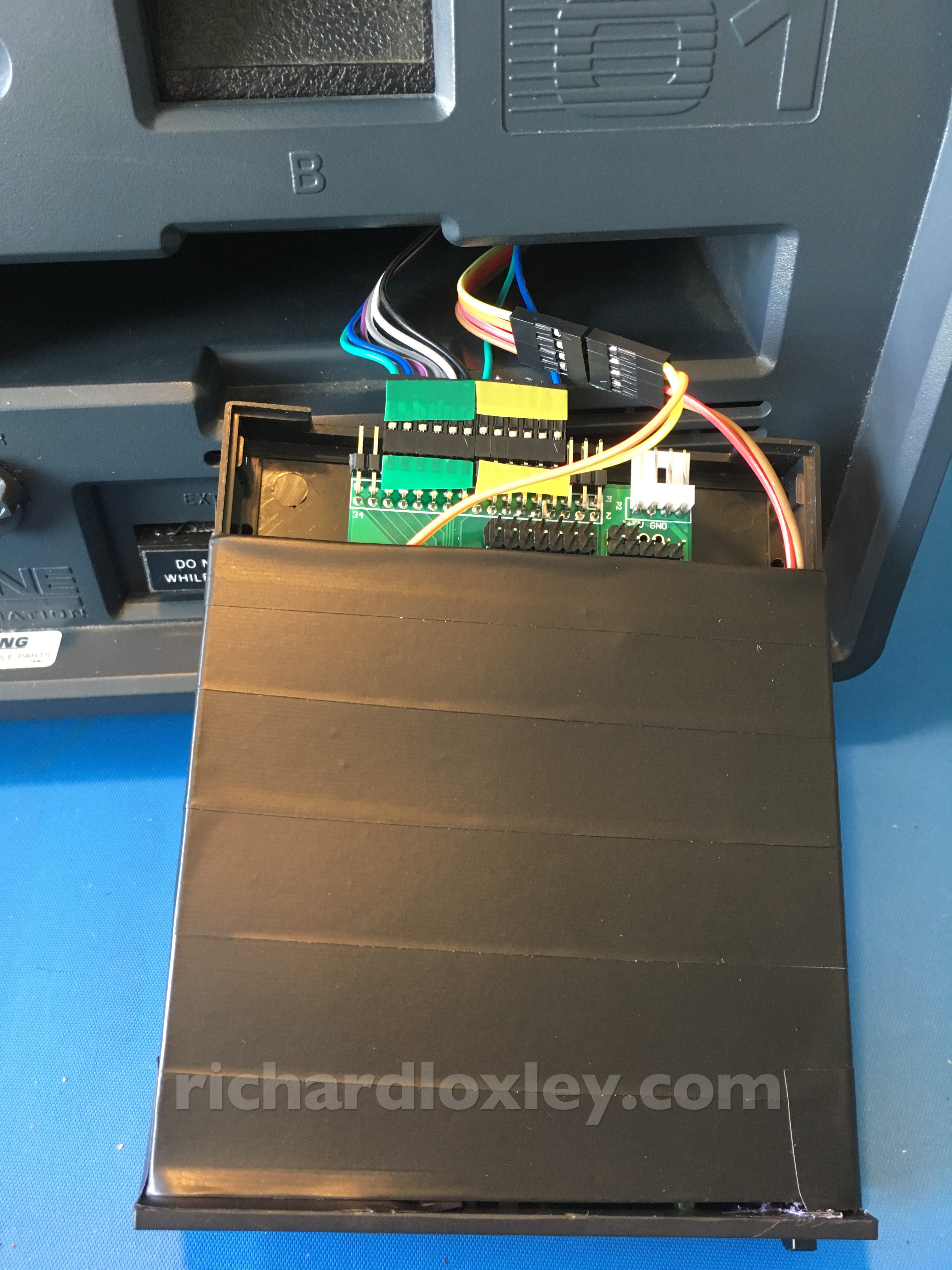
All in place, and working fairly well. The cardboard case makes it a snug fit, so it stays in the slot just by friction.
The only issue I’ve found is after using the internal drive, when switching back to the Gotek the display doesn’t always come on. I notice the FlashFloppy firmware has some settings for display detection (it tries to auto-detect the display type). I might need to play around with those settings.
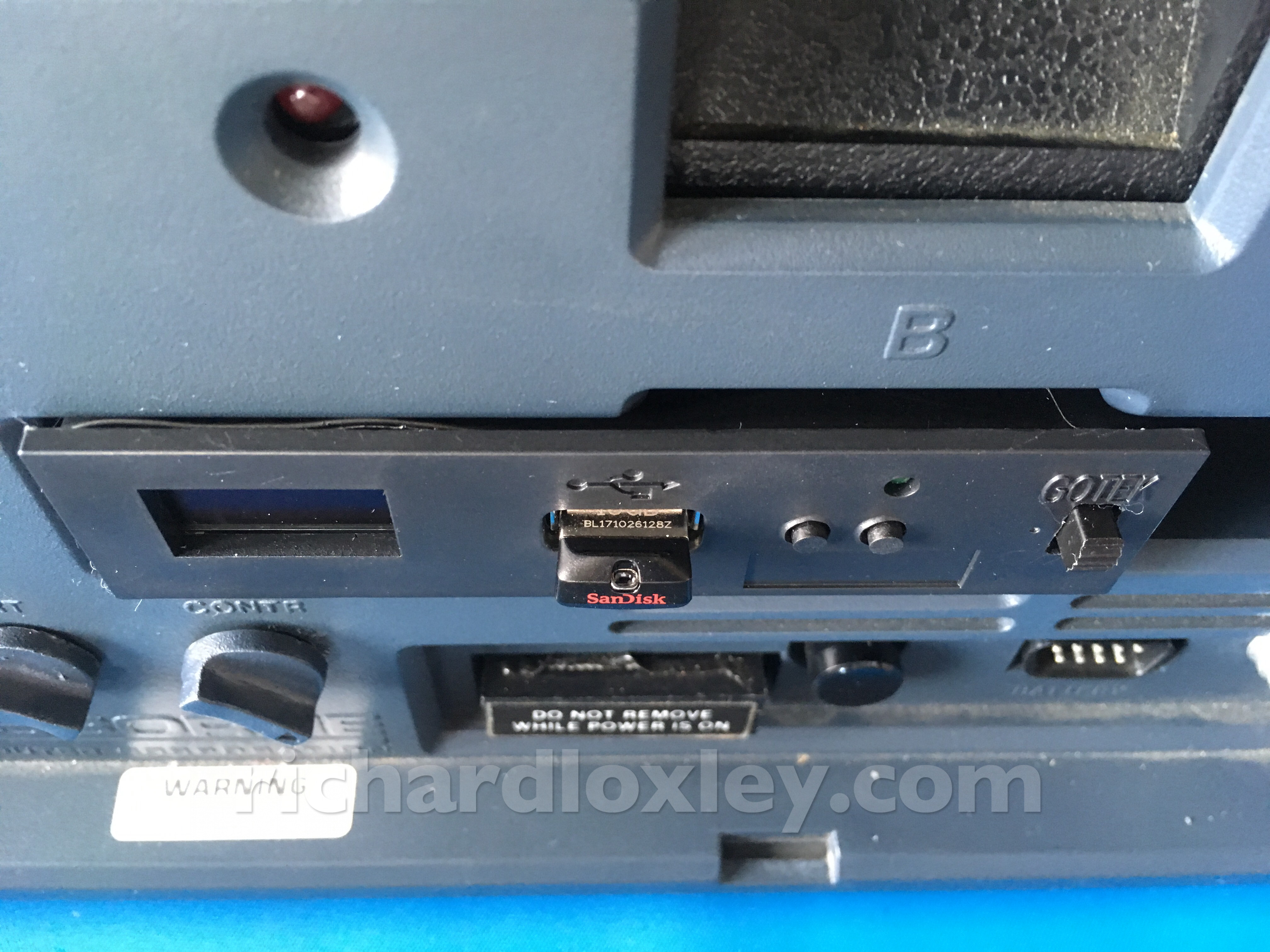
That tiny USB drive is very sweet:
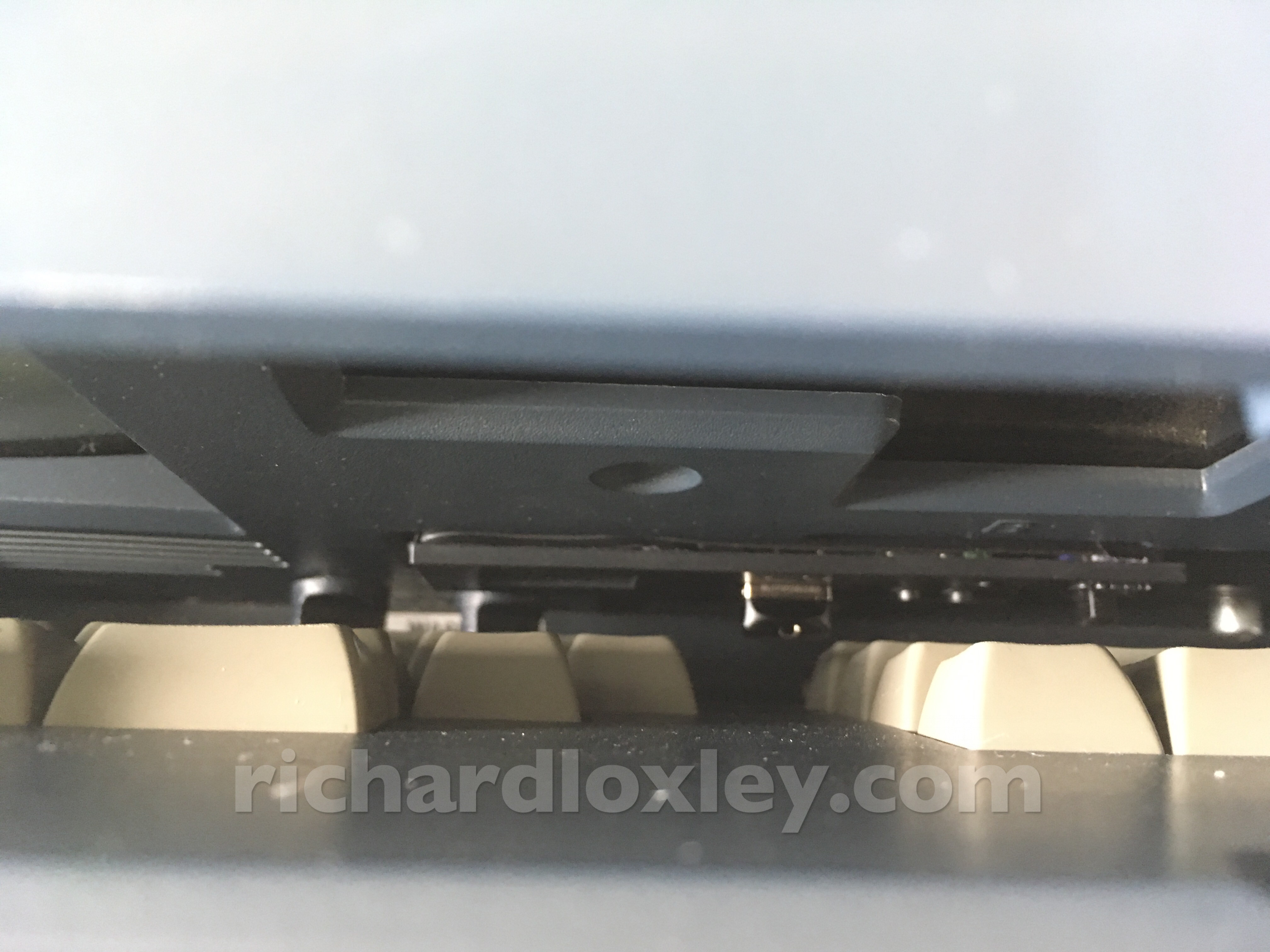
And it fits even with the keyboard closed :-)
Finally here’s a quick demo of the drives in action:
Love that the keyboard has a nice key-gap to fit the mini USB stick…